Khmelnik force

Author: Solomon I. Khmelnik
Journal: Доклады независимых авторов @dna-izdatelstwo
Section: Physics and astronomy
Article in issue: 28, 2014.
Free access
It is shown that from the existence of electromagnetic momentum flow and from the law of momentum conservation there follows the existence of a previously unknown force. The author suggests to experimenters to verify the generation of Khmelnik force and to supplement its name by their own names
Short address: https://sciup.org/148311846
IDR: 148311846
Text of the scientific article Khmelnik force
In [1] it is shown that the Lorentz and Ampere forces can be defined as the consequences of the existence of electromagnetic momentum flow and of the law of momentum preservation. They are defined in the form (in SI system):
F = V • S • ^г:шc , (1)
where
S - the energy flow density,
-
V - volume of body, which is penetrated by the flow of electromagnetic field,
-
ε - relative permittivity of body,
-
µ - relative permeability of body,
-
c - light speed in vacuum.
-
2. Faraday motor
Based on this form it can be asserted that there exists an additional force which we shall call for short “Khmelnik force” (if, of course, nobody had considered previously this force). In particular, it can be the Lorentz force or the Ampere force. But in other cases it is not equivalent to these forces. Consider some of these cases.
The most striking example of such a force can be observed in the design shown in the following Fig. 1. "The inventor of this motor took disc of neodymium magnet with nickel coating, magnetized along the axis, in the center attracted to it by magnet a screw with a sharp end, and that end attracted by magnet to the positive terminal of round battery. Then he connected the negative terminal of the battery by thin wire (like a brush) with cylindrical surface of the magnet. Thus, between the tip of the screw and the positive terminal a bearing with very low friction was formed. When the negative terminal of the battery was connected to the magnet circle, the magnet spun immediately and within a couple of seconds has reached a top speed of the order of 15,000 rev / min, and then due to imbalance broke from the screw and flew away!” The quote and Fig. 1 are taken from [2], but one can easily replicate this experiment. Earlier in [2] a brief explanation of the experiment was given.
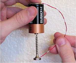
Fig. 1.
In essence, it is - a special case of Faraday motor - see Fig. 2. It has a electroconductive magnet with induction B , the line of current I passing along the vertical axis (vertical screws on Fig. 1), along the magnet's radius and the fixed contact. On electroconductive radius has electric intensity
E = j ρ , (2)
where j - the current density, ρ - resistivity. Magnetic intensity H is proportional to the induction B . Vectors of these intensities are mutually perpendicular and therefore there flows of electromagnetic energy
S = EH (3)
arises. It is shown in Fig. 2 as two circles in the plane of the magnet. Note that this flow occurs in a static electromagnetic field. This flow creates a force F that rotates the magnet at a speed v . This force is
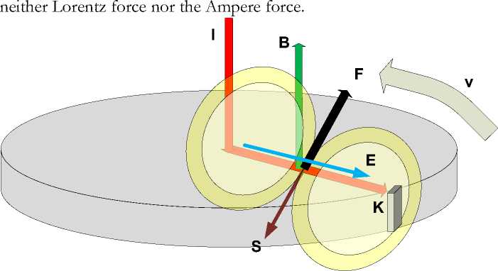
Fig. 2.
In [4] Tamm describes the following mental experiment – see Fig. 3. He considers a cylindrical capacitor placed in a uniform magnetic field Н, parallel to its axis. In the space between the capacitor plates, in addition to the magnetic field, there is also a radial electric field of intensity E, created by the charged capacitor. In the space between the capacitor plates in the static electromagnetic field there exists the Pointing vector (3). The lines of Pointing vector, i.e. the energy flow lines, are concentric circles whose planes are perpendicular to the axis of the capacitor.
Experimental setup is shown on Fig. 4, where
-
1 – cylindrical capacitor,
-
2 – torsion oscillator suspension,
-
3 - mirror,
-
4 - radially extending wires for supplying an alternating voltage to the plates,
-
5 – superconducting solenoid.
-
5. Ivanov’s Mental Experiment
The authors write: "Our programme of measurement of forces related to electromagnetic momentum at low frecuencies in matter has culminated in the first direct observation of free electromagnetic angular momentum created by quaststatic and independent electromagnetic fields E and B in the vacuum gap of a cylindrical capacitor. A resonant suspension is used to detect its motion. The observer changes in angular momentum agree with the classical theory within the error of ~20%. This implies that the vacuum is the seat of something in motion vhenever static fields are set up with non-vanishing Poynting vector, as Maxwell and Poyntin foresaw."
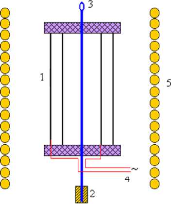
Fig. 4.
The experiments of Tamm, Graham and Lahose are discussed by Ivanov in [6] (from this work the illustrations are taken). From these, by his opinion, follows that “angular momentum of matter and field is not stored”. Later, in [7] he presents a construction shown on Fig. 5. He assumes that his construction will be moving only with alternate voltage. His proof is based on the “laws of momentum and energy conservation and relativity principle, according to the named laws such movement takes place due to the force and energy interaction with physical vacuum (ether)”.
On Fig. 5 shows
-
1. inner electrode,
-
2. outer electrode,
-
3. reel from magnetic dielectric material,
-
4. coil magnetization reversal,
-
5. electrical circuitry.
-
6. The proposed device
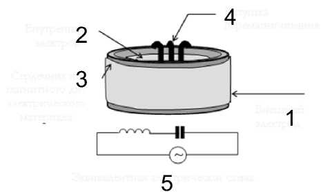
Fig. 6.
All the above named experiments cannot be explained by the Lorentz forces or Ampere forces, but can be easily explained by the forces (1). Most clearly this can be shown on the further proposed device.
Let us consider Fig. 7, that shows a body located inside the solenoid with direct current I . The body has covering electrodes under direct voltage U . In this case, the body creates electromagnetic stationary field with electric field intensity E and magnetic field intensity
H . In the body appears a flow of electromagnetic energy with density (3), which is shown in the Fig. 3 by circles. It can be presented in the form of two spheres united in a body and threading it in the vertical direction. This flow creates force (1) acting on the body.
F
E
A h
__I
+U
H
S
d
L
Fig. 7.
Let us discuss in detail the calculation of force (1), using the notations of the body dimensions shown in the Fig. 7 ure: L,d,h . We have:
E = U I d ,(4)
H = Iw IL ,(5)
V = hdL.(6)
Also
F = V • E • H • ^Sju]c ,(7)
or
F = hUIw4^(c.(8)
The example. Let in SI system ц = 1, e = 4, c = 3 • 108, и = 30000, I = 20, h = 0.2, w = 100.
Then F = 0.2 • 30000 • 20 • 100V4T/3 • 108 = 0.08 [7 V ] .
Thus, we may expect that the device can be implemented . The author suggests to experimenters to verify the generation of Khmelnik force and to supplement its name by their own names.
