LabVIEW based Condition Monitoring of Induction Machines

Author: K.Vinoth Kumar, S.Suresh Kumar
Journal: International Journal of Intelligent Systems and Applications(IJISA) @ijisa
Article in issue: 3 vol.4, 2012.
Free access
This paper focuses on experimental results to prove that motor current signature analysis (MCSA) can diagnose shorted turns in low voltage stator windings of 3-phase induction motors using LabVIEW. The diagnostic strategy is presented and variables that influence the diagnosis are discussed. Current spectra from motors with short-circuited turns (with and without short circuit current limiting resistors) are presented and fully analyzed. Results from motors tested to failure are reported. The results in this paper were from industrial motors of different pole numbers with concentric and lap wound winding designs. Since stator failures account for a high percentage of failures the results are particularly relevant to industry.
Fault detection, motor current signature analysis (MCSA), squirrel-cage induction motor
Short address: https://sciup.org/15010233
IDR: 15010233
Text of the scientific article LabVIEW based Condition Monitoring of Induction Machines
Published Online April 2012 in MECS
In fixed frequency, low voltage, main’s fed induction motors it is generally accepted that there is normally no pre-waming of insulation degradation.[3] It is normally the case that insulation degradation in main’s fed, low voltage stator windings cannot be initially diagnosed via on-line measurements and the first indication of a problem will be that a fault actually develops. It is well known that there is a clear distinction between monitoring strategies to diagnose insulation degradation prior to a fault, for example, via PD monitoring in HV machines and an actual fault such as shorted Tums in a LV induction motor. With respect to low voltage stator windings, the faults can be classified as follows:
-
1. Turn to tum shorts within a coil - motor will continue to
-
2. Short between coils of the same phase - motor can continue to operate but for how long?
-
3. Phase to phase short - motor fails and protection equipment disconnects the supply.
-
4. Phase to earth short - motor fails and protection equipment disconnects the supply.
-
5. Open circuit in one phase (single-phasing) - motor may continue to operate depending on the load condition (e.g. at no-load or light load running) and protection equipment.[4]
Operate but for how long?
Pre-warning of motor failure such as in (3) and (4) above can only be achieved if shorted turns within a coil (e.g. one or two shorted turns) can be initially diagnosed via an on-line diagnostic technique. Ideally, this requires continuous online monitoring to diagnose the faults stated in (1) and (2) above for low voltage induction motors. There is also the question of how long does it take for shorted turns within a coil to develop into a phase-to-phase or phase-to-earth fault and motor failure in low voltage machines? This question has not been resolved and will be a function of many variables and will in fact be unique to each motor. However, the general opinion of manufacturers and users is that there can be a longer lead time between the inceptions of shorted turns up to failure in an LV motor in comparison to an HV motor. Some operators and manufacturers have previously considered that it is not worth diagnosing shorted turns in stator windings of LV induction motors since the lead time to a failure is too short to merit an on-line diagnostic system.[5] The concept that the motor has already developed a fault and will need to be repaired has prevailed, hence, if it is a LV induction motor let it run to failure. In modem production processes any lead-time can be extremely advantageous since unexpected failure of a drive can be very costly and in some industries it can also be a serious safety hazard. If shorted turns (e.g. one or two turns) in a stator coil can be diagnosed, a pre-planned shutdown can be arranged for the motor to be replaced by a healthy one and the faulty one is sent for repair. Excellent examples of typical failures in random wound, low voltage induction motors are shown in reference, and the reader is referred to that paper for full details of the causes and failures of LV stator windings.
-
III. C URRENT COMPONENTS FOR A SHORTED
TURNS
The objective is to identify current components in the stator winding that are only a function of shorted turns and are not due to any other problem or mechanical drive characteristic. This is extremely important for the development of a reliable diagnostic strategy for the fault in question. It is often the case that researchers only study the fault and its associated signature pattern in isolation and forget about other problems that can produce the same components.[6] There has been a range of papers published on the analysis of air gap and axial flux signals to detect shorted turns and the detailed mathematics can be found in the references. Previous theoretical studies have proved that the following equation gives the components in the air gap flux waveform that are a function of shorted tums:
f st = f 1 { n / p (1-s) ± k} - (1)
Where fst= components that are a function of shorted turns f1 = supply frequency, n= 1,2,3, ...., k=1,3,5 ,....
p=pole-pairs, s=slip
It is not the purpose of this paper to reproduce existing theory since the focus is on experimental verification from an industrial perspective. Air gap flux monitoring is not attractive to the operators since it is highly invasive to existing motors in service. There is also a leakage flux signal (axial along the shaft or stray outside the motor’s frame) that will normally contain these components due to the asymmetry caused by shorted turns. However, the components in axial flux were shown to be highly sensitive to the load condition as well as the fault hence reliable diagnosis is very difficult in industrial drives.
Previously published papers have not presented flux or current spectra from motors with direct shorts across a turns/ tums within a coil hence the subsequent time to failure has not been reported. The difference between the on-line detection of shorted turns in concentric and lap windings has not been presented. The diagnosis of shorted turns via MCSA is based on detecting the frequency components given by equation (1) in that these rotating flux waves can induce corresponding current components in the stator winding.[7]
-
IV. RESULTS
Case History
-
a. Shorted Turns in an LV Stator Winding
Results from a 2.2 kW, 400V, 4.5 A, 1475 rpm, 50 Hz, SCIM, delta-connected motor are now reported. The stator winding was a three tier concentric winding with random wound coils in 36 slots. There were two coils per group, four groups per phase, and each group had coils of 15 and 30 turns, respectively, giving 180 turns per phase.[8] A coil was selected at random, a piece of copper was soldered on to the end winding of the coil, and the full rated voltage was applied on no-load.
It was not feasible, for practical reasons, to determine how many turns were actually shorted due to the complexity of the winding, but at least 20% of a 30- turn coil was short-circuited. Figs. 1 and 2 shows the current spectra with no fault and the case with actual shorted turns.
The components that are clearly indicative of shorted turns are 125 Hz and 175 Hz as per (2) with k = 1, n = 3 and k = 1, n = 5. Note that the components at 25 Hz and 75 Hz are present under normal operation (the ± rotational speed frequency components) but cannot be used as indicators of shorted turns even although they are predicted from (2). There are no components at 125 and 175 Hz [no-load, slip is approximately zero for with no stator fault, but they are very evident at 56.6 and 42.3 dB, respectively, in the case with direct shorted turns. In, these components could also be detected at 27.7 and 23.6 dB, respectively, with one shorted turn (via a current limiting resistor to avoid initial burn-out).
Figure 2 shows the faulty stator winding. The motor operated for 20 minutes with the actual shorted turns (at least 20% of the turns shorted in a 30 turn coil) before final failure. This clearly demonstrates that these two
TABLE. 1 TURN TO TURN FAULT EXPERIMENTAL VALUES
|
Harmonic number k |
Integer value N |
fst ( +ve case ) |
fst ( -ve case ) |
|
1 |
1 |
74.585 Hz |
25.415 Hz |
|
1 |
2 |
99.17 Hz |
0 Hz |
|
1 |
3 |
123.755 Hz |
23.755 Hz |
|
1 |
4 |
148.34 Hz |
48.34 Hz |
|
1 |
5 |
172.925 Hz |
72.925 Hz |
|
1 |
6 |
197.51Hz |
97.51 Hz |
|
1 |
7 |
222.095 Hz |
72.095 Hz |

Figure 1. Current spectrum—no stator faults
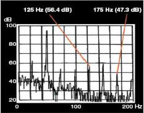
Figure 2. Current spectrum—short circuited turns in stator winding components are good indicators for detecting shorted turns in four-pole SCIMs with random-wound concentric coils. Note that these components will change in frequency as a function of load and speed, as reported. Note that a continuous MCSA system must be used to detect shorted turns on-line.
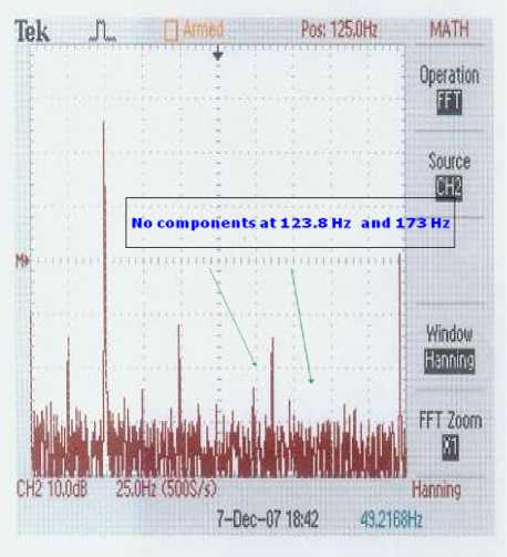
Figure 3. Stator current spectrum for Y – phase
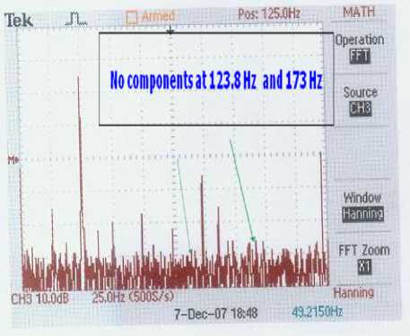
Figure 4. Stator current spectrum for B – phase
Figures 3 and figure 4 shows the Stator current spectra with no fault. The components that are clearly indicative of shorted turns are 125 Hz and 175 Hz as per (2) with k = 1, n = 3 and k = 1, n = 5. Note that the components at 25 Hz and 75 Hz are present under normal operation (the ± rotational speed frequency components) but cannot be used as indicators of shorted turns even although they are predicted from (2). There are no components at 123.8 and 173 Hz [no-load, slip is approximately zero for (2)] with no stator fault, but they are very evident at 56.6 and 42.3
dB, respectively, in the case with direct shorted turns. In, these components could also be detected at 27.7 and 23.6 dB, respectively, with one shorted turn (via a current limiting resistor to avoid initial burn-out).
-
b. Initial Experimental Tests (industrial motors)
Test Motor: An 2.2 kW, 400V, 4.5A, 1475 r.p.m., 50Hz, SCIM, delta connected, 36 slot stator was used for the tests. The stator winding has a 36 slot, 3 tier concentric winding with random wound coils (very commonly used in the 10 to 50 h.p. range by all manufacturers). One of the coils (in the R or A- phase) next to the input terminals of the motor was selected and tappings were made into a number of turns. The stator winding has 180 turns/phase which gives: Volts/tum = 2.34 V. The motor was run and the voltage across the tappings was measured as 2.36V and 4.64V which meant we had access to one turn and two turns in one coil of the A phase. To avoid initial bum out and failure the tests were initially carried out by connecting an external short circuit resistance (to limit the short circuit current) across one tum and then two turns. The case of one turn being short circuited is the minimum fault severity.[9] The current was monitored and analyzed via MCSA under various conditions to determine the effect on the components that are indicative of shorted tums; the following test conditions were initially investigated:
-
• No-load - no fault and one shorted turn in A-
- phase
-
• All phases were initially analyzed.
Initially the motor was tested on no-load (1498 r.p.m., accurate speed measurement). The slip on no-load is approximately equal to 0.016 but is taken to equal zero in the equations for predicting the current components at noload. This is also due to the fact that the MCSA Fast Fourier Transform resolution would not distinguish between components corresponding to slips of 0.016 and the approximation that the slip was zero on no-load. As a starting point consider the case for k=l, n=l in equation (1):
f st = (3/2)f 1 and f 1 /2 = 74.58 Hz and 25.415 Hz
It needs to be recognized that these components are also a function of air gap eccentricity. If these components were selected then it would not be possible to discriminate between shorted turns and air gap eccentricity problems. Consider a range of other components that are a function of shorted turns:
k=l, n=2, fsr =fi(l-s) and sfi , at s=0, we have : 99.17 Hz and 0
k=1, n=3, fst = 123.75 Hz and 23.75 Hz k=l, n=4, fst = 148.34 Hz and 48.34 Hz k=l, n=5, fst = 172.925 Hz and 72.925 Hz k=1, n=6, fst = 197.51 Hz and 97.51 Hz k=l, n=7, fst = 222.095 Hz and 72.095 Hz
The values will be slightly less than the frequencies given above since the slip s is taken to be zero rather than s = 0.016 on no-load.
No-load with no shorted turns - Analysis of spectra: Figure (3and 4) gives the line current spectra for the A-phase at no load and with no stator fault. The spectra for the B and C phases were the same as phase A. The FFT analyser was set to an 80dB dynamic range, using 64 linear spectrum averages and a frequency range of zero to 200Hz (400 line spectrum, 0.5Hdline) to capture the components up to 200Hz given by equation (1) for the 4-pole case. Examination of (1) shows there are components at 23.75 , 75, 100 and 150Hz from a perfectly healthy motor. Here is the evidence that a very careful analysis of the predicted components from classical theory needs to be considered in parallel with other sources of these components. The motor was driving a d.c. dynamometer load machine. The induction motor had inherent static and dynamic airgap eccentricity (total of 10% airgap eccentricity). This is a definite source of the 25 and 75 Hz components (usually defined as the rotational speed components). It has also been proved that any shaft misalignment also contributes to the magnitude of these components. Perfect alignment is not possible.
A 100 Hz component is also present. It is approximately 60dB (1000 times smaller) down on the main 50Hz component but is clearly visible in the spectrum. This component can be due to inherent asymmetry since perfectly symmetrical stator winding and magnetic circuits are not possible. Any unbalance in the supply voltage can also cause the 100 Hz component. The 150Hz component can be due to the B-H characteristic of the magnetic circuit. These components can therefore exist under no-load conditions and with no shorted turns. Power engineers who use MCSA must be aware that the dynamic range of modern spectrum analysers is excellent (80dB covers a linear scale of 10,000) hence information in the spectrum can be due to inherent asymmetry and not a fault. In the 4 pole case the 25, 75, 100 and 150Hz components should not be used as an indicator of shorted turns.
No-load with one shorted turn in R-phase - Analysis of Spectra:
Figures (5) shows the experimental arrangement which is made in induction motor for shorted of turns, figure 6 gives the line current spectra for all phases with one shorted tum in the A-phase. The short circuit current in the external short circuit was limited to 3.5A via an external resistance. The full-load phase current for the SCIM is : 4.5 A. (4.5A, line current, delta connected). The obvious change is that completely new current components exist at 125 and 175Hz and can only be due to the shorted turn, as per theory with k=l, n=3 and k=l, n=5 = 225Hz and 75Hz (equation (1)). This is the pronounced difference between Figures (1) and (2) to (4). Note that the 125 and 175Hz current components in each phase are, on average, 27dB and 23dB respectively, and of the order of 65 to 70dB down on the main supply component. With a direct short across a turn/s these components will be significantly larger since in the above tests the short circuit current was limited to 42.5A - this will be proved later.[9-10]
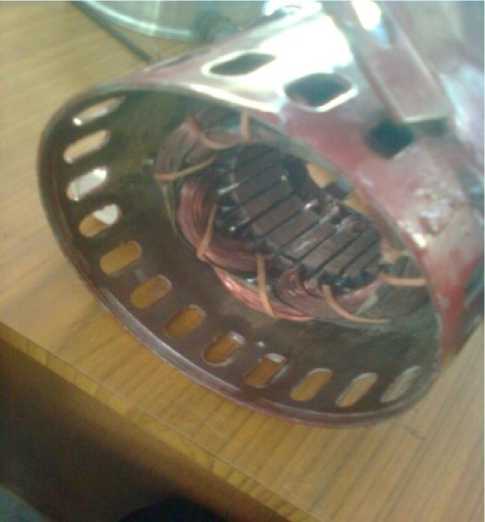
Figure 5. Experimental setup for shorted turns in induction motor
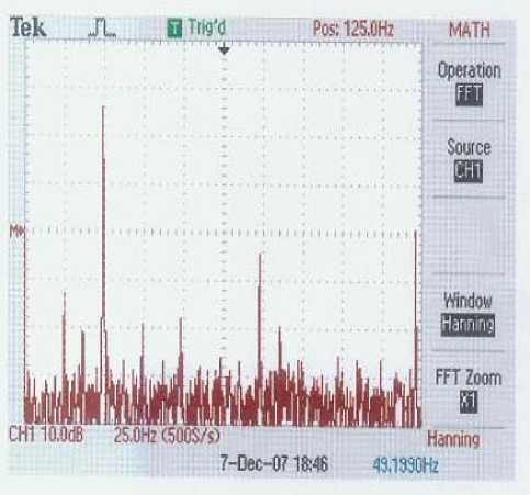
Figure 6. Stator current spectrum for R – phase
The 125 and 175Hz components are not harmonics of the supply frequency (not integer multiples) which means they cannot be confused with supply harmonics at noload. The components at 25, 75, 100 and 150Hz appear in the current spectra with no fault and with one shorted turn. All the line current spectra show the same signature pattern hence only one CT is required on any one of the three line conductors. This is a distinct advantage in industrial drives.
Figure.7 shows the Fast fourier transform spectra of induction motor for shorted turns using LabVIEW software in Block diagram.
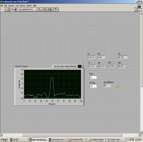
Figure.7 LabVIEW output for shorted turns
-
VI. CONCLUSION
The results in this paper have clearly demonstrated that MCSA can diagnose shorted turns for 2-pole and 4-pole, low voltage, SCIMs having either concentric or lap wound stators. Only one phase need be monitored hence only one CT is required. It has been proved that only certain current components should be selected from the classical theory to ensure reliable diagnosis of shorted tums. The results shows that the effect of load changes on the magnitude of specific current components with shorted turns is negligible compared to the change that occurs between zero shorted turns and shorted turns. This is not the case with stray flux monitoring. MCSA is sensitive enough to detect one or two shorted turns. Extensive field trials in industry will now be carried out on a wide range of low voltage induction motors.
References LabVIEW based Condition Monitoring of Induction Machines
- G.B. Kliman, W.J. Premerlani, R.A. Koegl, D. Hoeweler, A New Approach to On-Line Turn Fault Detection in AC Motors, in: IAS Annual Meeting, October 1996, 1996, pp. 687–693.
- J F Bangura and N A Demerdash: “Comparison between Characterization and Diagnosis of Broken BarslEnd-Ring Connectors and Airgap Eccentricities of Induction Motors in ASDs using a Coupled Finite Element-State Space Method, IEEE Transactions on Energy Conversion, Vol. 15, No. 1, March, 2000, pp 48-56
- William.T.Thomson and Mark fenger: "Current signature analysis to detect induction motor faults " - IEEE Transaction. On IAS Magazine, Vol , 7 , No .4 , pp , 26-34 , july / August 2001.
- S. Williamson, K. Mirzoian, Analysis of cage induction motors with stator winding faults, IEEE Trans. Power Apparatus Syst. PAS-104 (7) (1985) 1838–1842.
- William.T.Thomson and Ronald J. Gilmore : " Motor Current signature analysis to detect induction faults in Induction motor Drives – Fundamentals , Data Interpretation and Industrial case Histories " - proceedings of Thirty second turbo machinery symposium – 2003.
- M. Arkan, D. Kostic-Perovic, P.J. Unsworth, Online stator fault diagnosis in induction motors, IEE Proceedings: Electric Power Applications 148 (6) (2001) 537–547.
- YE Zhongming and WU Bin, "A Review on Induction Motor Online Fault Diagnosis" Ryerson Polytechnic University, Canada, IEEE, 2000
- Tom Bishop " Squirrel cage Rotor Testing", EASA Convention 2003, Moscone convention Centre , San Francisco, CA June 30, 2003
- Tavner. P. and Penman .J.,Condition Monitoring of Electrical Machines, Research Studies Ltd., London, England John Wiley & Sons.
- Peter Vas, “Parameter estimation, condition monitoring and diagnosis of electrical machines”, 1995.
