Learning Computer Network by Writing Your Own Protocol Analyzer

Author: Zhi Chen, Chunmiao Yuan, Na Sun
Journal: International Journal of Education and Management Engineering(IJEME) @ijeme
Article in issue: 10 vol.2, 2012.
Free access
Computer network is one of the fundamental courses for college students majoring in CS, CSE and EECS. The objective of this course is to explain the basic principles and architecture of network based on TCP/IP. However, many students find the course quite abstract and difficult to understand. Inspired by the idea of "learning by doing", we propose a learning approach by asking the students to design and to implement their own protocol analyzer during the course. This task not only synthesizes the knowledge of all the important protocols ranging from data link layer to application layer, but also bridges the gap between theory and practical aspect. Promising feedbacks from students demonstrate that this method is very helpful for student to study computer network.
Computer network teaching, protocol analyzer, Libpcap/WinPcap
Short address: https://sciup.org/15013757
IDR: 15013757
Text of the scientific article Learning Computer Network by Writing Your Own Protocol Analyzer
Published Online October 2012 in MECS DOI: 10.5815/ijeme.2012.10.01
The benefits of this approach are helping students:
-
• Obtain solid understanding of hierarchical network architecture and firm memory of common protocol formats.
-
• Strengthen programming ability, especially network programming skills.
-
• Develop the habit of using protocol analyzer to identify and solve network problems.
-
• Facilitate the study of new network protocols and technologies.
-
2. Content of computer network
The content of the computer network commonly consists of introduction, principle of the communication, hierarchical architecture of network and other related knowledge. Since TCP/IP protocol suite has been widely applied in the Internet, hierarchical architecture of network based on TCP/IP has become the most important component of the network course. First, we will simply introduce the five-layered architecture of computer network and typical protocols in each layer as shown in Fig. 1 and in [3][4].
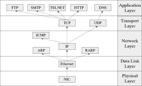
f igure 1. TCP/IP five-layered architecture
-
A. Physical Layer
The Physical Layer is the first and lowest layer in the five-layer model of computer network.
The Physical Layer is a fundamental layer which consists of the basic hardware transmission technologies of the network. The Physical Layer defines the ways of transmitting raw bits rather than logical data packets over a physical link connecting network nodes.
-
B. Data link layer
The Data Link Layer transfers data between adjacent network nodes in a wide area network or between nodes on the same local area network segment. The Data Link layer ensures that an initial connection has been set up, divides output data into data frames, and handles the acknowledgements from a receiver that the data arrived successfully. It also ensures that incoming data has been received successfully by analyzing bit patterns at special places in the frames. Protocols of data link protocols are the Point-to-Point Protocol (PPP), Ethernet v2 for local area networks, HDLC and etc.
-
C. Network Layer
The Network Layer is responsible for end-to-end (source to destination) packet delivery including routing through intermediate hosts. It provides the functional and procedural means of transferring variable length data packages from a source to a destination host via one or more networks while maintaining the quality of service and error control functions. Besides the IP, TCP/IP includes the ARP, RARP, ICMP and IGMP.
-
D. Transport Layer
Transport Layer is responsible for encapsulating application data blocks into data segments suitable for transmission to the destination host. Two protocols in Transport Layer are Transmission Control Protocol (TCP), which provides reliable data transmission and congestion control, and User Datagram Protocol (UDP), which only provides best-effort delivery.
-
E. Application Layer
-
3. Design and Implementation of Protocol Analyzer based on LibPcap/WinPcap
Application Layer provides services for an application program to ensure that effective communication with another application program in a network is possible.
For the final course project, the students are asked to write their own protocol analyzer, which captures, parses and displays the content and format of packets, based on Libpcap[1] in Linux/Unix platform, or based on WinPcap[5] in Windows platform.
-
A. Program Architecture
Since most of local area network up-to-date is built on Ethernet and most PCs or laptops are equipped with Ethernet adapter, we assume the program to be run in Ethernet environment. As guidance, we propose a simple protocol analyzer, which consists of three parts: Packet Capture Module, Protocol Analyzing Module and User Interface, illustrated by Fig. 2.
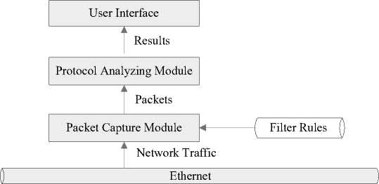
f igure 2. Architecture of protocol analyzer
Packet Capture Module takes the responsibility of capturing network traffic that can be heard by Ethernet network interface card (NIC), and then feeds the Protocol Analyzing Module with various types of captured packets for parsing. User Interface, which accounts for displaying results, is independent from the other two modules and can be implemented either in command line mode or GUI mode. In addition, we also support filter rules to filter out unwanted traffic.
Apart from the design mentioned in this paper, we also give the students freedom to customize their software architecture, so long as the resulting programs include all the required functions.
-
B. Packet Capture Module
Packet Capture Module is the corner stone of a protocol analyzer. Libpcap provides implementationindependent access to the underlying packet capture facility provided by operating system[6]. This library is originally implemented in Linux/Unix platform, and then ported to Windows platform as WinPcap. In short, we use Libpcap/WinPcap library to grab packets from the network card directly. The typical using steps are presented in Fig. 3.
-
1) Retrieve the list of network devices.
-
2) Open user designated network device in promiscuous mode.
-
3) Initiate capture filter according to filter rules.
-
4) Capture and parse packets .
-
5) Close network device.
It is worthy of pointing out the powerful filter engine of Libpcap/WinPcap. Filter rules are represented in Boolean expression with built-in keywords. And there are mainly 4 types of keywords:
-
1) protocol, including arp , ip , icmp , tcp and udp
-
2) MAC address, like ether ;
-
3) IP address, like host
-
4) port, like port
For example, to capture TCP packet with 192.168.0.112 as source or destination IP address, with 80 as source or destination port number, we set filter expression to: ( ip and tcp ) and ( host 192.168.0.112) and ( port 80) .
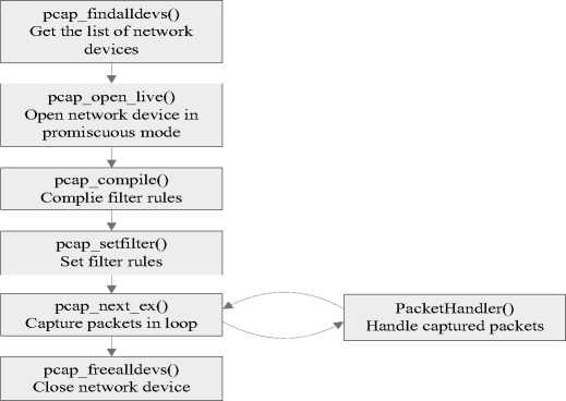
f igure 3. Control flow of packet capture using WinPcap
-
C. Protocol Analyzing Module
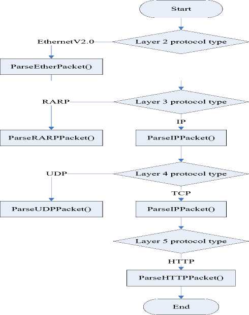
This module is in charge of parsing captured packets, which, to some extent, can be viewed as a mimic handling process of network stack. In order to analyze the packets, we decode header of each layer one by one in a bottom-up fashion, starting from data link layer to application layer, as Fig. 4 illustrated.
Analyzing process starts from Ethernet frame in layer 2. There are two existing standards for Ethernet frame format: Ethernet Version 2 and IEEE802.3, distinguished by the value of Type field in frame header.
According to the value of Type field, we delivery the payload of Ethernet frame to appropriate layer 3 protocol handlers, such as IP, ARP and RARP to name a few. We use IP as an example to illustrate the implementation of protocol parsing. To represent the format of IP header, showed in Table 1, we define an IP HEADER structure:
|
//IP header format |
||
|
typedef struct |
||
|
{ |
||
|
unsigned char |
hdr_len:4; |
//4-bit header length |
|
unsigned char |
version:4; |
//4-bit version number |
|
unsigned char |
tos; |
//8-bit type of service |
|
unsigned short |
total_len; |
//16-bit total length |
|
unsigned short |
identifier; |
//16-bit identification |
|
unsigned short |
frag_and_flags; //3-bit flags and 13-bit fragment offset |
|
|
unsigned char |
ttl; |
//8-bit time to live |
|
unsigned char |
protocol; |
//8-bit upper protocol |
|
unsigned short |
checksum; |
//16-bit header checksum |
|
unsigned long |
source_ip; |
//32-bit source IP address |
|
unsigned long |
dest_ip; |
//32-bit destination IP address |
|
} IP_HEADER; |
||
IEEE802.3
Parse8023Packet()
ARP
ParseARPPacket()
ICMP
ParseICMPPacket()
f igure 4. Control flow of protocol parsing
T able 1. F ields of IP header
0 4 8 16 31
|
Ver |
IHL |
Tos |
Total length |
|
|
Identification |
Flags |
Fragment offset |
||
|
TTL |
Protocol |
Header checksum |
||
|
Source IP address |
||||
|
Destination IP address |
||||
|
Options |
||||
Then we extract and interpret the value of each field in the IP header of the captured packet and fill in the corresponding field in IP_HEADER structure. Finally, the resulting IP_HEADER structure, which stands for the outcome of protocol analysis, is passed to User Interface module to generate a user-friendly display, shown in Fig. 6. Layer by layer, we parse each protocol header in the same way as IP. Primarily, we implement several typical protocols ranging from layer 2 to layer 5 shown in Fig. 4, and we also encourage student to support more protocols within the framework.
-
4. Application of Protocol Analyzer
Apart from statically examining protocol format (such as IP, TCP and HTTP) of a single packet, students are highly motivated and interested in applying their own protocol analyzer to scrutinize network traffic, so that they can better understand the dynamic interaction of network protocols and internal mechanism of network applications and commands. Next, we are going to show how to analyze three-way handshake and Tracert command by using our own protocol analyzer.
-
A. Analyzing of the three-way handshake
The three-way handshake in TCP is the method used to establish network connections. With TCP handshaking mechanism, two computers attempting to communicate can negotiate the parameters for the connection before starting communication.
Below is a simplified description of the TCP 3-way handshake process.
-
1) Host A sends a TCP SYNchronize packet to Host B.
-
2) Host B receives A's SYN.
-
3) Host B sends a SYNchronize-ACKnowledgement.
-
4) Host A receives B's SYN-ACK.
-
5) Host A sends ACKnowledge.
-
6) Host B receives ACK. TCP connection is ESTABLISHED.
Fig. 5 shows the process of three-way handshake of TCP recorded by our own protocol analyzer. In this scenario, we visited the web page of , whose IP address is 119.75.213.50. The client IP address is private 192.168.0.112.
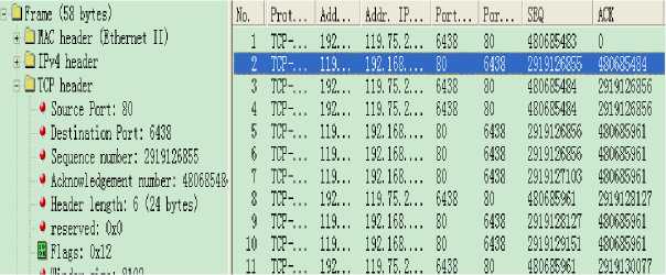
f igure 5. Three-way handshake of TCP
The real three-way handshake process is demonstrated by Fig. 5 as following.
-
1) The First handshake (requirement of connection) is from client to server. We can see that seq is 480685483 and SYN = 1.
-
2) The second handshake (acknowledgement of setting up the connection) is from server to client. We can find seq is 2919126855, ack is 480685484, SYN = 1 and ACK = 1.
-
3) The third handshake (acknowledgment of the connection) is from client to server, seq is 480685484, ack is 2919126856 and ACK=1.
-
B. Analyzing of Ping and Tracert
Both Ping and Tracert (the counterpart of Traceroute in Windows platform) commands are useful tools for network diagnosis. Ping command sends ICMP “echo request” packets to the target host and waiting for ICMP “echo response” replies. Tracert command also exploits ICMP messages to discovery all the routers on the path from source to destination. Due to lack of space, we only show the captured packages when we tracert , in Fig. 6.
В (J IPv4 header
^ Version: 4
♦ Header length: 5 (20 bytes)
Hl Type of service (TOS): 0x00 t Total length: 92 bytes
** Identification: 58053
HI Flags: 0x00
Г^ПтеtoН"е^ТлЗТ1ГнпрЁП
2 Checksum: 0xC545 (Correct)
S Source IP address: 192.168.0
S Destination IP address: 119.
^ IP options = None
- I OP hmdnr-------------
; * Type: 8 (Echo Request)
I ^ Code: 0
У Checksum: OxSIFF
|
35 |
IP |
ICJIP->Echo Request |
192.168. 0.112 |
119. 75.213. 50 |
|
36 |
IP |
ICJIP->Time Exceed |
117. 8. 3.149 |
192.168. 0.112 |
|
37 |
IP |
ICJIP->Echo Request |
192.168. 0.112 |
119. 75.213. 50 |
|
38 |
IP |
ICJIP->Time Exceed |
117. 8.1.5 |
192.168. 0.112 |
|
39 |
IP |
ICJIP->Echo Request |
192.168. 0.112 |
119. 75.213. 50 |
|
40 |
IP |
ICJIP->Time Exceed |
117. 8.1.5 |
192.168. 0.112 |
|
41 |
IP |
ICJIP->Echo Request |
192.168. 0.112 |
119. 75.213. 50 |
|
42 |
IP |
ICJIP->Time Exceed |
117. 8.1.5 |
192.168. 0.112 |
|
43 |
IP |
ICJIP->Echo Request |
192.168. 0.112 |
119. 75.213. 50 |
|
44 |
IP |
ICJIP->Time Exceed |
202. 99.66. 205 |
192.168.0.112 |
|
45 |
IP |
ICMP->Echo Request |
192.168. 0.112 |
119.75.213. 50 |
|
46 |
IP |
ICMP->Time_Exceed |
202. 99.66. 205 |
192.168.0.112 |
|
47 |
IP |
ICMP->Echo Request |
192.168. 0.112 |
119.75.213.50 |
|
48 |
IP |
ICMP->Time Exceed |
202. 99.66. 205 |
192.168.0.112 |
|
49 |
IP |
ICMP->Echo Request |
192.168. 0.112 |
119.75.213. 50 |
|
50 |
IP |
ICJIP->Time Exceed |
219.158.13.253 |
192.168.0.112 |
|
51 |
IP |
ICMP->Echo Request |
192.168. 0.112 |
119.75.213. 50 |
OOOO 00 21 91 42 C4 DO ОО 1A 73 38 7F CA 08 00 45 00 .!,B....s8...,E.
f igure 6. Captured result of tracert command
In Fig. 6, we conclude that Tracert command sends a serial of ICMP “echo requests”. TTL in initial request is set to 1, and the value is increased by 1 for each successive request. Intermediate routers report ICMP “time exceed” responses as the result of TTL diminishing to 0. The fact that we don’t see any TCP or UDP information means Tracert command generates ICMP packets directly without interfering transport and application layers.
As a result, students are keen on applying their own protocol analyzer to check popular network applications and socket programs that they write during the course. Some students even write their own Ping and Tracert program and form their self-made network diagnostic toolkit.
-
5. conclusion
In this paper, we propose a new computer network teaching approach which is featured by giving the students an assignment of writing their own protocol analyzer, and encouraging them to apply it as much as possible. Concrete program greatly embodies the abstract network concepts, makes difficult subject easier to understand and digest. Using this method, we are successful not only in attracting students' interests in learning network knowledge, but also in yielding prominent improvements in their learning ability and effectiveness.
References Learning Computer Network by Writing Your Own Protocol Analyzer
- http://www.tcpdump.org/
- http://www.wireshark.org/
- A. Tanenbaum, Computer Networks, 4ed., Prentice-Hall, 2003.
- J. Kurose and K. Ross, Computer Networking: A Top-Down Approach Featuring the Internet, 4ed., Pearson Education, 2008.
- http://www.winpcap.org/
- R. Stevens, Unix Network Programming.Volume.1, 3ed Addison-Wesley,2003.
