Mathematical model of the damping process in a one system with a ball vibration absorber

Author: Zhengbing Hu, Viktor Legeza, Ivan Dychka, Dmytro Legeza
Journal: International Journal of Intelligent Systems and Applications @ijisa
Article in issue: 1 vol.10, 2018.
Free access
The forced oscillations of the damping mechanical system of solids "Ball Vibration Absorber (BVA) with linearly viscous resistance – a movable carrier body" under the influence of external harmonic excitation are considered. Based on Appell's formalism, the dynamic equations for the joint motion of a heavy ball without sliding into a spherical cavity of a carrier body are formulated and numerically studied. The amplitude-frequency characteristic of the damping mechanical system and the curves of the dependences of the maximum amplitude of the oscillations of the carrier body on the values of the radius of the spherical cavity and the coefficient of viscous resistance of the BVA are obtained. The conditions and restrictions on the rolling of a heavy ball in the spherical recess of the absorber without sliding are determined.
Damping Mechanical System, Carrier Body, Working Body, External Harmonic Excitation, Ball Vibration Absorber (BVA), Kinematic Ties, Nonholonomic Ties, Appell's Formalism, Amplitude-Frequency Characteristic (AFC), Parameters Settings of Absorber, Determining the Optimum Parameters, Rolling of a Heavy Ball Without Sliding
Short address: https://sciup.org/15016451
IDR: 15016451 | DOI: 10.5815/ijisa.2018.01.04
Text of the scientific article Mathematical model of the damping process in a one system with a ball vibration absorber
I. Introduction. The Current State of the Problem and Suggestions for its Solution
When processing the operating load-bearing objects (such as height flexible buildings and structures, industrial and transport machinery and mechanisms, cable-stayed bridges, power lines, etc.), often there are forced oscillations of their individual elements or the objects themselves. The consequence of this is additional dynamic loads and impacts on these load-bearing objects, they fight against which turns into a big technical problem.
The nature of the emergence of forced oscillations is diverse. For example, wind, seismic, industrial, hydrodynamic, transport, other force, or kinematic influences can be classified as such. Forced oscillations can disrupt the normal operating conditions of the elements of mechanical systems, and the associated dynamic loads create a direct threat to their strength, reliability and stability.
To suppress forced vibrations of flexible and extended objects, various dynamic vibration dampers use [1 – 9, 14, 17, 19 – 21, 23 – 25]. Structurally, existing vibration dampers can be divided into three main groups: spring, pendulum, shock [1 – 9, 22, 25]. However, their dynamic behaviour and correct application in the vibration protection system is clearly regulated by the relevant regulatory documents only in certain frequency ranges of carrier objects [1, 2, 8].
Due to its dynamic characteristics and the functional purpose, a significant number of the above extended large objects have their own fundamental frequencies, which range from 12 rad/s to 3 rad/s and below. For example, this applies to modern high-rise structures such as TV towers. In this case, the design solutions of the absorbers essentially depend on the level of the natural frequencies of the fundamental tone of the oscillations of carrier objects. Depending on their size, the absorbers can be divided into three main groups with varying frequency bands [1, 2]:
-
• high-frequency range: 5 – 12 rad/s;
-
• mid-range: 3 – 5 rad/s;
-
• low-frequency range: below 3 rad/s.
Spring dampers are usually used for vibration protection of objects in the mid-frequency and high-frequency ranges with small oscillation amplitudes, so it is physically impossible to use them at low frequencies (up to ω ≤ 3,0 rad/s) and high amplitudes ( 1 - 3 m) [1, 2, 6, 8].
Acceptable dampers for medium frequencies are the pendulum absorbers mentioned above. At frequencies above 5 rad/s on pendulum absorbers it is necessary to install elastic elements.
The use of pendulum dampers is completely determined by the length of the suspension of the working body of the pendulum [1, 2, 8, 25]. At small natural frequencies, the length of the suspension of their working bodies is significantly increased, and the amplitude of the oscillations can exceed the transverse dimensions of the carrier object itself. On the other hand, as a rule, the working space for placing, fixing and functioning of the absorber is limited both vertically and horizontally, therefore, the significant dimensions of the pendulum dampers exclude the possibility of their use for vibration protection of carrier objects in the low-frequency range.
Shock absorbers on these objects (for example, on TV towers or radio masts) are generally not recommended because of the attendance of maintenance personnel and the availability of precise equipment and transceiver equipment [1, 2, 8].
Thus, to solve the problem of vibration protection of carrier objects in the low-frequency range, fundamentally new design solutions of absorbers should be sought that will significantly reduce their dimensions while maintaining the same pendulum nature of their functioning [8, 14, 19 – 21].
At the same time, the conditions of operation of the absorbers are characterized by the fact that their structures cannot be under constant supervision. In this regard, they must be functionally simple and resistant to the external effects of atmospheric phenomena, turning into a permanent working element of a carrier object (for example, a high-altitude structure).
Recently, alternative designs of dynamic absorbers have been developed, in which other principles of suppression of forced oscillations are used. They are based on the provision of large mutual displacements of carrying and working bodies in various directions. To realize such displacements, the most successful mechanical systems with rolling without sliding of certain solids over the moving surfaces of other bodies (so-called rolling-damping systems). One of the authors was one of the first to drew attention to the possibility of using such systems for dampening shock on transport and vibration suppression of forced vibrations of load-bearing bodies [10 – 13]. In such systems with rolling, the oscillating motion of solids is limited by kinematic tiers. The analytical consideration of these tiers requires new approaches and methods for constructing and studying mathematical models that correctly describe the dynamic processes of vibration suppression of forced vibrations of load-bearing bodies.
In the domain of the dynamics of bound rigid bodies, nonholonomic problems were previously considered in which dynamic effects associated with the proper motion of heavy balls and cylinders over fixed algebraic surfaces of the second order were studied [16, 18], as well as the dynamic behaviour of other mechanical systems bounded by nonholonomic constraints [15]. However, the influence of oscillating motions of heavy balls and cylinders (as working bodies of absorbers or their elements) on mobile carrier bodies and the dynamic effects of vibration suppression connected with this motion have not been considered at all until recently.
In this connection, we note several papers [14, 17, 19 – 21, 23, 24], aimed at studying the dynamics of damping systems of load-bearing bodies with a spherical absorber of forced oscillations (Ball Vibration Absorber - BVA). The effects of suppressing forced oscillations of a carrier object using BVA consists in rolling a heavy ball without sliding on spherical recess with a constant radius laid out by a special flexible material with a high coefficient of friction. Simultaneously, this flexible material plays the role of an uncontrolled friction-damping device for suppressing the oscillations of the heavy ball in the notch. In this case, the ball movement with proper tuning must occur in antiphase with respect to the motion of the carrier body. The ball has a radius r smaller than the radius R of the spherical recess BVA, and is a BVA working body with a relatively large mass. The difference R = R - r between these radii is the main regulating parameter of the natural frequency ω of the spherical absorber, which for small oscillations of the ball in the recess is determined by the formula:
ω abs = 1,4 R .
Therefore, for carrier objects with natural frequency from the interval ω ≤ 3,0 rad / s , it is necessary that the
BVA parameter R is in the interval: R ≥ 0,78 m .
The main constructive disadvantage of BVA-absorbers is the non-isochronism of vibrations of the working body (ball) in the spherical cavity. Namely, at low frequencies (up to ω ≤ 3,0 rad / s ) of the carrier body and large relative displacements ( 1,0 - 3,0 m) of the BVA working body, this significantly affects the quality of its functioning. However, with small relative movements of the working body, the BVA may well work in the normal mode of vibration protection of the carrier objects. In addition, there is another design disadvantage of BVA-absorbers. The flexible material with which the spherical cavity is lined loses its frictional-dampening properties and the absorber ceases to function as a damper.
As for the essence of the research [14, 17, 19-21, 23, 24], there is one significant omission in them: they do not say anything about the conditions and restrictions on the
"clean" ball rolling in the spherical cavity of the absorber, and has not been studied the possibility of tearing the ball away from the spherical surface of the recess. But these conditions are an important theoretical basis of physical realizability and a justification for the adequate functioning of such absorbers. In addition, they do not offer a technique for determining the optimal settings for the BVA-absorber.
Thus, the lack of appropriate theoretical basis for justifying the dynamic behaviour of damping systems with cat-and-dampening devices (considering the specificity of their movement) hampers their widespread introduction into modern practice of vibration protection of load-bearing objects. At the same time, experimental studies of the dynamic behaviour of roller mechanisms in vibration protection systems used in shipbuilding, transport engineering, and earthquake-proof construction have proven their high efficiency.
In this paper we consider the simplest type of damping system, which consists of a ball absorber with an adjustable linear viscous resistance. A dynamic problem of this class belongs to the class of problems of nonholonomic mechanics. Therefore, a special methodical approach based on the Appell’s formalism was used to construct the equations of motion of the damping system under investigation [16, 18].
This work is a continuation of the studies initiated by one of the authors about the creation of a new class of roller absorber and published earlier in articles [10 – 13].
II. Statement of the Problem and Research Purposes
The dynamics of the damping mechanical system of two coupled solid bodies is considered “VBA with a viscous resistance – a movable carrier body”, which is under the action of an external periodic action (Fig.1). The effect of vibration protection of BVA is based on the rolling of a working body in the form of a heavy ball with mass m and radius r without sliding in a spherical cavity with a radius R . The latter is rigidly connected to the carrier body and, together with it, has mass M . The body moves horizontally along the axis OX . This movement is impeded by a system of elastic elements with an equivalent stiffness coefficient k and viscous dampers with a coefficient of viscous resistance C .
The effect of vibration protection of BVA is based on the rolling of a working body in the form of a heavy ball with mass m and radius r without sliding in a spherical cavity with a radius R . The latter is rigidly connected to the carrier body and, together with it, has mass M . The body moves horizontally along the axis OX . This movement is impeded by a system of elastic elements with an equivalent stiffness coefficient k and viscous dampers with a coefficient of viscous resistance C .
A heavy ball with a weightless spherical clip connected to the body carrying system of adjustable air dampers. On one hand, the rods of air dampers are hingedly connected to the spherical cage of the heavy ball, and on the other hand to the carrier body. This spherical cage without friction interacts with the heavy ball. This pair creates a spherical hinge that works in any horizontal direction, passing the interaction forces to the air dams, which in turn transmit them to the carrier body and vice versa.
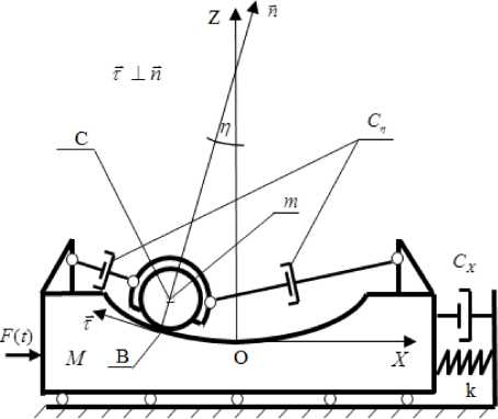
Fig.1. The scheme adopted for modeling the dynamic behavior of a damping system with a BVA
During the simulation, the dampers operating in one longitudinal direction were replaced by a single damper with an equivalent viscous friction coefficient C . The resistance force of such an equivalent damper is determined by the linear function of the relative velocity of the centre of mass of the ball: Fn = C • R -q. The mass of air dampers is not considered.
The external force acts on the carrier body, which is described by a harmonic function with a stable carrier frequency to :
F (t) = F • sin (to-1) (2.1)
This design of the BVA-absorber is distinguished from the known ones in it is possible to control the level of damping of the absorber's working body.
The purpose of the work is:
-
1) to construct a mathematical model of the process of vibration suppression of forced oscillations of a carrier body using a ball absorber;
-
2) to determine the conditions and restrictions on the "clean" rolling of the ball in the spherical recess of the absorber, thereby justifying the possibility of the physical application of such roller systems as vibration dampers;
-
3) to evaluate the efficiency of the proposed absorber.
We now turn to the formulation of geometric and kinematic relations, which will be used in further transformations.
III. Geometric and Kinematic Relations
We denote by n the vector of the inner normal drawn at the point B – contact point of the sphere and the spherical cavity. We introduce two independent generalized coordinates for the two-mass system under investigation: x – displacement of the centre of mass of the carrier body M along the axis OX ; q — angle of deviation of the inner normal n from the vertical axis OZ ( - П 2 5 n 5 .) .
The coordinates of the internal normal vector are expressed by the angle of its deviation from the vertical OZ (Fig.1):
n = ( sin ( n ) ;0;cos ( n ) ) (3.1)
We write the vector kinematic equation, which follows from the non-sliding condition for the sphere relative to the spherical surface of the recess:
V = x - i + ф-j x r - n (3.2)
where ф - is the angular velocity of the sphere relative to its centre of mass; r – is the radius of the ball; V – the linear velocity of the centre of mass of the ball, V n = ( x n ; 0; z n ) ; R - radius of the spherical surface of the recess.
We rewrite (3.2) in a scalar form considering the introduced generalized coordinates, formula (3.1), and the fact that, ф - r = n - R , where R = R - r . This follows from the non-sliding condition of the ball with the centre of mass at the point C with respect to the movable spherical recess at the point B . Here it should be emphasized that the vectors ф - j and q- j are directed in opposite directions, therefore the angular velocities ф and n have different signs:
/ xn = x - R • cos ( n H;
_zn = R • Sin(n)"n. "
We now turn to the derivation of the equations of motion of the investigated vibration protection system. To do this, we use the Appell’s formalism for nonholonomic systems [16, 18].
IV. Construction of the Equations Of Motion of the Damping System
In a general form, we write 5 - the function of the energy of the accelerations of all masses of the system [16, 18]:
p M ■ x2 m • ( x n + z n ) J -ф2
5 =---+ ——--— + ——
(4.1)
where J = 0,4 • m - r2; |ф| = —- Щ .
r
Considering (3.3), we define all the second derivatives that enter into expression (4.1):
xn = x-R -(n - cos(n)~n2 * sin(n)), (4.2)
zn = R -(n • sin(n) + n2 • cos(n)) . (4.3)
We substitute the obtained expressions (4.2) and (4.3) into (4.1) and consider only those terms of the acceleration function S , which depend on the second derivatives of the generalized coordinates x and n . The function thus obtained is denoted by 5 * :
5* = M + m * x 2 + 0,7 * m - R 2 n 2 +
+m - R - x -(n2 - sin(n)-n - cos(n)) . (4.4)
We write Appell's equations in a general form:
dl = P.; д5_ = P dx d n
(4.5)
We define the right-hand sides of Appell's equations P , P related to independent generalized coordinates x and n . To do this, we write down the expressions for the sum of elementary works 5 А , noting that the mechanical system moves under the action of the following force factors:
-
1) the force of gravity, which acts on the heavy ball,
P ball =- mgk ;
-
2) a viscous resistance whose modulus of the vector is equal Fn = Cn - R - n and which acts on the heavy ball in the direction opposite to the vector V - VM ; where VM - the vector of the linear velocity of the centre of mass of the carrier body, and V - the vector of the linear velocity of the centre of mass of the heavy ball;
-
3) elastic force FSP =- k - x • i , which acts on the carrier body;
-
4) viscous resistance Fx = -Cx • x • i , which acts on the carrier body;
-
5) external periodic force acting horizontally on the carrier body; its modulus is F ( t ) = F o - sin ( ^ - 1 ) .
In this problem, the work of the reaction of the kinematic tie at the point B is zero, since the virtual displacement of this point is zero due to the absence of slippage. Therefore, the expression 5 А has the form:
5 A = ( F ( t ) — k • x — Cx • x ) • 5 x —
— C n • R 2 -n^n — m • g • 5 z n . (4.6)
Considering the relation (3.3), the expression (4.6) in the variations of the generalized coordinates takes the following form:
5 A = ( F ( t ) — k • x — Cx • X ) • 5 x —
-
— C • R2 n* 5n~ m • g • R • sin ( n ) • 5n . (4.7)
On the other hand, the expression for the sum of elementary works 5 А through generalized forces P , P assigned to independent generalized coordinates, x and П , thus, write:
5A = p 5x + p -in (4.8)
Using the relations (4.7) and (4.8), we obtain expressions for P , P :
p = F(t) — k • x — Cx • x , (4.9)
P = — C ^ • R2 n — m • g • R • sin ( n ) . (4.10)
We differentiate expression (4.4) in accordance with equations (4.5) and consider relations (4.9) and (4.10) in the right-hand sides of equations (4.5). As a result, after some transformations, we obtain the following equations of motion for the mechanical system under investigation in generalized coordinates x and n :
( m + M ) • x + k • x + Cx • x +
+m • R П2 • sin(n) — П* cos(n)) = F(t) , (4.11)
C
cos(n)• x —1,4• R • n = — -Rn +g•sin(n). (4.12)
m
We divide by M the first equation of system (4.11) – (4.12). Let us write down the final system of nonlinear differential equations of motion of the vibration protection system in new notation, based on which we will carry out further investigations:
( 1 + v ) x + 2 nx • x + to 2 • x +
+v •R •(sin(n)n2 — cos(n)n) = F° •sin(to^ t) , (4.13)
cos( n ) • x = 1,4 • R n + 2 n 7 • R n + g • sin( n ), (4.14)
where;
-
2 k . C . Cn - F
to 2 = — ; 2 nx = —; 2 n = —; f ° = ~° ;
° M M n m M
m v = —
M
.
V. Numerical – Graphical Method for Determining Optimal Settings for Ball Absorbers (Linear Model)
Using the known methods [8, 22] for determining the frequency response for linear problems, we write the final AFC equation A = A ( to ) in explicit form for the problem in a linear formulation (here no intermediate computations are given):
A(to) = fJ X F7(to) / x , (5.1)
V ' ^ F8 (to) + F9 (to) + F (to) v 7
where F 1 ( to ) = 2 nx to ; F 2 ( to ) = g — 1,4 R to 2 ;
F3 (to) = 2nnRto; F4 (to) = F1 (to)F3 (to) — F2 (to)Q(to);
F5 (to) = vRto4 ; Q(to) = to2 —(1 + v)to2;
F6 (to) = Q2 (to) + F12 (to); F7 (to) = F2 (to) + F32 (to);
F 8 ( to ) = F 6 ( to ) F 7 ( to ) ; F 9 ( to ) = 2 F 4 ( to ) F 5 ( to )
F1° (to) = F52 (to) .
Let's briefly outline the essence of the numerical-graphical method for determining the optimal tuning parameters of BVA-absorbers. It is based on the principle of "equality of two maxima" AFC [5, 8, 22], which are achieved at two main frequencies to 1 and to 2 located near the fundamental frequency to 0 of the carrier body. With the optimum setting of the absorber, the frequency response curve of the system must have a form symmetrical with respect to the frequency ш = ^ Li ^ 2 with two peaks equal in amplitude at the two indicated frequencies to 1 and to 2 . One of the maxima of the curve A = A ( to ) corresponds to the reduced mass M of the carrier body, and the other to the mass m of the working body of the absorber.
As parameter settings for the BVA-absorber are considered: the geometric characteristic R = R — r and the damping factor n n of its working body. The value of
m the absorber's mass parameter v = — is assumed to be set and equal v = 0,05.
A numerical implementation was carried out for a concrete vibration protection system with the following parameters: to 0 = 1,3 rad / s ; F o = 0,03 g ; v = 0,05 ; nx = 0,03 s — 1.
The result of determining the optimum value of the damper parameter R using the numerical-graphical method is shown in the graph (Fig.2).
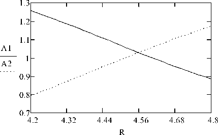
Fig.2. Determining the optimum value of the absorber parameter R for a linear model
First, we determine the frequencies to and ® 2 , at which two AFC maxima for a linear system are reached, according to [5, 8, 22]:
/ 122 =

to 2
, where / 1 2 = —— . (5.1)
, ® 0
Next, we graphically determine the point of intersection of fragments of curves A and A , constructed for two fixed frequencies ( to = 1,1654 rad / s and to = 1,3641 rad / s ) with a change in the BVA parameter R , at which the function A = A ( to ) reaches two equal maxima. The value at which this intersection takes place determines the optimal value of the BVA parameter ( R = 4,559 m ).
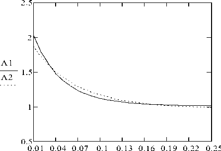
Now, we proceed to determine the optimum value of the damping coefficient n using the proposed graphical method. We use the same frequencies to and ® 2 , on which two maximums of the AFC are reached, and the value of the above-defined frequency parameter of the absorber ( R opt = 4,559 m ). The graph (Fig.3) shows fragments of the curves A and A constructed for two fixed frequencies to and to with a change in the damping coefficient n of the absorber's working body.
As we can see, the intersection of the curves A and A is achieved in two places – for larger and smaller amplitudes. We choose a variant with a smaller amplitude, and the required damping coefficient will have a value of n n = 0,18 s 1 .
Now, we construct the resulting graph of the amplitude-frequency characteristic (Fig.4) of a damping system with optimally selected ball absorber parameters R = 4,559 m and n n = 0,18 s 1 (in a linear setting). The AFC graph clearly shows that it has two equal maximum amplitudes of the carrier body, each of which is equal
A max = 1,03 m .
n n
Fig.3. Determining the optimum value of the absorber parameter n for a linear model
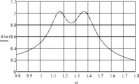
Fig.4. AFC of the suppression system with the optimal parameters of the absorber (linear model)
For comparison, we graph the frequency response of a mechanical system without an absorber, i.e. for the case when the mass of the working body (ball) is zero (Fig.5). In this case, the maximum amplitude reaches a value A max = 3,774 m .
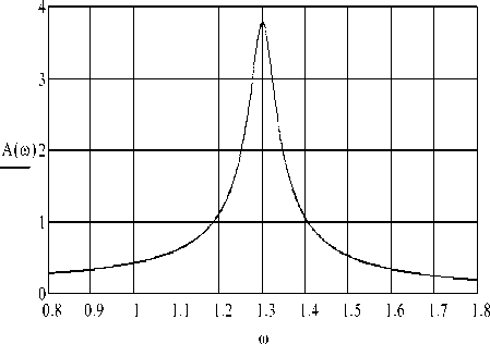
Fig.5. AFC of the system without an absorber
Comparing the maximum amplitudes in graphs 5.3 and 5.4, we are convinced of a significant decrease in the level of the amplitudes of the forced vibrations of the carrier body under the condition that the absorbers of this type are optimally applied.
All that was said above was possible under the condition of rolling a heavy ball without sliding occurs in the spherical recess of the supporting body. Therefore, an important integral task of this study is to determine the conditions for ensuring and realizing the “pure” rolling of the ball in the recess of the carrier body.
VI. Conditions For Realizing Rolling of a Ball without Sliding in the Spherical Recess of the Carrier Body
Let us write the vector equation of motion of a heavy ball, which includes the reaction of the kinematic ties R :
B mV = Rb - mgk - C„ (V, - Vm ), (6.1)
where V - is the linear velocity of the CM of the heavy ball; VM - is the linear velocity of the CM of the carrier body.
We define the projections of the coupling reaction R on the coordinate axes OX and OZ , respectively:
R X = m [ x - R ( n cos n - n 2sin n ) ]- С^П cos n , (6.2)
RB = mg + mR ( n sin n + n 2cos n ) + CR n sin n . (6.3)
Using relations (6.2) and (6.3), we define the projections of the reaction R to the normal n and the tangent т to the spherical surface of the recess of the carrier body (Fig.1). After some transformations, we get:
R N = ( RB • n ) = m ( g cos n + x sin n + R ^ 2), (6.4)
R B = ( RB т ) = R b - R N • n =
- m ( g sin n - x cos n + R n ) + C^n . (6.5)
Here the scalar product on the corresponding vectors is written in parentheses. write down the condition for rolling a ball with respect to a spherical surface without sliding:
R B < m RN . (6.6)
We substitute the expressions (6.4) and (6.5) into the inequality (6.6) with allowance for the equation (4.14). As a result, we get the basic formula for determining the minimum required coefficient of dry friction, which ensures a clean rolling of the ball:
M >
10,4n’cosn| g - +1,4n sin n + 2nn П sin n + П2 cos n
(6.7)
For a numerical experiment to determine the minimum required coefficient of dry friction, we choose a specific system with parameters from V.
Fig.6 shows a plot of the dry friction coefficient M = m ( T ) versus time T ( s ) , obtained at a fixed frequency to 2 = 1.3641 rad / s of forced oscillations. The maximum value of the coefficient of friction, which ensures the pure rolling of the ball, in this case is equal to M = 0.296 .
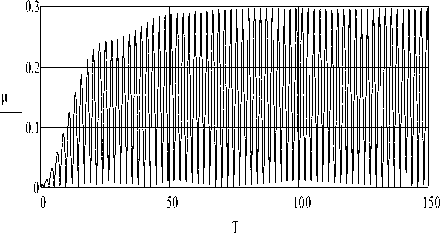
Fig.6. The graph m = m ( T ) of the dry friction coefficient versus time
T ( s )
Fig.7 graphs the dependence m = m ( ^ ) of the dry friction coefficient on the frequency to of the forced oscillations of the damping. It is constructed for the maximum dry friction coefficients m that were determined at each fixed frequency to in the "resonant" interval 1.1 < to < 1.4 from the graphs, one of which is shown in Fig. 6.
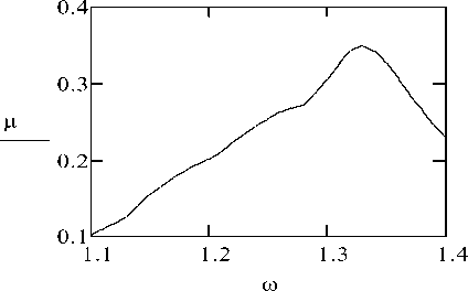
Fig.7. The graph of the dependence m = M ( to ) of the dry friction coefficient on the frequency to of the forced oscillations
We have established the following important fact: when designing a rolling absorber for a friction pair "ball-spherical surface", one should choose such structural materials, the coefficient of dry friction of which has a value not lower than the value defined above.
In this case, the interaction of conventional friction pairs (such as "steel – steel", "concrete – steel" or "concrete – concrete") does not ensure the rolling of the ball without sliding in a spherical cavity. Thus, it is necessary either to use special constructional materials to artificially increase the coefficient of friction between the ball and the spherical surface (as was done in [19 – 21]), or in general to change the design of the absorber in which the role of its working body will be played not by a ball, but by a completely another body [10].
Now, we write the condition under which the ball can be separated from the spherical surface. For this, we equate to zero the projection of the coupling reaction R on the normal n . As a result, we obtain the required condition for detachment in the general form:
R N = 0. (6.8)
Starting from (6.3) and (6.8), it is possible to determine possible cases of ball breaking for such, for example, mutual positions and motions of the ball and
п the carrier body, as: n = ±~ , П = 0, x = 0. In these cases, the ball stops (the condition n = 0) in the two
п extreme positions with the angles n = ±™ of deviation from the vertical OZ , and the carrier body at this instant of time moves without acceleration (condition x = 0).
We give a graph of the functional dependence RN on time T ( s ) (Fig.8), obtained up to constant factors in the numerical integration of the system of non-linear equations (4.13) – (4.14) for the case under study.
RBN
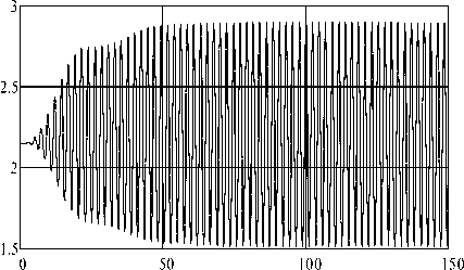
Fig.8. The time evolution of the projection of the reaction R to the normal n
As seen in Fig.8, the periodic curve RN does not intersect the horizontal axis at any point. From this it follows that the movement of the ball in a spherical recess for a given damping system and with the selected power and frequency characteristics takes place without the loss of contact of the ball with the surface of the spherical recess.
VII. Conclusion and Recommendations
In the work, a mathematical model is constructed that describes the forced oscillations of a damping system with a ball vibration absorber. The model analytically considers the effect of the "pure" ball rolling relative to the spherical cavity and the effect of such motion on the dynamic behaviour of the carrier object.
The principal possibility of using the device "ball in a spherical cavity" as a damper for forced oscillations of load-carrier objects is substantiated.
Dynamic behaviour of a damping system with a ball absorber is analyzed depending on the parameters of its setting. It is established that the main parameters of regulation and setting of the absorber are: a) the difference between the radii of a spherical cavity and a heavy ball; b) coefficient of damping of the working body of the absorber; c) the mass ratio of the heavy ball and the carrier object.
Based on the obtained model, a simple numerical-graphical method for determining the optimum values of the setting parameters of a ball absorber is developed.
The effectiveness of the method of vibration protection of large-sized carrier objects with the use of the proposed ball absorber is proved. It is shown that with the optimal adjustment of its parameters, the amplitude of the forced oscillations of the carrier objects can be reduced by a factor of 3.5.
The conditions for physical realization of the pure rolling of the ball in the spherical recess of the absorber are established, as well as the conditions for its rolling without detachments. When designing a ball absorber for a friction pair "ball – spherical recess", it is necessary to choose such structural materials that ensure rolling of the ball in the recess without sliding.
Significant structural drawbacks of ball absorbers of this type are noted:
-
1) they are not isochronous (i.e., they do not retain the required setting frequency) and can be correctly applied only for small relative deviations of the ball from the equilibrium position.
-
2) the frequency of the input action significantly affects the value of the coefficient of dry friction, which is minimally necessary for the physical realization of the “pure” rolling of the ball in a spherical cavity.
In future research, designs of new roller absorbers will be proposed, which are free from the indicated drawbacks.
The results of this research can be used by scientific experts and developers of new absorbers in preparation of their design decisions and in the process of selecting the optimal parameters.
References Mathematical model of the damping process in a one system with a ball vibration absorber
- Dynamic calculation of buildings and structures: Handbook of the designer (in Russian) / Ed. B.G. Korenev, I.M. Rabinovich. – Moscow: Stroiizdat, 1984. – 304 p.
- Dynamic calculation of special engineering buildings and structures: Handbook of the designer (in Russian) / Ed. B.G. Korenev, A.F. Smirnov. – M.: Stroiizdat, 1986. – 185 p.
- Adhikari S., Ali F. Energy Harvesting Dynamic Vibration Absorbers // J. App. Mech., 2013, Vol. 80, P. 1 – 9.
- Chang C.C. Mass dampers and their optimal designs for building vibration control // Eng. Struct. – 1999. – 21. – P. 454 – 463.
- Den Hartog J.P. Mechanical Vibrations. McGraw-Hill, New York, 1956. – 436 p.
- Kärnä T. Damping methods to mitigate wind-induced vibrations // J. Struct. Mech. –2009. – 42, N1. – P. 38 – 47.
- Keutgen R., Lilien J.–L. A new damper to solve galloping on bundled lines. Theoretical background, laboratory and field results // IEEE Transactions on Power Delivery, 1998, Vol.13, №1. – P. 260 – 265.
- Korenev B.G., Reznikov L.M. Dynamic Vibration Absorbers – Theory and Technical Applications. Chichester. “John Willey and Sons”. – 1993. – 296 p.
- Kwok K.C.S. Damping increase in building with tuned mass damper // ASCE J. Eng. Mech. – 1984. – 110, N11. – P. 1645 – 1649.
- Legeza V.P. Numerical analysis of the motion of a ball in an ellipsoidal cavity with a moving upper bearing // Soviet Applied Mechanics. – 1987. – Vol. 23, №2. – P. 191 – 195.
- Legeza V.P. Kinematics and dynamics of a mechanical system on rollers that provide nonholonomic constraints // Journal of Mathematical Sciences (Kluwer Academic Publishers–Plenum Publishers). –1994. – Vol. 72, №5. – P. 3299 – 3305.
- Legeza V.P. Plane problem on a heavy ball rolling in a spherical recess of an inverted pendulum // Int. Appl. Mech. – 2001. – Vol. 37, №8. – P. 1089 – 1093.
- Legeza V.P. Rolling of a Heavy Ball in a Spherical Recess of a Translationally Moving Body // Int. Appl. Mech. – 2002. – Vol. 38, №6. – P. 758 – 764.
- Li J., Zhang Z., Chen J. Experimental Study on Vibration Control of Offshore Wind Turbines Using a Ball Vibration Absorber // J. Energy and Power Engineering, 2012, № 4. – P. 153 – 157.
- Lobas L.G. On Rolling Systems // Int. Appl. Mech. – 2000. – 36, № 5. – P. 691 – 696.
- Lurie A.I. Analytical mechanics. – Berlin: Springer – Verlag, 2002. – 864 p.
- Naprstek J., Fisher C., Pirner M., Fisher O. Non-linear dynamic behavior of a ball vibration absorber // 3rd ECCOMAS Thematic Conference on Computational Methods in Structural Dynamics and Earthquake Engineering (COMPDYN 2011). Corfu, Greece, 26 – 28 May 2011. – P. 1 – 14.
- Neimark Yu.I., Fufayev N.A. Dynamics of nonholonomic systems. – Providence: Amer. Mathem. Society, 2004. – 518 p.
- Pirner M. Actual Behaviour of a Ball Vibration Absorber // Wind Engineering and Industrial Aerodynamics. – 2002, Vol. 90, №8. – P. 987 – 1005.
- Pirner M., Fischer O. One prototype of the ball absorber and its effect on the tower // Int. Association for Shell and Spatial Struct. Proc. Working Group IV Masts and Towers. 19th Meeting in Krakow, Poland, September, 1999. – P. 187–196.
- Pirner M., Fischer O. The development of a ball vibration absorber for the use on towers // IASS, Jour. Of the Int. Association for shell and spatial structures, 2000, Vol. 41, №2. – P. 91 – 99.
- Weaver W., Timoshenko S.P., Young D.H. Vibration Problems in Engineering, 5th Edition. – John Wiley (N.Y.), 1990. – 624 p.
- Zhang Z. –L., Chen J.–B., Li J. Theoretical study and experimental verification of vibration control of offshore wind turbines by a ball vibration absorber // Structure and Infrastructure Engineering, Taylor & Francis, 2014, Vol. 10, № 8. – P. 1087 – 1100.
- Zhang Z. –L., Li J., Nielsen S.R.K., Basu B. Mitigation of edgewise vibrations in wind turbine blades by means of roller dampers // J. of Sound and Vibration, 333 (2014). – P. 5283 – 5298.
- Zhengbing Hu, V.P.Legeza, I.A.Dychka, D.V.Legeza, "Mathematical Modeling of the Process of Vibration Protection in a System with two-mass Damper Pendulum", International Journal of Intelligent Systems and Applications(IJISA), Vol.9, No.3, pp.18-25, 2017. DOI: 10.5815/ijisa.2017.03.03
