Mathematical Modeling of the Process of Vibration Protection in a System with two-mass Damper Pendulum

Author: Zhengbing Hu, V.P.Legeza, I.A.Dychka, D.V.Legeza
Journal: International Journal of Intelligent Systems and Applications(IJISA) @ijisa
Article in issue: 3 vol.9, 2017.
Free access
We analyzed the dynamic behavior of the damping system with a two-mass damper pendulum. The equations of motion of nonlinear systems were built. AFC equation systems have been identified in the linear formulation. Proposed and implemented a new numerical method of determining the optimum parameters of optimal settings two-mass damper.
Damping System, Two-Mass Damper Pendulum, Amplitude-Frequency Characteristic (AFC), Parameters Absorber Settings
Short address: https://sciup.org/15010909
IDR: 15010909
Text of the scientific article Mathematical Modeling of the Process of Vibration Protection in a System with two-mass Damper Pendulum
Published Online March 2017 in MECS
Currently, the decision of problems of vibration control and suppression forced vibrations of flexible high-rise buildings and other extended objects are relevant enough. This is due to two main reasons. On the one hand, abrupt changes in climatic conditions, observed in recent decades, leading to an increase in the average level of wind and sediment loads (snow, ice) on the flexible extended objects. On the other hand, an increase in height (or length) of extended flexible facilities while optimizing load-bearing capacity and to minimize their weight results in a loss of stability of periodic movements and the emergence of various kinds of uncontrolled bifurcations, which are the result of serious accidents at work.
This applies in particular to the high-rise buildings, television towers, radio masts, chimneys [1–11], large-power transmission lines [12–19], carrying trunks of wind power plants, cable-stayed bridges [20–24].
In order to reduce and stabilize the level of the forced oscillation amplitudes in the construction industry, power industry, transport, mechanical engineering and other industries use different dynamic dampers (TMD – tuned mass damper). The principle of operation of such devices is based on the change in the structure of the original mechanical system by introducing an additional so-called mass damper attached. As a result, the system is transformed into a new "carrier (body) - damper" dynamic system. The parameters of the connected (or working), the mass damper is selected in such a way that she made anti-phase oscillations of the object relative to the carrier. Such a movement of the working masses at the optimum damper setting its parameters leads to the suppression of forced oscillations of the carrier object, caused by an external dynamic perturbation. Therefore, reducing the maximum level of the amplitude of the forced oscillations carrying objects in such a case can be considered as effective suppression forced oscillations.
The first who proposed analytical formulas for the optimum adjustment of TMD-absorbers in a linear formulation of the problem, was Den Hartog J.P. [13, 14]. These dampers were used and today are used in the practice of suppressing vibrations of TV towers, metal chimneys and other flexible high-rise buildings [2-4, 8, 10, 11, 25, 26]. In comparison with other passive devices suppression forced oscillations TMD-absorbers can be installed on high-rise buildings without special technical and design problems. Technical details of various designs TMD-absorbers differ on ways to ensure the damping of vibrations of the working body, which they implemented [2, 3, 10, 11]. Methods for determining the optimum parameters of TMD-absorbers adjustment (i.e. the mass of the working of the absorber body, stiffening elements of its accession to the supporting entity and the level of damping vibrations of the working body of the absorber relative to the carrier of the object) in different productions for virtually all kinds of external influences are well established [2 - 5, 6, 10, 11, 27, 28, 32].
It is experimentally proved that the use of TMD-absorbers significantly reduces the amplitude of the forced oscillations [3, 6, 10, 16, 20]. Rating TMD-absorbers partly based on the simplicity of the formulas used for the construction of these devices.
At the end of this quick review the note of [7, 9, 20-22, 25, 26] a number of Czech and Chinese scientists in the study of the dynamic behavior of vibration isolation systems with ball absorber forced oscillations of different nature (BVA–Ball Vibration Absorber). Effect suppression forced oscillations of the carrier object using BVA is rolling a heavy ball at the base of the spherical recess with a constant radius R , lined with a special material with a high coefficient of friction. The ball has a smaller radius r than the radius R of the spherical bearing recess, and represents a working absorber body with a relatively large mass. It is known [5, 9, 26] that the own frequency of the damper depends on the difference betwee n these r adii is determined by the formula од = /--- — ---. However, the design of such dampers
D p,4( R - r )
have a number of technical and dynamic shortcomings, among which we should highlight them nonisochronism, and as a consequence, the impossibility of their use at high amplitudes carrying objects. In addition, constructive setting such absorbers by changing the mass and radius of the ball, and is non-technological in circumstances where this mass of several tons.
This work is a continuation of research work [5, 28 – 30], carried out in the framework of the studies the dynamic behavior of vibration isolation systems with dampers of various designs. It is considered a passive method of suppression of forced oscillations of extended flexible structures using a new pendulum absorber with two attached masses. Proposed in the pendulum absorber also can be classified as TMD – absorbers mentioned above.
In addition, an important feature of these dampers is their compactness, reliability and ease of tuning (Fig. 1 and Fig.2).
-
II. Statement of the Problem
We consider the periodic motion damping system of rigid bodies "supporting body – the two–mass damper forced oscillations" by an external harmonic action F ( t ) = F 0sin( ro t ) . Fig.1 shows a general view of the considered damping system for modeling the dynamics of which takes into account the vertical movement of the absorber with the highest point of the altitude of the object with its deviation from the vertical.
However, in this study accepted for consideration by the working circuit (Fig.2) modeling the dynamics of damping system with a two-mass damper, wherein said vertical displacement is not taken into account. This is because, according to regulatory documents [4, 10], in real systems, extended horizontal deviation of the top of the buildings must not exceed 1% of its height. Therefore, the vertical movement should not exceed 1% of the horizontal deflection top of high–rise buildings. For real structures 100 in height – the vertical movement of the upper points of 300 meters is 1 – 3 cm, which can be neglected.
The supporting body in Fig. 2 simulates flexible structure or an extended object, and has a reduced mass M . This is in a flexible extended object considered by the first (main) form with the natural frequency ro 0 .
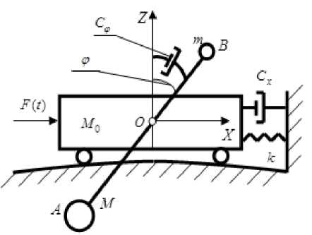
Fig.1. General view of the damping system with a two-mass absorber

Fig.2. Working scheme simulation damping system with a two-mass absorber
Two-mass dampener pendulum is a rigid weightless rod, at the opposite ends of which are mounted (with the possibility of free movement), two unequal lumped mass. This large mass M is fixed to the lower end of the damper and less weight m - at the upper end ( M > m ). This kind of two–mass pendulum AB pivotally mounted on the carrier body weight M at the point O . Shoulder length AO is equal L to the bottom of the pendulum, and the length of the upper part BO of the shoulder – l . It is assumed that the shoulders AO and BO absolutely rigid and weightless. Setting the pendulum is done simply by changing the masses M and m , as well as the lengths L and l . The friction in the joint O is not taken into account.
The absorption of the energy absorber is carried out by the forces of viscous resistance in the damper with viscous drag coefficient C .
The movement of the carrier body is seen along the axis OX of this movement and prevents the elastic element with stiffness coefficient k and viscous damper with viscous drag coefficient C . Last introduced to take account of the damping due to internal friction forces in the materials of construction or extended vertical shaft of the flexible object.
Purpose of paper – to create a mathematical model of the dynamic behavior of the studied damping system and analytical determination of the equation of its AFC in the linear formulation.
-
III. The Equations of Motion Damping System. Determination of the own Frequency of two-mass Pendulum Damper
Formulate geometric relationships for the centers of masses M and m (Fig. 2). We choose as the independent generalized coordinates of the system following options: ф - deflection rod damper angle from the vertical axis OZ , and x 0 – moving the center of mass M 0 (CM) of the supporting body along the axis OX .
To have a center of mass M :
Xm = Xo - L sin ф(1)
Zm — - L cosф(2)
To have a center of mass m :
xm — x0 +1 sin ф(3)
Zm = 1 COSф
In the construction of the differential equations of motion of damping system using Lagrange formalism [31]. We write the expression for the kinetic energy of the system:
T _ ^о x 0 + m [( x 0 + 1 CoS ф . ф )2 + 1 2sin2 ф* ф +
+ M[(x0 -Lcosф•ф)2 + L2sin2 ф*ф2](5)
After some transformations we obtain:
Mx2 m 2 22
T — ——+ — [ X o + 2 X o 1 cos ф* ф + 1 ф ] +
M
— [x0 - 2x0L cos ф * ф + L ф ](6)
We form the expression for the sum of the elementary works on the corresponding virtual movements of the masses of the mechanical system in the independent generalized coordinates:
5 A — [ F(t ) - ( kx0 + Cx0 )] 5 x 0 - MLg sin ф5ф +
+ mg1 sin ф5ф - С фф * 5ф (7)
The equation of the second kind Lagrange in the general form:
d I d T \ dT _ . ~
—I— I--— Qi, i — 1, n dt ^ dqi J dqi
We find the generalized forces Qi - the right of the Lagrange equations. For this purpose, we rewrite equation (7) in the general form:
SA — Qx5x0 + Qф5ф(9)
Comparing the expressions (7) and (9), define the generalized forces Qi :
Qx — F (t) - (kx0 + CxX0)
Оф — (m1 - ML)g sin ф - Сфф(11)
Substituting the expression (6), (10), (11) in the formula (8). As a result, we obtain the differential equations of motion of damping system:
( M o + M + m ) x 0 + Cx 0 + kx 0 +
(ML - m1 )(ф2 sin ф - ф cos ф) — F sin(^t) ,(12)
( ML 2 + m1 2 ) ф + Сф ф - ( ML - m1 ) x 0 cos ф +
+g(ML - m1) sin ф — 0(13)
After some transformations we can write the final system of equations:
(1 + V + A )) x 0 + 2 nx x 0 + ^ ) X 0 +
+p(ф sin ф - ф cos ф) — F0 sin(^t) ,(14)
x0 cos ф — qф + 2пфф + g sin ф,(15)
Mm where v —--- ; a — ;
M0
F — ;
0 M 0
2 n — C^ ;
x M 0
^ n —-- ; A — ML - m1 ;
0 M 0
p — F ; E — ML + m1 2 ;
M 0
E q— д;2 пф
— . We assume that A > 0. A
If you do not take into account the damping in the two-mass damper (Сф — 0) and consider supporting body as a still (x0 (t) = 0), then the system of equations (14) - (15) is converted into a single differential equation of motion of a pendulum with a fixed point O of suspension relative to the fixed bearing body. This equation has the form:
g ф +— sin ф = 0.
q
From equation (16) define the frequency of small natural oscillations of two-mass damper:
I ML - ml ML 2 + ml 2 g '
From (17) it follows that the frequency of small natural oscillations of the two-mass pendulum absorber is frequency of small natural oscillations of a mathematical pendulum with an equivalent length of suspension:
_ ML + ml 2 L 2 + Дг
E = ML - ml ~ L - p l ’
m where и = — . M
As expected, when m = 0 the formula (17) becomes the well-known formula for the frequency of small natural oscillations of mathematical pendulum on the suspension length L = LE :
" B =
From (17) it also follows that the correct functioning of the damper can only be provided: ML - ml > 0 . This formula thus establishes that the regulation of the frequency of natural oscillations of two-mass pendulum absorber is possible by changing the three main damper settings (as opposed, for example, absorbers of other structures): l , L , д . It provides a broader and more flexible customization options absorbers such an arrangement to the desired natural frequency of the supporting body, as well as significantly expand the range of operating frequencies (0,2 to 12 rad / s ) of two-mass dampers while maintaining their compactness.
-
IV. Determining the AFC of a Dynamic System in Linear Formulation of the Problem
We consider small steady-state oscillations of the studied system. This is explained by the fact that, in accordance with the regulations [4, 10], the maximum deviation of the top of high-rise buildings from the vertical must not exceed 1% of its height. The above regulatory limit also entails appropriate restrictions on the value of the maximum angular deviations two-mass damper pendulum from the vertical. Marked limitation for single-mass pendulum absorbers are determined in such a range of angles ф < 0,10 (angle ф measured in radians). We will also be guided by this inequality.
In addition, the study of the problem in the linear formulation of independent interest, since it provides an opportunity to identify the main features of dynamic performance and dynamic behavior of the considered damping systems are already known methods.
Given the smallness of the parameter ф , we linearize the system equations (1) - (2):
(1 + v + д 0 ) x0 + 2 nxx0 + " 2 x 0 - р ф = F 0 sin( " t ) , (19)
x 0 = q ф+ 2 п фф + д ф • (20)
To derive the equations AFC investigated damping system of any of the known approaches can be used in the linear formulation [4, 14, 32].
Omitting the intermediate transformations, we write the final expressions for the amplitude A ( " ) of the carrier body and angle B ( " ) of deviation from the vertical a working body of absorber:
A ( " ) = n F0
ф 2 ( " ) +ф 2 ( " )
B(")= , F0V®0" , ф2 (")+ф 2 (")
where
"
( 2 П ф " ) + ( q " 2 - g )
ф 1 ( " ) = 2 nx ro + 2 П ф p "® 0 ( " ) ;
ф 2 ( " ) = [ " ) - ( 1 + v + Д 0 ) " 2 ] + P ( q " 2 - g ) ф 0 ( " ) •
-
V. Numerical Analysis
Qualitative and quantitative analysis of the received frequency response (21) damping system was carried out on the basis of numerical methods. The main task of the numerical experiment was to determine these frequency parameters m, M, l, L of a two-mass pendulum absorber, in which the frequency response graph system would have a symmetrical shape with equal values of maximum amplitudes at two frequencies "1 and "2 , one of which corresponds to the supporting body, and the other -dampers [5, 11, 14, 20, 30]. Physically, this means that the energy of forced oscillations for each cycle is divided equally between the supporting body and an absorber, which leads to a decrease in the amplitude of the level of forced oscillations of the carrier body. The optimal parameters of the proposed absorber were installed using numerical-graphical method described in studies of the dynamics of roller dampers (BVA) [5, 30].
The next step after the establishment of such a symmetrical shape is carried out to minimize the frequency response magnitude of the amplitude of the carrier body by choosing the optimal value п ф [5, 30]. If the two-mass system frequency response graphs are asymmetric shape, this means that the settings are not optimal absorber selected.
For the numerical experiments on frequency ^ = 1,5 рад I с were chosen following parameters absorber: L = 2 м ; l = 1,5 м ; v = 0,05; ц 0 = 0,03; пф = 0,45 м I с . Additionally, parameters the supporting body have been chosen nx = 0,03 с 1 and F o = 0,003 g in accordance with the regulatory requirements [4, 10].
Fig.3 shows a graph for the frequency response of the carrier body consisting damping system with the above parameters. The maximum amplitude of the carrier body in this case is A = 0,122 m .
п ф = 0,45 m I s , which is equal to A = 0,122 m .
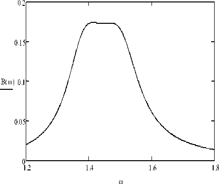
Fig.4. Frequency response B ( ® ) for the angular deviation (in radians) from the vertical axis of the absorber for the system with the same parameters.
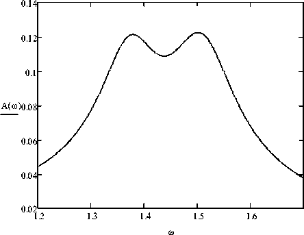
Fig.3. Frequency response A ( ® ) (in meters), built for the damping system with the following parameters: ^ = 1,5 rad I У ; L = 2 m ;
l = 1,5 m ; v = 0,05 ; ц 0 = 0,03 ; п ф = 0,45 m I s ; n x = 0,03 s - 1 ; F = 0,003 g
Fig. 4 shows a graph of the frequency response of the absorber axis angular deviation from vertical (in radians). Its characteristic feature is that part of it which has a horizontal platform with a maximum deviation from the vertical axis of the damper. This feature also indicates the optimality of the absorber tuning parameters.
The marked numerical experiment, the problem of determining the optimum value of the coefficient n is of independent interest. Fig. 5 shows how the maximum amplitude A of the carrier body, depending on the change in value of the coefficient п ф for fixed values of the remaining parameters.
The graph shows an interesting fact – the function A = A ( п ф ) has a pronounced local minimum at the point
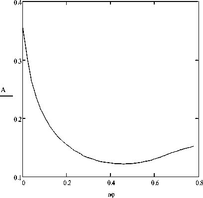
Fig.5. Schedule of the maximum amplitude A = A ( П ф ) (in meters)
carrying body depending on the value of the coefficient n for the system with the same parameters.
This behavior A = A ( п ф ) makes it possible to function with an appropriate change in the coefficient п ф to determine the minimum value of the amplitude of the forced oscillations for a given set of parameters specific damping system.
The graph in Fig.5 also reflects the following feature of the studied system: a gradual increase in the ratio leads to an increase in the amplitude of the forced oscillations of the supporting body after reaching its minimum value it. Previously, the existence of a local minimum, but in a system with dry friction, was marked by one of the authors in [5]. Physically, it means that the absorber meets the ever-increasing resistance of the viscous with two-mass Damper Pendulum damper and high values of the coefficient is practically held him without producing relative oscillation movements (i.e. absorber "overdamped"). In this case, the two-mass damper pendulum does not work properly, and its two working masses and only create additional dynamic impact on the carrying shaft of the protected object.
For comparison, Fig.6 shows a plot of the frequency response A ( to ) of the mechanical system without an absorber. In this case, the maximum amplitude of the carrier body equal to the value A max = 0,312 m and attained at a frequency to max = 1,5 rad / s . This maximum amplitude is approximately 2.56 times higher than when using the absorber A = 0,122 m .
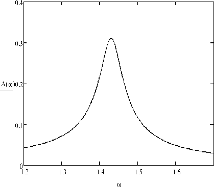
Fig.6. Schedule AFC (in meters) of the studied mechanical system without damper
-
VI. Conclusions
The paper presents the dynamic equations of motion for a new damping system "supporting body – the two-mass damper pendulum". On the basis of the equations of motion are derived and analyzed the frequency response of the equation in the linear formulation. The proposed method of determining the AFC of the equation to optimize the selection of regulatory parameters when setting up a two-mass pendulum absorber on the desired mode of vibration protection of flexible elongated objects. The main criterion of such a regime – line maximum values of the amplitudes of the carrier body the requirements of existing regulations. Numerical experiment conducted on the basis of the AFC of the equation obtained in this study showed that the proposed damping system forced oscillations is effective. This system allows several times to reduce the amplitude of forced oscillations of the carrying bodies. This effect is achieved due to special setting damper settings on the corresponding frequency of own oscillations of the carrier body.
For this two-mass damper tuning frequency should be performed using the optimal choice of its four main parameters: m, M, l, L . Their selection should be implemented in such a way that the frequency response graph damping system would have a symmetrical shape with equal values of maximum amplitudes and two frequencies, one of which corresponds to the supporting body, and the other – absorbers. Physically, this means that the energy of forced oscillations for each full cycle is divided equally between the supporting body and an absorber, which can significantly reduce the level of amplitude of forced oscillations of the carrier body.
The paper also highlighted another interesting feature of the system under study: the function A = A ( п ф ) has a pronounced local minimum, which enables you to set the level of the damper viscous damping forced vibrations.
Results of the study process, the system of vibration protection in the linear formulation allow a sufficient degree of accuracy to estimate and predict its basic dynamic performance.
Development of the method for determining the frequency response damping system and optimal settings for dual-mass damper problem in nonlinear statement is a separate urgent problem to be posed and solved in future studies.
Results of the study may be of interest of experts in the field of dynamics and strength of machines and mechanisms, theoretical mechanics, vibration protection of high-rise buildings and power lines, as well as recommended for developers and designers of new dampers.
References Mathematical Modeling of the Process of Vibration Protection in a System with two-mass Damper Pendulum
- Chang C.C. Mass dampers and their optimal designs for building vibration control // Eng. Struct. – 1999. – 21. – P. 454 – 463 .
- Kärnä T.Damping methods to mitigate wind-induced vibrations // J. Struct. Mech. – 2009. – 42, N1. – P. 38 – 47.
- Kwok K.C.S. Damping increase in building with tuned mass damper // ASCE J. Eng. Mech. – 1984. – 110, N11. – P. 1645 – 1649.
- Korenev B.G., Reznikov L.M. Dynamic Vibration Absorbers – Theory and Technical Applications. Chichester. "John Willey and Sons". – 1993. – 296 p.
- Legeza V.P. The theory of vibration protection systems using isochronous roller dampers (models, methods, dynamic analysis, technical solutions) (in Russian). – Saarbrücken (Deutschland): LAMBERT Academic Publishing, 2013. – 116 p.
- Mead D.J. Passive vibration control. – New York: J. Wiley & Sons, 1999. – 540 p.
- Naprstek J., Fisher C., Pirner M., Fisher O. Non-linear dynamic behavior of a ball vibration absorber // 3rd ECCOMAS Thematic Conference on Computational Methods in Structural Dynamics and Earthquake Engineering (COMPDYN 2011). Corfu, Greece, 26 – 28 May 2011. – P. 1 – 14.
- Ogawa K., Sakai F., Hayashi K. Development of impact mass damper and its applications to tower structure // Kawasaki Technical Review. – 1991. – N108. – P. 84 – 89.
- Pirner M. Actual Behaviour of a Ball Vibration Absorber // Wind Engineering and Industrial Aerodynamics, 2002, Vol. 90, №8. – P. 987 – 1005.
- Simiu E., Scanlan R.H. Wind effects on structures: Fundamentals and applications to design, 3th Edition. – John Wiley (N.Y.), 1996. – 688 p.
- Snowdon J. C. Vibration and shock in damped mechanical systems. – John Wiley (N.Y.), 1968. – 473 p.
- Danilin A.N., Shklarchuk F.N., Lilien J.-L., Snegovski D.V., Vinogradov A.A., Djamanbayev M.A. Nonlinear Aeroelastic Vibrations and Galloping of Iced Conductor Lines under Wind // 7th Intern. Symp. On Cable Dynamics. Vienna (Austria), 10–13 Decemder 2007. – P. 129 – 134.
- Den Hartog J.P. Transmission line's vibrations due to sleet // Transactions AIEE. 1932. V.51. – P.1074 – 1076.
- Den Hartog J.P. Mechanical Vibrations. McGraw-Hill, New York, 1956. –436 p.
- EPRI Transmission line reference book. Wind-induced Conductor motion. Electric Power Research Institute: Final Report, November, 2006.
- Keutgen R., Lilien J.-L. A new damper to solve galloping on bundled lines. Theoretical background, laboratory and field results // IEEE Transactions on Power Delivery, 1998, Vol.13, №1. – P. 260– 265.
- Lilien J.-L., Snegovski D. Hurricane Simulation on Power Transmission Line // Proc. Vth Cable Dynamics Symp., Santa Margherita. 2003. – P. 313 – 318.
- Lilien J.-L., Snegovski D. Wake–Induced Vibration of Power Transmission Line: Parametric Study // Proc. 8th Conf. on Flow-Induced, Paris, 2004. – P. 421 – 425.
- State of the art of conductor galloping. CIGRE Technical Brochure 322. Task force B2.11.06. Convenor Lilien J.-L. June 2007. – 140 p.
- Li J., Zhang Z., Chen J. Experimental Study on Vibration Control of Offshore Wind Turbines Using a Ball Vibration Absorber // J. Energy and Power Engineering, 2012, № 4. – P. 153 – 157.
- Zhang Z.-L., Chen J.-B., Li J. Theoretical study and experimental verification of vibration control of offshore wind turbines by a ball vibration absorber // Structure and Infrastructure Engineering, Taylor & Francis, 2014, Vol. 10, № 8. – P. 1087 – 1100.
- Zhang Z.-L., Li J., Nielsen S.R.K., Basu B. Mitigation of edgewise vibrations in wind turbine blades by means of roller dampers // J. of Sound and Vibration, 2014, Vol. 333, Vol. 21. – P. 5283 – 5298.
- Achkire Y., Bossens F., Preumont A. Active damping and flutter control of cable-stayed bridges // J. of Wind Engineering and Industrial Aerodynamics. – 1998, Vol. 74–76. – P. 913–921.
- Lilien J.-L., Da Costa A.P. Vibration amplitudes caused by parametric excitation of cable stayed structures // Journal of Sound and Vibration, 1994, Vol. 174, №1. – P. 69 – 90.
- Pirner M., Fischer O. One prototype of the ball absorber and its effect on the tower // Int. Association for Shell and Spatial Struct. Proc. Working Group IV Masts and Towers. 19th Meeting in Krakow, Poland, September, 1999. – P. 187–196.
- Pirner M., Fischer O. The development of a ball vibration absorber for the use on towers // IASS, Jour. Of the Int. Association for shell and spatial structures, 2000, Vol. 41, №2. – P. 91 – 99.
- Abe M., Fujino Y. Dynamic characterization of multiple tuned mass and same design formulas // Int. J. Earthquake Eng. and Struct. Dyn. – 1994. – 23. – P. 813 – 835.
- Fujino Y., Abe M. Design formulas for tuned mass damper based on a perturbation technique // Int. J. Earthquake Eng. and Struct. Dyn. – 1993. – 22. – P. 833 – 854.
- Legeza V.P. Cycloidal Pendulum with a Rolling Cylinder // Mechanics of Solids. – 2012, Vol. 47, №4. – P. 380 – 384.
- Legeza V.P. Brachistochrone for a rolling cylinder // Mechanics of Solids. – 2010. Vol. 45, №1. – P. 27 – 33.
- Legeza V.P. Efficiency of a Vibroprotection System with an Isochronous Roller Damper // Mechanics of Solids, 2013. Vol. 48, №2. – P. 168 – 177.
- Weaver W., Timoshenko S.P., Young D.H. Vibration Problems in Engineering, 5th Edition. – John Wiley (N.Y.), 1990. – 624 p.
- Xu Y.L., Kwok K.C.S. Semianalytical method for parametric study of tuned mass damper // ASCE J. Struct. Eng. – 1994. – 120, N3. – P. 747 – 764.
