Mechatronics Design of a Mobile Robot System

Author: Ahmad A. Mahfouz, Ayman A. Aly, Farhan A. Salem
Journal: International Journal of Intelligent Systems and Applications(IJISA) @ijisa
Article in issue: 3 vol.5, 2013.
Free access
Mobile robot motion control is simplified to a DC motor motion control that may include gear system. The simplest and widespread approach to control the mobile robot motion is the differential drive style, it consists of two in-lines with each a DC motor. Both DC motors are independently powered so the desired movements will rely on how these two DC motors are commanded. Thedevelop design, model and control of Mechatronics mobile robotic system is presented in this paper. The developed robotic system is intended for research purposes as well as for educational process. The model of proposed mobile robot was created and verified using MATLAB-Simulink software.
Wheeled Mobile Robot, PMDC Motor, Mathematical Model
Short address: https://sciup.org/15010383
IDR: 15010383
Text of the scientific article Mechatronics Design of a Mobile Robot System
Published Online February 2013 in MECS
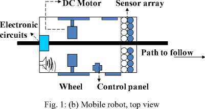
The mobile robot system takes input voltage as actuator input, and outputs the rotational speed of the two wheels, the actuator most used for mobile robot is DC motor, because their torque-speed characteristics are achievable with different electrical configurations and their speeds can be smoothly controlled and in most cases are reversible. DC Motor control system design and its features can be analyzed by MATLAB software. Using a simple controller of PIC microcontroller, the rotation of PM motors or the Motion of Robot can be controlled easily [1].
One application form of mobile robot is line follower wheelchair, to help and support people with disabilities and special needs to perform specific predetermined tasks e.g. religious rituals (motion around holy Kaba,
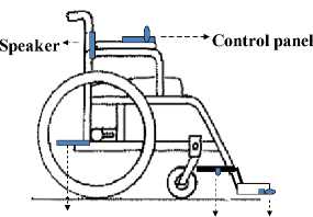
Electronic circuit Sensors array Ultrasonic sensor
Fig. 1: (a) Mobile robot, side view
-
II. Modeling of the Mobile Robot
The mobile robot motion control is simplified to a PMDC motor motion control. The PMDC motor is an example of electromechanical systems with electrical and mechanical components, a simplified equivalent representation of PMDC motor's twocomponents are shown in Fig.2 (b).The equations of motion for the robot will consider the simple case of single-degree-of freedom motion of the robot, moving forward and reverse. A simplified model of a symmetric half of the robot is constructed as shown in Fig. 2(a) and used to write the equivalent model.
Plant, (Robot)
-
Fig. 2: (a) A simple model of half of the robot
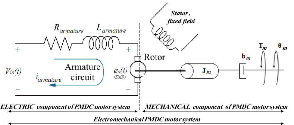
Fig. 2: (b) Schematic of a simplified equivalent representation of the PMDC motor's electromechanical components
Applying a voltage to motor coils, produces a torque in the armature. The torque developed by the motor , T m ,is related to the armature current, i a , by a torque constant K t , and given by the following equation:
Motor Torque = T m = K t * i a (1)
The back electromotive force, EMF voltage, e a is induced by the rotation of the armature windings in the fixed magnetic. The EMF is related to the motor shaft angularspeed, ω m , by a linear relation given by:
Based on the Newton’s law combined with the Kirchoff’s law, the differential equations describing electric characteristics of PMDC motor can be derived; Applying Kirchoff’s law around the electrical loop by summing voltages throughout the R-L circuit gives:
∑ V = V in —V R —V L — EMF =0 (3)
Applying Ohm's law, substituting, rearranging and taking Laplace transform, we get equation that describes the electrical characteristics of DC motor:
e a (t ) = K b
d0 (0
m
= K b ® m dt
V in = R a • i . (t ) + L a ( ^d 1 + K b V dt ;
d 0 (t ) dt
к -T - т
K t i T Load J m
' d 20'
V dt 2 ,

(L a s +R a ) I(s) = V in (s) - K b sθ(s) (4)
The torque, developed by motor, produces an angular velocity, ω= dθ/dt, according to the inertia J and damping friction, b , of the motor and load . Performing the energy balance on the DC motor system; the sum of the torques must equal zero, we have:
∑T = J *α = J*d2θ/dt2
T e – T α – T ω - T EMF = 0
Substituting the following values: Te =K t *i a , T α = J m *d2θ/dt2 , and T ω = b m *dθ/dt , in open loop PMDC motor system without load attached, where the change in T motor is zero gives :
Taking Laplace transform and rearranging, gives:
K t *I(s) - J m *s2θ(s)– b m *s θ(s) = 0
K t I (s)= (J m s + b m ) s θ(s) (5)
The electrical and mechanical PMDC motor two components are coupled to each other through an algebraic torque equation given by (1). To derive the PMDC motor transfer function, we need to rearrange (4) describing electrical characteristics of PMDC, such that we have only I(s) on the right side, then substitute this value of I(s) in (5) describing PMDC mechanical characteristics, this gives:
K t
( L . s + R . )
[ V in ( s ) - Kb « ( s ) ] = J m s 2 0 (ss ) + b m s 0 ( s )
Rearranging (6), we obtain the PMDC motor open loop transfer function without any load attached relating the input voltage, Vin(s), to the angular velocity, ω(s), given by:
G speed ( s ) ,
Vin ( s )
K t
{ [ ( L . s + R . )( J „ s + b „ ) + K t K b ] }
G (ss ) — ^ ( s i — --------------- K----------------
'peed V in ( s ) [ ( L . J , ) s 2 + ( R . J , + b „ L , ) s + ( R . b „ + K t K b ) ]
The total equivalent inertia, Jequiv and total equivalent The equivalent mobile robot system transfer function damping, bequiv at the armature of the motor are given by: will be given by:
|
^ |
2 |
|
|
becfiiV bm + bLoad |
1 V N 2 J |
|
|
( N. |
^ 2 |
|
|
J ecjuiv J m + J Load |
1 V N 2 J |
|
G ^robot (s ) =___________________________Kt / n___________________________ speed Vin (s) [(L,J„„,)s2 + (RaJequv + b',„La)s + (R,b',„ + KtKb)]
For high accuracy , the inertias of the gears and wheels have to be included in the calculations, this value can be obtained from literature or calculated using the equations for the inertia of a cylinder since the gear has a form of cylinder, this can be rewritten as follows:
J — J . + J + ( J , , + mr 2)
equiv motor gear wheel
N 1
N 2 J
The geometry of the part determines the moment of inertia, for simplicity, the mobile robot can be
considered to be of the below shape, with the inertia calculated as shown below, where:
J load
bh 3

The following nominal values for the various parameters of a PMDC motor used : Vin=12 v; Motor torque constant, Kt = 1.188 Nm/A; Armature Resistance, Ra = 0.156Ω ; Armature Inductance, La = 0.82 MH ;Geared-Motor Inertia: Jm = 0.271 kg.m2, Geared-Motor Viscous damping bm = 0.271 N.m.s; Motor back EMF constant, Kb = 1.185 rad/s/V, gear ratio, n=3, wheel radius r =0.075 m, wheelchair height,h= 0.920 m, wheelchair width,b = 0.580 m, the distance between wheels centers = 0.4 m, The total equivalent inertia, Jequivand total equivalent damping, bequivat the armature of the motor are ,Jequiv =0.275 kg.m2 , bequiv = 0.392 N.m.s. The most suitable linear output speed of suggested mobile robot is to move with 0.5 meter per second, (that is ω=V/r = 0.5/ 0.075 = 6.667 rad/s. Tachometerconstant, Ktac = 12 / 6.667=1.8 rad/s.
Substituting values, we obtain the overall mobile robot open loop system transfer function, relating input voltage V in and robot output angular speed ω robot , to be:
= « robot ( s ) , 0.3961
VtnS s ) 0.2256 s 2 + 0.3645 s + 1.469
2.1 State space representation of PMDC open loop system:
The state variables (along with the input functions) used in equations describing the dynamics of a system, provide the future state of the system. Mathematically, the state of the system is described by a set of first-order differential equation in terms of state variables . The state space model takes the following form [1]:
‘ d 9
1 = =
1dt
-_ d 29 _ d to_ Kt * ia bm * to
—--- —-- —-----
-
2 dt 2 dt J JJ
mmm di„ R„ * i„ K, * rn V.
a a a bin
—--—------
-
3 dt La La
dx
= Ax + Bu dt y — CX + Du
Substituting state variables, for electric and mechanical part equations rearranging gives:
Rearranging (4) and (5) to have the below two first order equations, relating the angular speed and armature current:
d 9
— — — x dt
d to_ Kt * ia bm * ro
-- —----- dt J JJ mmm di" R, * i Kh *« V.
a a a bin
-- —------ dt La La
|
x —- b^x 2 J 2 m |
+ K^x J 3 m |
- T l |
|
' K x. —-- -x^ 3 L 2 a |
R a x L a 3 |
+ ± V in La |
Looking at the DC motor position θ , as being the output, and choosing the state variable position θ m , velocity ωm and armature currents ia :
x^ — 9
x^ —
d 9 dt
Looking at DC motor speed, as being the output, the following state space model obtained:
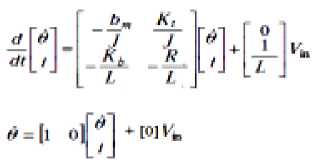
x 3 = i a
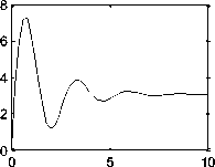
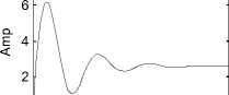
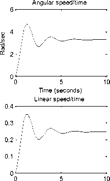
Running the Simulink model of the open loop mobile robot system(see Fig 6(a)), will result in speed/time, linear speed/time, torque/time, and current/time response curves shown in Fig. 4(a),root locus and bode plot are shown Fig. 4(b), as will as running the next m-code:
>>clc, clear all, close all
Vin=12 ; Kt = 1.1882 ; Ra = 0.1557; La = 0.82; Jm = 0.271; bm=0.271;
Kb = 1.185; Kt = 1.1882; n=3;Jm =0.271 ; bm=0.271;
r=0.075;chair_height=0.920;chair_wedth=0.580;
Dist_wheels=0.40;%m, distance between wheels
JLoad =(chair_wedth* (chair_height)^3)/12;
bLoad = 1.091 ;
Jequiv = Jm+ JLoad/(n)^2;
bequiv = bm + bLoad/(3)^2;
desired_linear_speed=0.5;% m/s desired_angular_speed= (desired_linear_speed)/r;
Ktach =Vin/ desired_angular_speed ;
num=[Kt/n];
den=[La*Jequiv(Ra*Jequiv+bequiv*La)
(Ra*bequiv+Kt*Kb)];
G_robot_open= tf(num,den )
step(12*G_robot_open)
sisotool(G_robot_open)
Torque/time
Time (seconds) Current/time
0 5 10
Time (seconds)
Time (seconds)
Fig. 4: (a) open loop mobile robot system; speed/time, torque/time, speed/time and current/time response curves for 12 V input
-
2.2 Robot differential drive Model
The simplest and widespread used approach to control the motion of mobile robot is differential drive style. It consists of two in-lines with each other DC motors. Both DC motors are independently powered so the desired movements will rely on how these wheels are commanded. The overage mobile robot speeds, linear and angular, be calculated at follows:
_ V right _ wheel + V Left _ wheel V r + V l
VRobot = ~ ю =Vr-Vl _ Vr-Vl
Robot The distance between wheels
The linear velocity is the product of the rotational velocity and the signed distance from the instantaneous center of curvature to the midpoint between the two front wheels, ( v = ro*r ), The turning radius, r, of mobile robot can be obtained by dividing (20) by (21), that gives :
V r +V l
= VRobot = 2 = S VR +VL toRobot VR —VL 2 Vr -Vl
S (16)
on these equations, the extracted from [3]
r Turning
Based
Simulink model is modified to be used to demonstrate differential style (see Fig.7), plot robot DC motors speeds, the position of the robot in function of its angle through time, plotting and tracking the central point of the robot, we can feed any function as an input and observe robot motion. Defining PMDC parameters and applying the same inputs to both motors in this model will result in straight line motion; applying different inputs will result in corresponding trajectory (Fig. 5(a), (b), (c)).
Root Locus Editor for Open Loop 1 (OL1) Open-Loop Bode Editor for Open Loop 1 (OL1)
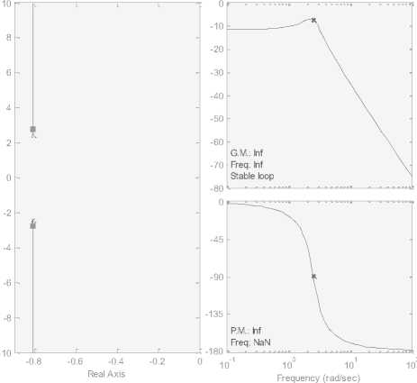
Fig. 4: (b) Root locus and bode plots
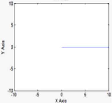
(a)
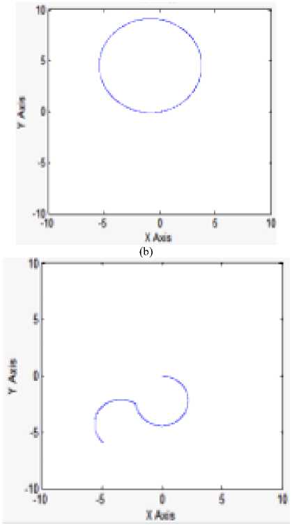
(c)
Fig. 5: (a), (b), (c) Three different trajectories of the central point of the mobile robot
-
III. Controller Design
-
3.1 PID controller design
The term control system design refers to the process of selecting feedback gains that meet design specifications in a closed-loop control system. Most design methods are iterative, combining parameter selection with analysis, simulation, and insight into the dynamics of the plant [4]. A suitable controller for wheeled mobile could be PID controller and Proportional-Integral (PI) controller with deadbeat response.
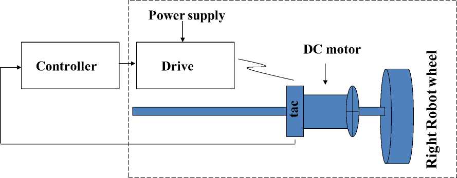
Tachometer is a sensor used to measure the actual output mobile robot angular speed, ro L . . Dynamics of tachometer can be represented using the following equation:
V out (t) =K tac *d 9(t)/dt = V out (t) =K tac * Ю
The transfer function of the tachometer is given by:
V out (s) / ГО($) =K tac
Tachometerconstant, Ktac = 12 / 6.6667=1.8 .
PID controllers are commonly used to regulate the time-domain behavior of many different types of dynamic plants [9]. The gains are to be tuned experimentally to obtain the desired overall desired response. The PID controller transfer function is given by:
c K^ - K d S 2 + K p S + K i
G PID = K P + + K D = ss
K D
KK
2 + —- s + —L KDKD
s
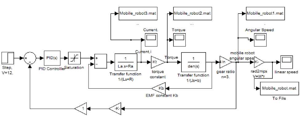
The sign of the controller’s output, will determine the direction in which the motor will turn. The Simulink model of the closed loop mobile robot system with tachometer ,PID controller with gains (KP=36.55, KI =8.33, KD=8.73) is shown in Fig 6(a), running this model will result in response curves shown in Fig 6(b), Several observations can be made from the mobile robot closed loop system with tachometer, first, for 12 V input, the mobile robot will reach output angular speed of 6.67 rad/sin 1,2 s, that is 0.5 m per second. Second, the mobile robot system draws about 17.8 A peak and about 6 A continuous in operation according to this model.
Arm angle feedback, Ktac
Fig. 6: (a), Mobile robot Simulink model with PID controller, closed loop mobile robot with tachometer
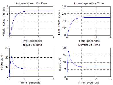
Fig. 6: (b) speed/time, torque/time, speed/time and current/time response curves of the close loop mobile robot system with tachometer feedback and PID controller
Robot differential drive Simulink Model, can be further modified to include PID controller and feedback, to have the form shown in Fig. 7.
-
3.1.1 Suggested Function Block with its Function Block Parameters Window
-
3.1.2 Proportional -Integral (PI) controller with deadbeat response design
a suggested function block model for mobile robot design and analysis using PID controller is shown in Fig.8, by defining parameters and values of each DC motor, controller , gear ratio and controller gains, running model, will result in torque/time, speed/time and position/time curves shown in Fig 6(b) up.
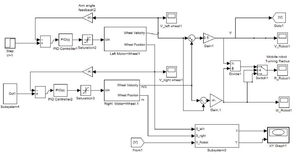
Fig. 7: Robot differential drives Model with PID controller and feedback
Deadbeat response means the response that proceeds rapidly to the desired level and holds at that level with minimal overshoot, [5]. The characteristics of deadbeat response include; Zero steady state error, Fast response, (short rise time and settling time) and minimal undershoot, ±2% error band. PI-controller transfer function is given by:
К, (— Ps + K,)
Gpi (s) = Kp + -I- '-----— = ss
K P

V KP 7
-P (s + Zo)
s
PI controller represents a pole located at the origin and a stable zero placed near the pole, at Zo=- KI/ KP , resulting indrastically eliminating steady state error due to the fact that the feedback control system type is increased by one. The PI pole and zero will affect the response, mainly the PI zero, Z o =- K I / K P , will inversely affect the response and should be cancelled by prefilter,
therefore the required prefilter transfer function to cancel the zero is given by:
G Pr efilter ( s )
Z o
(S + Zo )
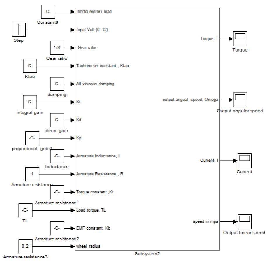
Fig. 8: Function Block using PID controller
The closed loop overall transfer function of the mobile robot Tmobile(s), with PI controller added, can be calculated as follows; The forward transfer function is consisting of PI controller, mobile robot forward loop transfer function, and given by:
G л f (S ) = speed _ forward
« robot ( s )
V in ( s )
Kp (s + Zo)"
K / n
s
r . ) s 2 + ( R J . + b . L ) s + ( Rb .
equiv a equiv equiv a a equiv
|
G « robot ( s ) = |
( s + Z o ) K P K t |
|
|
speed _ f orward ( s ) ^ ( ) |
_[ ( nL a J equvv ) s 3 + ( nR a J etqutvv + nbequtlvLa ) s 2 + ( n R abequiv + n K tK b ) s ]_ |
(20) |
The closed loop transfer function of the mobile robot can be now calculated and given by:
T ( s ) =
« robot ( s ) V in ( s )
_______________________________ ( s + Z o ) K p K t _______________________________
( nLJ equi. ) s 3 + ( n RaJequiv + n bequvLa ) S 2 + ( n Rabequvv + n KtKb ) S + KtacKPKt ( S + Zo )
T (s) =
« robot ( s ) V in ( s )
( s + Z o ) K p K t
( nL a J equiv ) s 3 + ( n R a J eqi l „ + n bequivLa ) s + ( n Rabequiv + n KtKb ) s + KtacKPKt s + KtacKtKI
Cancelling the PI zero by prefilter given by (19) will result in the following overall closed loop transfer function:
T (s ) =
Z o
( s + Z o ) L ( nLaJ eq Ulv ) s 3 + ( nRJ
_____________(s + Zo) KpKt________________________________ requiv + nbequA)s2 + (nRabeqUlv + nKtKb + KteKpKt)s + KteKtKI J (21)
|
The controller gains K P , K I , and Z o depend on the physical parameters of the actuator drives, to determine K P , K I , and Z o that yield optimal deadbeat response, the overall closed loop transfer function T(s) is compared with standard third order transfer function given by (22), and knowing that α, β and ωn are known coefficients of system with deadbeat response given by [5], gives the following: |
G ( s ) = ------- s + a«n s Rearranging (21) to system transfer function |
« |
|
|
n 2 + e« 2 s + « 3 atch the standard thir form (22)gives: |
(22) d order |
||
|
T . , ®”bo' ( s )- . |
K I K t nL a J equiv |
||
|
speed closed ( s ) Tr / x (D T । L Г \ _ Vin ( s ) 3 ( R a J equiv + b equiv L a ) 2 5 LJ $ |
( nRb^ tv + nKtKb + Ktac a equiv t tac nL J |
KK! s + K„K, K , nL J |
|
|
a equiv |
a equiv |
a equiv |
(23) |
KK K
« 3 = -- t--tac---L
Comparing (23) with(23), rearranging and manipulating, gives:
a« n
J . + b . L )
a equiv equiv a
a equiv
,
n LJ n a equiv
Now, rearranging these equations to determine the coefficients; K P , K I , and Z o , to have:
P« n =
( nR b . + nK,K, + K, KPK, )
a equiv t b tac P t nL J a equiv
K p =
W2nL^^ ) - ( nRab e qu „ + nKtKb ) KtacKt
to3 nL J .
n a equiv
K I =---------
I KtacKt
® n n LaJequiv
_ KI _ Kt acKt _ ® n n LaJequiv
°" KZ " (вю2 2 nLaJ eq U „ ) - ( nRab eq U „ + nKtK b ) " ( P^ 2 uLqJ eq u „ ) - ( nRQbequ „ + nKtK b )
KtacKt (24)
Referring to [5], the required coefficients for our third order system are: α = 1.9, β = 2.2 and ω n T s = 4.04 , a suitable settling time is selected to be 1.2 S, and correspondingly: ωn *1.2= 4.04, ωn = 3.37 . The Simulink model of Proportional-Integral (PI)
controller with deadbeat responseis shown in Fig.9, replacing this block with PID controller block in model shown Fig 6(a) up, and running model will result in angular speed, position, current and torque response curves, shown in Fig. 10.
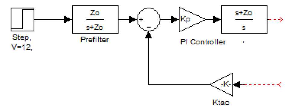
Fig. 9: Simulink block of Proportional-Integral (PI) controller with deadbeat response
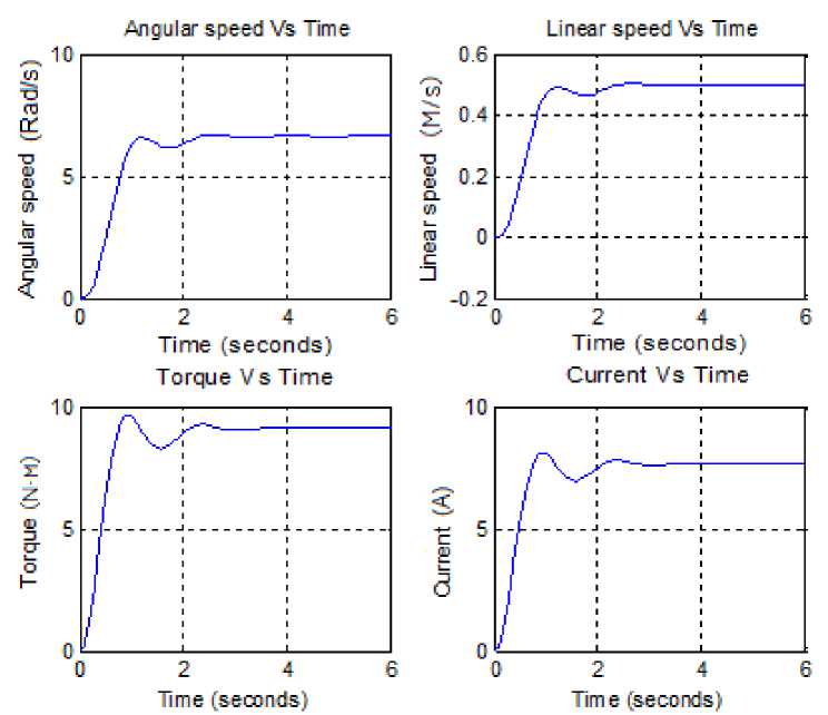
Fig. 10: speed/time, torque/time, speed/time and current/time response curves of the close loop mobile robot system with Proportional-Integral (PI) controller with deadbeat response
-
IV. Circuit Explanation
A simplified version of mobile robot circuit,extracted from [2]and modified, is shown in Fig.11.The inputs are sensors outputs, sensors are line detection sensor-array consisting of with 8 pairs of IR LED/ phototransistor mounted on pitch and the ultrasonic range finder SRF05 sensor. The microcontroller used is PIC16F84A capable of controlling two drive channels; PIC is supplied with 5VDC and simple clock condition with 20 MHz crystal. The outputs are two PMDC motors and a speaker, there are two separate H-bridge circuits to drive motors, The H-bridge circuit is supplied with 12VDC and the four bits outputs of microcontroller made this part to drive the desire conditions of DC Motor. Four NPN transistors are used as switch to choose the direction of current flows to the Motor.
The sensors’ outputs are inputted to the microcontroller, depend on the inputs state, the outputs conditions that controlled the H-bridge circuit are provided by (C+) software.A simplified algorithm for a PID control implementation loop is given next:
Read KP, KI, KP previous_error = 0;
integral = 0;
Read target_position / the required position of robot center.
while ( )
Read current_position; //the current position of robot center with respect to the line.
error = target_position – current_position ; // calculate error proportional = KP * error; // error times proportional gain integral = integral + error*dt; //integral stores the accumulated error integral = integral* KI;
derivative = (error - previous_error)/dt; //stores change in error to derivate, dt is sampling period derivative = KD *derivative;
PID_action = proportional + integral + derivative;
//To add PID_action to the left and right motor speed.
//The sign of PID_action, will determine the direction in which the motor will turn.
previous_error =error; //Update error end
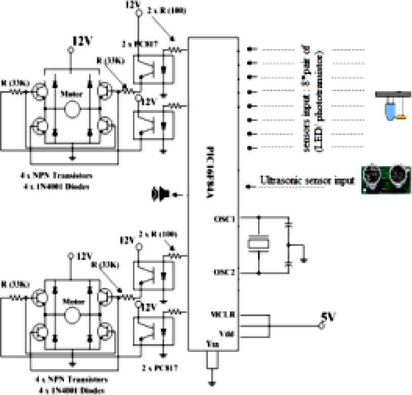
Fig. 11: Microcontroller based PMDC motor control system for mobile robot
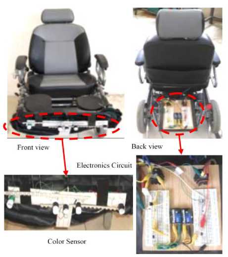
Fig. 12: The designed Mobile Robot, Mechatronics Sec. Lab., Taif University, Taif, Saudi Arabia
-
V. Conclusion
A proposed design of robotic system intended for research purposes as well as for the application ineducational process is introduced.The model of proposed mobile robot was created and verified using MATLAB Simulink software; realexperiments with constructed robot in the form of wheelchair, were accomplished in order to verify the performed simulations. The results confirmed correctness of design of the robotic system.
PID controller enables designer to satisfy all required design specifications,providing almost all the desiredresponse. Itfound that using a PID controller with, suitable gains,all ofthe design requirements wassatisfied;the PMDC motorused reached the desired output angle smoothly andwithin a desired period of time. It has observed that both PMDC motors and PID transfer functions, control have a large influence upon the response of the system.Toachieve a fast response to a step command with minimal overshoot and zero steady state error, so called deadbeat response, can be applied to meet desired specifications.
Nomenclature
|
V, or Vin R a |
The applied input voltage ,(Motor terminal voltage) Armature resistance,( Motor terminal resistance) |
Volte, V Ohm ,Ω |
|
i a |
Armature current |
Ampere, A |
|
K t |
Motor torque constant |
N.m/A |
|
K e |
Motor back-electromotive force constant |
V/(rad/s) |
|
ω m |
Motor shaft angular velocity |
rad/s |
|
т m |
Torque produced by the motor |
N.m |
|
J m |
Motor armature moment of inertia |
kg.m2 |
|
J total |
Total inertia=Jm+Jload |
kg.m2 |
|
L a |
Armature inductance |
Henry , H |
|
b |
Viscous damping, friction coefficient |
N.m/rad.s |
|
e a ,EMF : |
The back electromotive force ,EMF,. EMF =K b dθ/dt |
e a ,EMF : |
|
θ m |
The output angular position of the motor shaft |
radians |
|
ω m |
The output angular speed of the motor shaft |
rad/sec |
|
V R = R*i |
The voltage across the resistor |
Voltage |
|
V L = Ldi/dt |
The voltage across the inductor |
Voltage |
|
T load |
torque of the mechanical load |
T load |
|
Tα |
torque du to rotational acceleration |
Tα |
|
Tω |
torque produced from the velocity of the rotor |
Tω |
|
TEMF |
the electromagnetic torque. |
TEMF |
|
n |
Gear ratio |
|
|
Kp |
Proportional gain |
|
|
K tac |
Tachometer constant |
Acknowledgments
The authoress would like to acknowledge Eng. : Ahmed M. Al-otaibi, Mechatronics Section, Taif University, for his help during this work.
References Mechatronics Design of a Mobile Robot System
- W. P. Aung, Analysis on Modeling and Simulink of DC Motor and its Driving System Used for Wheeled Mobile Robot, World Academy of Science, Engineering and Technology 32 2007.
- Bashir M. Y. Nouri, modeling and control of mobile robot, Proceeding of the First International Conference on Modeling, Simulation and Applied Optimization, Sharjah, U.A.E. February 1-3, 2005.
- http:// webdelcire.com/wordpress/archives/527(with permission)
- H. Alasooly, Control of DC motor using different control strategies, global journal of technology and optimization, volum 2 , 2011.
- R. C. Dorf and Robert H. Bishop. Modern Control Systems. Ninth Edition, Prentice-Hall Inc., New Jersey, 2001.
- B. Shah, Field Oriented Control of Step Motors, MSc. Thesis, SVMITB haruch, India, Dec. 2004.
