Method for Object Motion Characteristic Estimation Based on Wavelet Multi-Resolution Analysis: MRA

Author: Kohei Arai
Journal: International Journal of Information Technology and Computer Science(IJITCS) @ijitcs
Article in issue: 1 Vol. 6, 2014.
Free access
Method for object motion characteristic estimation based on wavelet Multi-Resolution Analysis: MRA is proposed. With moving pictures, the motion characteristics, direction of translation, roll/pitch/yaw rotations can be estimated by MRA with an appropriate support length of the base function of wavelet. Through simulation study, method for determination of the appropriate support length of Daubechies base function is clarified. Also it is found that the proposed method for object motion characteristics estimation is validated.
Object Motion Characteristic, MRA, Wavelet
Short address: https://sciup.org/15012016
IDR: 15012016
Text of the scientific article Method for Object Motion Characteristic Estimation Based on Wavelet Multi-Resolution Analysis: MRA
Published Online December 2013 in MECS DOI: 10.5815/ijitcs.2014.01.05
There are some conventional methods for object detections and object motion characteristics estimations. Optical flow, template matching is well known as the method for object motion characteristic estimations. On the other hands, the method for motion characteristic estimation based on wavelet MRA is also widely used [1]-[9]. Wavelet base function is defined with support length. The most appropriate support length depends on the motion characteristic [10],[11]. Therefore, it is necessary to determine an appropriate support length for estimation of motion characteristics. Meanwhile, it is required to estimate motion characteristics such as translation vector, speed and direction, rotation, direction and speed (rotation angle). 3D object motion characteristics is estimated based on wavelet analysis as well [12].
The method proposed here is based on wavelet MRA with an appropriate support length which is determined by the proposed method and allows estimation of motion characteristics with moving picture. Through simulation study, it is confirmed that the method for appropriate support length is valid together with the method for motion characteristic estimations.
The following section describes the proposed method followed by the simulation study.
-
II. Proposed Method
2.1 Process Flow of the Proposed Method -
2.2 Wavelet Multi-Resolution Analysis: MRA
Fig.1 shows Process flow of the proposed motion characteristic estimations based on wavelet MRA with appropriate support length of base function which is determined by the proposed method. Acquired moving picture is essentially represented in three dimensional space. From the moving picture, the most appropriate support length is determined based on the proposed method which is described in the next sub-section. Then 3D wavelet MRA is applied to the acquired moving picture. As the results from the MRA, motion characteristics are estimated.
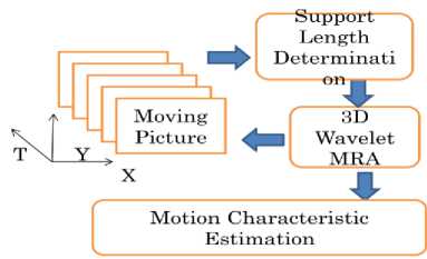
Fig. 1: Process flow of the proposed motion characteristic estimations based on wavelet MRA with appropriate support length of base function which is determined by the proposed method
Two dimensional wavelet transformations is defined by (1).
F = [Cn[Cm fxy]t] (1)
where C m denotes another wavelet transformation matrix while f xy denotes two dimensional data of image. As the result, F=(LL1, LH1, HL1, HH1) with four frequency components in x and y directions, LL1, LH1, HL1, HH1 . Cn can be determined with the method which is described in the second paragraph of this sub-section. Therefore, C n C nt = I . Then f is converted to F 1 =( L 1 , H 1 ), F 2 = C n L 1 =( L 2 , H 2 ), F 3 = C n L 2 =( L 3 , H 3 ), and F m = C n L m-
1 =( L m , H m ). This process is referred to “Decomposition”. Also f is reconstructed as C n-1 F m = C n-1 ( L m , H m ) = L m-1 ,......., C n-1 F 2 = L 1 , C n-1 F 1 = f . This process is referred to
“Reconstruction”. There are some based functions such as Haar, Daubechies, etc. Through the preliminary simulation study with radar echo data, Daubechies base function is selected. Daubechies base function is defined as {α k } satisfying the following three conditions,
ф( x) = V a л/2ф(2 x - k)
k (2)
Pk = (-1) Xk
Ф( x) = V вк ^2ф(2 x - k)
k (4)
where (2) is referred to scaling function while (4) is referred to wavelet function, respectively. There is two-scale relation between the scaling function and the wavelet function. Also, k denotes support length.
Example of the scaling function and wavelet function with support length of four is as follows,
^=W^-o)+^<,(2'-i)+W^^^^
^ = 2^с(2х-о)-^^^(2з-1)+5^г(2х-2)-1^де^
Both functions are shown in Fig.2.
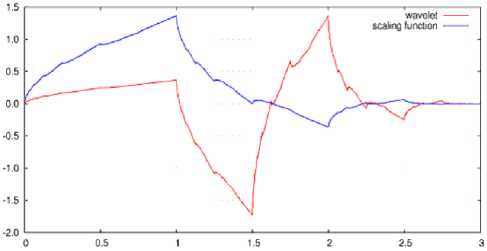
(a)Support length=4
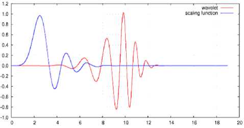
(b)Support length=20
Fig. 2: Scaling and wavelet functions with the different support length
P 0 x 1 + P 1 x 2 q o n + q i n 2 P о П 3 + Р 1 П 4 q o n з + qxn 4 P 0 П 5 + P 1 П б q o n 5 + q n 6 P о П 7 + P ^ o . q o n 7 + q n
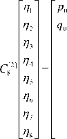
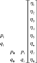
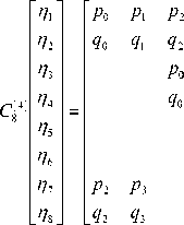
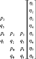
where [n] denotes support length. The 8th order of C n with the support length of four is also expressed with (6).
Method for determination of Daubechies wavelet coefficients is as follows,
For instance, the 8th order 1 of Daubechies base function based C n with the support length of two can be expressed with (5).
1 Scalar data consist of eight numerical data, η 1 to η 8 is assumed.
P о П 1 + P 1 n 2 + P 2 П з + P з П 4 q о П 1 + q 1 n 2 + q 2 П з + q з П 4
P o n 3 + P 1 n 4 + P 2 n 5 + P з П 6 q о П з + q 1 n 4 + q 2 n + q з П 6
P o n 5 + P n 6 + P 2 n 7 + P з П 8 q o n 5 + q 1 n 6 + q 2 n 7 + q з П 8 P o n 7 + P 1 n 8 + P 2 n 1 + P з П г . q « n 7 + q 1 П 8 + q 2 П 1 + q з П 2
p i and q i in (5) and (6) is also expressed with (7) and (8), respectively.
[2] T [2] nnn
P 0 + P i = V2 q о = P i q i = - p о 0 0 q 0 + 1 0 qx = 0
X
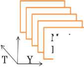
Moving Picture
Different support length of Wavelet Transformatio \____D—___/
C .L: < / i n
P 0 + P i + P 2 + P 3 = V2 q 0 = p з q i = - p 2 q 2 = P i
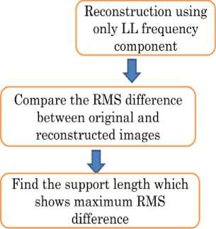
Fig. 3: Method for the most appropriate support length determinations
q з = - p 0
00 q 0 + i0 qx + 20 q 2 + 30 q 3 = 0
0i q 0 + ii qx + 2i q 2 + 3i q 3 = 0
These equations can be expanded to the general support length of C n as shown in (9).
( C [sup] ) T с [SUP]
= In
sup - i
S P j = V2
j = 0
q j ( i ) P ((sup - i) - j )
( j = 0,i,2,...,(sup - 1) )
sup - i
S jrq>=0
= 0
^ r = 0,i,2,...,(sup - 1) ^
Therefore, the coefficients of the Daubechies base function can be determined from the solution of (9).
Wavelet transformation with the different support length is applied to the original image. Then reconstruct the image with the decomposed images of LL component only. If the original image does not have any high frequency components, then LL component is totally equal to the original image. It is not always. Usually, most images have some extent of high frequency components results in the reconstructed image with LL component only is different from the original image obviously.
High frequency components are depends on the spatially and temporally changes in the original image. Therefore, if the Root Mean Square: RMS difference between the reconstructed and the original image is zero, then it may say that there is no high frequency component in the original image. Nevertheless the original image contains relatively large high frequency components, RMS difference is small then it may also say that the spatial and temporal changes cannot be extracted effectively. Consequently, it may say that the support length of which wavelet transformation with the different support length of base function is applied to the original image is the most appropriate if the RMS difference is maximum.
2.3 Method for Most Appropriate Support Length Determinations
Fig.3 shows process flow of the proposed most appropriate support length determination method.
III. Simulation Study3.1 Simulation Data Used
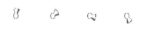
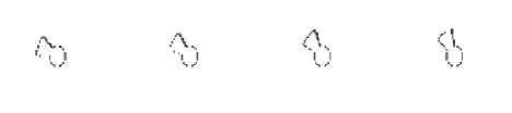
32 frames of time series of shuttlecock like simulation images are crated with PovRay of Computer Graphics software. Translations in vertical, horizontal, and slant directions, and the rotations in pitch, roll, and yaw directions are taken into account as motion characteristics. One of the examples of the moving
picture of shuttlecock for the rotation in pitch direction is shown in Fig.4.
3.2 Simulation Procedure
(b)Vertical
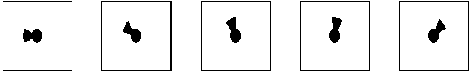
Fig. 4: Example of the moving picture of shuttlecock for the rotation in pitch direction
2D wavelet transformation is applied to the simulation data of moving pictures. Then the reconstructed images are created with HL, LH, and HH components only. Thus the changed pixels or edge pixels are extracted. The changed pixels are counted after the thresholding (binarizing) with an appropriate threshold.
-
3.3 Simulation Results
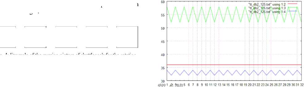
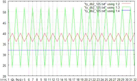
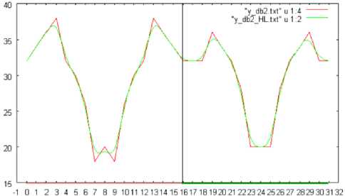
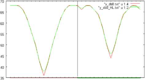
Fig.5 shows the number of changed pixels in the directions of vertical (Red), horizontal (Blue), and slant (Green), respectively when the shuttlecock moves in the directions of vertical, horizontal, and slant (45 degree). The resultant graphs are quite reasonable. In this case, the changed pixels are extracted based on the wavelet transformation with the Daubechies base function of support length of two. Therefore, it is possible to find the moving directions easily. On the other hands, Fig.6 shows the number of changed pixels when the shuttlecock moves in horizontal direction. In this case, the changed pixels are extracted based on the wavelet transformation with the Daubechies base function of the different support length, 2, 4, and 8.
Fig.6 (a), (b), and (c) shows the number of changed pixels extracted from the wavelet transformation with the Daubechies base function of the support length of 2, 4, and 8, respectively.
It is quite obvious that the extracted changed pixels depend on the support length as shown in Fig.6. Also, it is found that support length of 4 is the most appropriate.
(c)Horizontal
Fig. 5: The number of changed pixels in the directions of vertical (Red), horizontal (Blue), and slant (Green), respectively when the shuttlecock moves in the directions of vertical, horizontal, and slant (45 degree). Changed pixels are extracted based on the wavelet transformation with support length of two
(a)Support length=2
(a)Slant
(b)Support length=4
?09, °12*2.^23 4 5 6 7 8 9 10 11 12 13 14 15 1В 17 18 19 2D 21 22 23 24 25 26 27 28 29 30 31
(c)Horizontal
(c)Support length=8
Fig. 6: The number of changed pixels when the shuttlecock moves in horizontal direction. In this case, the changed pixels are extracted based on the wavelet transformation with the Daubechies base function of the different support length, 2, 4, and 8
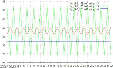
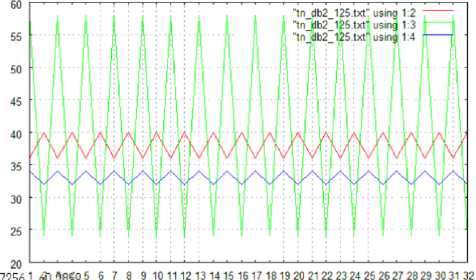
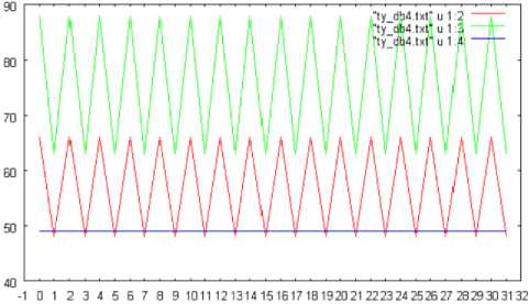
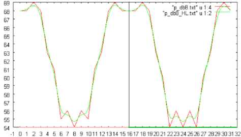
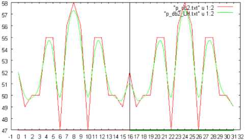
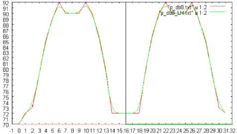
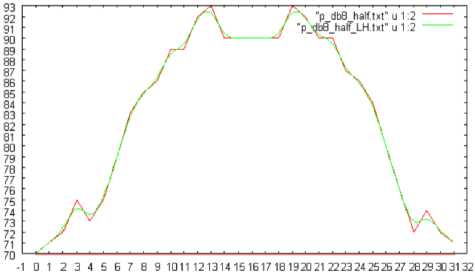
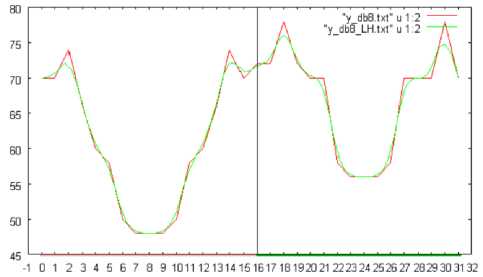
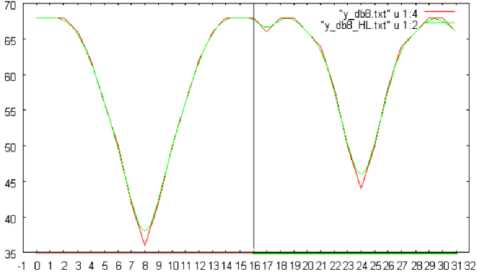
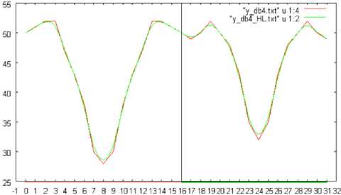
Fig.7 shows the number of changed pixels in the directions of slant, vertical, and horizontal. In this case, shuttlecock rotates from 0 to 360 degrees in pitch direction. The changed pixels are extracted based on the wavelet transformation with the Daubechies base function of support length of 8. Meanwhile, Fig.8 (a), (b), and (c) show the number of changed pixels in vertical direction, for the support length of 2, 4, and 8, respectively. Fig.9 (a), (b), and (c) show the number of changed pixels when the shuttlecock is rotated by 180, 360, and 720 degrees, respectively.
Fig. 7: the number of changed pixels in the directions of slant, vertical, and horizontal. In this case, shuttlecock rotates from 0 to 360 degrees in pitch direction. The changed pixels are extracted based on the wavelet transformation with the Daubechies base function of support length of 8
(a)Support length=2
(a)Slant
(b)Support length=4

(b)Vertical
(c)Support length=8
Fig. 8: The number of changed pixels for the support length of 2, 4, and 8
(a) 180 degree
(a)Slant
(b) 360 degree
(b)Vertical
■1 0123456789 1011 121314151017 181Э20 21 222324 252627 2В29 303132
(c) 720 degree
Fig.9: The number of changed pixels when the shuttlecock is rotated by 180, 360, and 720 degrees
(c)Horizontal
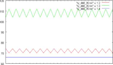
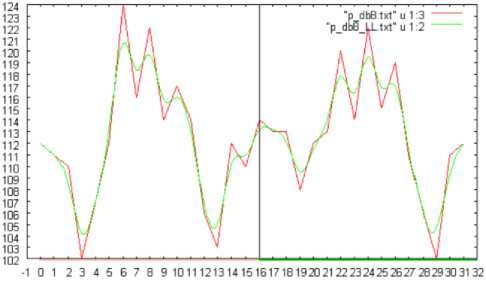
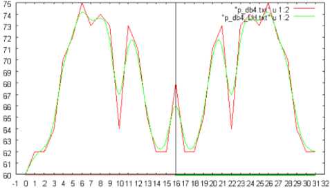
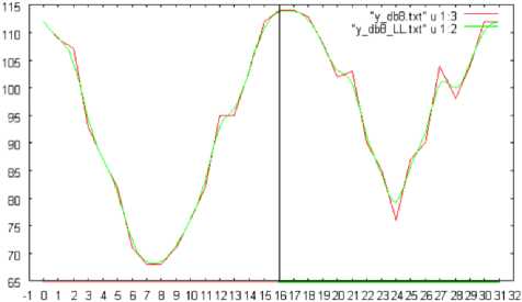
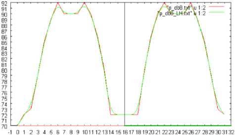
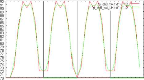
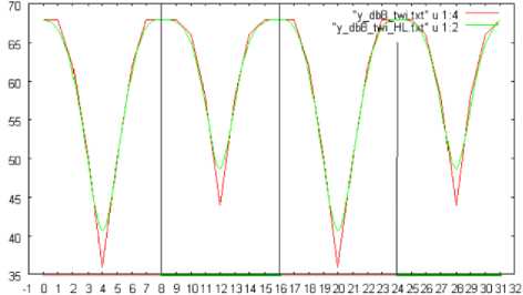
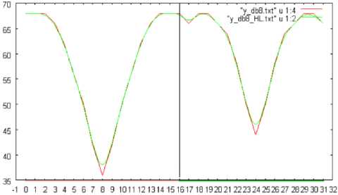
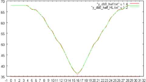
Fig.10 (a), (b), and (c) shows the number of changed pixels in the slant, vertical, and horizontal directions, respectively, which are extracted based on the wavelet transformation with Daubechies base function of the support length of 8. In this case, the shuttlecock is rotated in pitch direction by 360 degrees. Meanwhile, Fig.11 (a), (b), and (c) shows the number of changed pixels in the horizontal direction which are extracted based on the wavelet transformation with Daubechies base function of the support length of 2, 4, and 8, respectively. In this case, the shuttlecock is rotated in pitch direction by 360 degrees.
Fig.12 (a), (b), and (c) show the number of changed pixels in horizontal direction, when the shuttlecock is rotated by 180, 360, and 720 degrees, respectively.
Fig. 10: The number of changed pixels in the slant, vertical, and horizontal directions, respectively, which are extracted based on the wavelet transformation with Daubechies base function of the support length of 8. In this case, the shuttlecock is rotated in pitch direction by 360 degrees
(a)Support length=2
(b)Support length=4
(c)720 degree
Fig. 12: The number of changed pixels in horizontal direction, when the shuttlecock is rotated by 180, 360, and 720 degrees, respectively
(c)Support length=8
Fig. 11: The number of changed pixels in the horizontal direction which are extracted based on the wavelet transformation with Daubechies base function of the support length of 2, 4, and 8, respectively. In this case, the shuttlecock is rotated in pitch direction by 360 degrees
(a) 180 degree
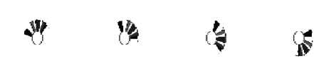
Fig.13 shows the edge enhanced images by 2D and 3D Discrete Wavelet Transformation: DWT with Daunechies base function of support length of 2 and 8 when the shuttlecock rotated in pitch and yaw angles with 90 and 360 degrees.
In general, the number of edge, or changed pixels extracted by 2D DWT is less than that by 3D DWT. Therefore, 3D DWT is much effective than 2D DWT. Also the number of edge, or changed pixels by DWT with support length of 2 is less than that with support length of 8. Therefore, DWT with support length of 2 is effective to extract edge, or changed pixels for the object which moves fast while DWT with support length of 8 is effective to extract edge, or changed pixels for the object which moves slowly. The terminology of fast and slowly implies the moving speed of the object referencing to the frame rate.
(a)360 degree, support length=2, pitch, 3D DWT
(b)90 degree, support length=2, pitch, 3D DWT
■1 О 1 2 3 4 5 6 7 В 9 1011 12 1314 15 1617 18 19 20 21 22 23 24 25 2Б 27 28 2S 30 3132
(b) 360 degree
(c)360 degree, pitch, support length=8, 3D DWT

(d)90 degree, pitch, support length=8, 3D DWT

(e)360 degree, pitch, support length=2, 2D DWT
(f)90 degree, pitch, support length=2, 2D DWT
(n)90 degree, yaw, support length=2, 2D DWT
(g)360 degree, pitch, support length=8, 2D DWT
(o)360 degree, yaw, support length=8, 2D DWT
(p)90 degree, yaw, support length=8, 2D DWT
Fig. 13: Edge enhanced images by 2D and 3D Discrete Wavelet
Transformation: DWT with Daunechies base function of support length of 2 and 8 when the shuttlecock rotated in pitch and yaw angles with 90 and 360 degrees
(h)90 degree, pitch, support length=8, 2D DWT
(i)360 degree, yaw, support length=2, 3D DWT
(j)90 degree, yaw, support length=2, 3D DWT
(k)360 degree, yaw, support length=8, 3D DWT
(l)90 degree, yaw, support length=8, 3D DWT

(m)360 degree, yaw, support length=2, 2D DWT
-
IV. Conclusion
Method for object motion characteristic estimation based on wavelet Multi-Resolution Analysis: MRA is proposed. With moving pictures,
-
(1) The motion characteristics, direction of translation, roll/pitch/yaw rotations can be estimated by MRA with an appropriate support length of the base function of wavelet.
-
(2) Through simulation study, method for determination of the appropriate support length of Daubechies base function is clarified.
-
(3) Also it is found that the proposed method for object motion characteristics estimation is validated.
-
(4) The number of edge, or changed pixels extracted by 2D DWT is less than that by 3D DWT. Therefore, 3D DWT is much effective than 2D DWT.
-
(5) Also the number of edge, or changed pixels by DWT with support length of 2 is less than that with support length of 8. Therefore, DWT with support length of 2 is effective to extract edge, or changed pixels for the object which moves fast while DWT with support length of 8 is effective to extract edge, or changed pixels for the object which moves slowly. The terminology of fast and slowly implies the moving speed of the object referencing to the frame rate.
Acknowledgment
The author would like to thank Mr. Yuji Yamada for his effort to conduct the simulation study.
References Method for Object Motion Characteristic Estimation Based on Wavelet Multi-Resolution Analysis: MRA
- K. Arai K. et al., Takagi and Shimoda edt., Image Analysis Handbook, Tokyo Daigaku Shuppan-kai publishing (1991).
- K. Arai K., Fundamental theory for image processing, Gakujutsu-Tosho Shuppan Publishing Co., Ltd (1996).
- K. Arai K., Methods for Image Processing and Analysis of Earth Observation Satellite Imagery Data, Morikita Shuppan Publishing Co., Ltd (1998).
- K. Arai and L. Jameson, Earth observation satellite data analysis based on wavelet analysis, Morikita-Shuppan Publishing Co., Ltd (2001).
- K. Arai K., Java based Earth observation satellite imagery data processing and analysis, Morikita-Shuppan Publishing Co., Ltd (2002).
- K. Arai, K.Seto, Dynamic characteristic idetification of moving objects based on wavelet analysis, Journal of Visualization Society of Japan, 24, Suppl.1, 227-230 (2004)
- K.Arai, K.Seto, T. Nishikawa, Methid for dyanamic characteristic identification of rotated accelerated object based on wavelet analysis, Journal of Visualization Society of Japan, 26, Suppl.1, 145-148, 2006
- K.Arai, T. Nishikawa, Dangerous car identification based on wavelet analysis, Journal of Visualization Society of Japan, 27、Suppl.1、217ー220、2007
- K.Arai, T.Nishikawa, Identification method for moving object in remote sensing satellite images based on wavelet analysis, Journal of Visualization Society of Japan, 29, Suppl.1, 163-166, 2009.
- K.Arai, T.Nishikawa, Method for optimum support length determinations of Daubechies base function of wavelet in moving object detection of remote sensing satellite images, Journal of Visualization Society of Japan, Journal of Japan Society of Photogrammetry and Remote Sensing, 48、3、171-179、2009.
- K.Arai, Yuji Yamada, Method for determination of optimum supoort length of base function of wavelet for change detection, Journal of Visualization Society of Japan, 29、Suppl.2,83-86, 2009
- K.Arai, Yuji Yamada, Analysis method for 3D object moements based on wavelet analysis. Journal of Visualization Society of Japan, 30,Suppl.2,287-288,2010.
