Methodology for calculating the de-weighting system of large-sized transformable elements of space vehicles for ground tests

Author: Belyaev A. S., Filipas A. A., Tsavnin A. V., Tyryshkin A. V.
Journal: Siberian Aerospace Journal @vestnik-sibsau-en
Section: Aviation and spacecraft engineering
Article in issue: 1 vol.22, 2021.
Free access
This paper considers the methodology for calculating the de-weighting system of spacecraft elements for ground tests, taking into account the deployment options, de-weighting conditions, types and options of de-weighting systems. An example of calculation for a 3-section solar battery without a beam with incomplete de-weighting and with minimization of moments in the hinges is given. Genetic algorithms are used as an algorithm for determining the parameters of the de-weighting system, which allows obtaining the minimum moments in the hinges. The moments and forces acting in the system were checked by plotting diagrams in the expanded state. In addition, a check for compliance with the specified distance, based on design constraints, between the points of application of the weighting forces was made.
Deweighting, spacecraft, testing in ground conditions, automatic control systems, parametric uncertainty.
Short address: https://sciup.org/148321791
IDR: 148321791 | UDC: 531.133.3 | DOI: 10.31772/2712-8970-2021-22-1-106-120
Text of the scientific article Methodology for calculating the de-weighting system of large-sized transformable elements of space vehicles for ground tests
Introduction. The current state of space technologies involves the deployment of a large number of propulsion, energy and information systems in the near and far space. The technical requirements for these systems, along with high reliability, safety and efficiency, contain strict weight and size indicators. Delivery vehicles impose restrictions on the mass and size characteristics of spacecraft, which, in turn, makes foldingtype structures application. For guaranteed successful deployment of spacecraft, it is extremely necessary to conduct ground tests of all systems. One of the key aspects of spacecraft testing is the calculation of mechanical strength for zero-gravity conditions, what significantly complicates the conduction of full-scale testing of equipment in the presence of gravity. The main method for solving these problems is the development of special de-weighting systems, which, taking into consideration the requirements to the deployment process and the design features, makes it possible to conduct tests in ground conditions in all possible modes of deployment and functioning.
There are 3 types of de-weighting systems: passive, passive-active and active. In turn, all the presented systems can be of support or cable type. Passive weight control systems basically use a counterweight to compensate the weight of the de-weighting element (DE). Systems of this type are simple in construction and are not expensive, however, the inability to change the deflection forces during the deployment process is a significant disadvantage, since the emergence of dynamic moments of resistance because of deflection errors cannot be compensated. Another disadvantage of this type of de-weighting systems is the large weight and size characteristics. Application of a controlled electric or hydraulic drive as a device which creates the deweighting force makes it possible to change the de-weighting force during the deployment process, as well as reduce the weight and size characteristics of the system. Such systems are called passive-active [4,5]. However, the movement of the de-weighting system itself, as in the case with passive systems, is carried out due to the movement of the DE, which leads to the emergence of friction moments in the hinges, the "effect of attached masses", as well as inaccuracies in the calculations of the energetics of the deployment system of spacecraft elements. These disadvantages are absolutely eliminated in active de-weighting systems, the movement of which is carried out due to the installed electric motors [6,7,8]. It should be noted that because of the complexity of control algorithms for this type of systems, the correct configuration of control loops in some cases is difficult, and also results in a significant increase in the cost of this technical solution. Thus, the problem of unambiguous choosing the type of de-weighting system, taking into consideration the specific technical task, remains unsolved.
Description of the proposed methodology. In this paper, the methodology for calculating the deweighting system for ground tests of spacecraft, including 10 steps, presented below, is proposed.
Step 1. The variety of large-sized transformable structures (LTS) makes the developers to consider the task of designing a de-weighting system, taking into consideration the peculiarities of each individual object. However, to systematize the calculations, it is possible to classify the LTS using method of unfolding (folding), which is based on the trajectories of motion of the associated masses (volumetric, radial, linear, combined, etc.). Differences in the trajectories of deployment and in the mechanics of the systems cause an impact on the process of calculating the de-weighting system. That is why, at the first stage, it is necessary to choose the type of the item to be de-weighted, which, in most cases, is determined rightly in the task set before the performers.
Step 2. After completion of the first step, it is necessary to determine the limitations and tolerances for de-weighting. The characteristics which affect the quality of de-weighting include moments in the hinges, centrifugal moments, dynamic and static moments of inertia. Thus, at this stage, the choice of the necessary de-weighting condition is performed on the assumption of the technological requirements for DE. Further, we will consider in detail the possible variants of de-weighting according to the requirements.
The most common variant is complete de-weighting, in which there is a full compensation of the weight of the DE and limiting the moments to the maximum allowed values, based on preliminary design calculations according to the conditions of mechanical strengths, permissible deformations, etc. The realization of this condition is possible with full compensation of the DE weight by their centers of mass, or application of several de-weighting devices for one DE. However, in such cases, because of the deflection error, additional moments of friction of the hinges are created. For such conditions, all types of de-weighting systems can be used.
The second variant is to compensate moments or forces at arbitrary points, for example, in the centers of mass of the DE or at the hinges. This task is actual in most cases, as the deployment of spacecraft elements during ground experiments friction moments in the hinges, which interfere with the deployment process and reduce the energy of the deployment system, cause the biggest problem. In addition, in the process of opening, deviations from the normal mode arise, in terms of acceleration, unevenness, the influence of the deweighting system, air resistance, etc. For such kinds of restrictions, it is possible to use exclusively active deweighting systems, as other types of systems will create moments of friction in the hinges, caused by the "effect of added masses".
The third variant is compensation of the centrifugal, dynamic and static moments of inertia which appear during the deployment process. This option is not so widespread, however, when using support systems for weighting, these moments lead to "breaking" of the hinges, what leads to a malfunction of the system and its failure. This variant is not so widely used, however, when using support de-weighing systems, these moments lead to "breaking" of the hinges, what results in a disturbance of the system functioning and its failure.
The basic conditions for de-weighting having been chosen, it is necessary to determine the number of devices or elements, which the system is composed from.
Step 3. From the point of view of DE strength calculations, there are maximum allowable forces which DE can withstand at critical and (or) arbitrary specified points, including the hinges. Thus, a necessary condition for the system functioning is that the moment at any point of the structure must be less than the maximum allowable. Based on this fact, it is necessary to determine the minimum required number of elements of the de-weighting system. For this, the principle of decomposition is applied - DE must be considered as a system consisting of separate sections, which are affected by a distributed load equal to the weight of the DE, limited by the points of interaction with the elements of the de-weighting system. After that, it is necessary to determine the point at which the maximum moment acting on the section is concentrated, and to determine the dependence between the length of the section and the moment at this point. Having this dependence and the maximum permissible moment obtained from strength calculations, it is possible to determine the maximum length of one section and, as a consequence, the minimum required number of elements of the deweighting system.
Step 4. After determining the minimum number of elements of the de-weighting system, it is necessary to calculate diagram and moments acting in the system. For this, at first, it is necessary to determine the relationship between the parameters of the de-weighting system and the parameters of the DE. As the parameters of the de-weighting system the position of the fixing point of the element (x ) of the de-weighting system to the i of DE, and the force of weight compensation P , i= 1, N, where N is the amount of DE is used. The weight F and length of the element L are used as the DE parameters at this stage.
It should be noted that the maximum allowable efforts can have different values at different points and, accordingly, the load diagram can have a complex form, and the calculations of the point (points) of the maximum allowable moment will not be single.
Another feature is the possible non-uniform movement along the length the mechanical strength of the structure, which can be taken into consideration with the help of diagram of the permissible moment variable along the length.
At this stage, the selected type of element to be de-weighted should be taken into consideration, in particular, an object with a linear trajectory can be presented as a rigidly fixed beam due to its rectilinear shape in the unfolded state, as well as the presence of hinges with increased rigidity to exclude potential backlash and levelling elastic oscillations along the vertical axis of motion. In the case of a radial opening, the structure will be divided into parts by hinges due to the sequential character of the opening.
As in most cases the number of equations obtained as a result of calculating the diagrams will be greater than the number of unknowns, this task can be solved as an optimization one, and the conditions obtained in paragraph 2 can be used as a functional for minimization, i.e.:
-
- minimization of moments at points;
-
- minimization of forces;
-
- minimization of centrifugal and dynamic moments of inertia.
Step 5. During the operation of the de-weighting system, various construction restrictions may arise, the most common is the impossibility of connecting an element of the de-weighting system directly to the center of mass of the item to be de-weighted. In addition, there are possible variants when the trajectories of movement of the de-weighted elements intersect in time, what will lead to collisions and inoperability of the deweighting system. At present, such problems are solved by means of multilevel trajectories or application of various bypass devices, what excludes collisions, in principle, and at the same time significantly complicates the construction of the system, however, for a number of problems, such solutions cannot be used.
Taking into consideration all said above, at this stage it is necessary to determine the main restrictions imposed on the parameters and construction of the de-weighting system.
Step 6. After taking into consideration the restrictions and solving the task of minimizing the main deweighting condition, selected in point 2, we obtain the parameters of the de-weighting system.
Step 7. Having determined the parameters of the de-weighting system, it is necessary to check the obtained results taking into consideration the selected de-weighting condition, for example, for the maximum admissible, from the point of view of the energy of the deployment system, moment in the hinge, and checking the system deployment taking into consideration construction limitations based on the of kinematic equations of the system functioning application. For this, it is necessary to solve the direct task of kinematics and make sure that the de-weighting systems do not intersect along the constructed trajectories of movement.
If one of the conditions is not realized, it is necessary to return to step 3 and increase the number of elements by 1 and repeat steps 4–7. If all the conditions have been performed, then one can proceed to the choice of the type of de-weighting system.
Step 8. The next step is to determine the type and performance of the de-weighting system, taking into consideration the conditions described in the paragraphs above. As active de-weighting systems, rope systems based on the use of carriages moving along fixed rails, on which electric drives are installed, creating a compensation force, and moving carriages, have received the greatest application. Such systems are used both for de-weighting of spacecraft elements [8] and for compensation of the weight of sick patients in medicine [9]. However, because of the fact that in the folded state the elements of the spacecraft are located closely to its body, the necessity to use complex design contours arises. This problem can be solved by a system, consisting of inclined ropes, which is used in medicine [10]. The system can consist of 4, 8 or more cables and, by changing the tension force and their length, move the de-weighted structure [11]. In addition, it is possible to use a carriage with inclined rope systems installed on it, what will increase the speed of working out the deflection system when de-weighting. Variants of rope de-weighting systems are shown in Fig. 1.
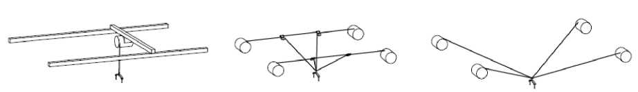
Рис. 1. Варианты тросовых систем обезвешивания
-
Fig. 1. Variants of rope weightlessness imitation systems
Another solution is to use support systems for de-weighting [12], for this robotic platforms with a support installed on them and a system which allows to determine and track changes in the position of the deweighting element, taking into consideration the requirements for the formation of the moment (force) of weight compensation in point of application can be used.
Step 9. The penultimate stage is the synthesis of the automatic control system. Considering the process of operation of both rope and support systems of de-weighting, because of the movement of the DE along the axis of the opening, an error of deviation occurs between its position and the element of the de-weighting system. When moving along several axes, an error occurs in the form of a directed vector, which must be compensated.
Step 10. The final stage is checking the operation of the whole system, taking into consideration the dynamics of the deployment, which can be sequential, simultaneous and combined. The opening dynamics influences the distribution of forces and moments, therefore, it is necessary to take into account the opening variant when calculating the de-weighting system. The most often used options are sequential and simultaneous deployment, which introduce insignificant influence into the calculation of the de-weighting system. However, the occurrence of non-standard situations leads to significant changes in the dynamics of deployment and, as a consequence, to the moments and forces acting in the system in the process of deployment. From all of the above, it is necessary to carry out a dynamic check of the operability of the de-weighting sys- tem, that is, working out the basic de-weighting conditions, with different deployment variants, both standard and non-standard.
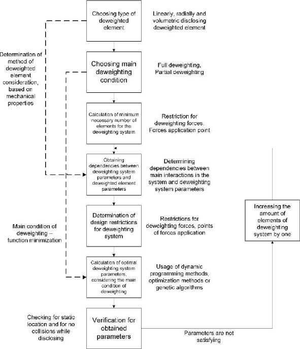
At this stage, it is possible to determine the moments of inertia of the elements of the mechanical system, including variables. It should be noted, that the peculiarity of this stage is the definition of intervals of changes of mechanical parameters (for dynamics and statics). In the process of deploying solar panels of a spacecraft, the ratios of the positions of the de-weighted elements change, which leads to a complication of the panel kinematics, which, in turn, introduces additional structural uncertainty determined by a change in the order of the system of differential equations. In the process of opening the solar panel of a spacecraft, at the beginning of the movement of each of the elements, their influence on the dynamics of each other changes, which, accordingly, complicates the parametric uncertainty, which, in this case, will be described not by interval, but by affine, multilinear or polynomial types of parametric uncertainty [13; 14]. The complication of the type of parametric uncertainty significantly complicates the procedure for synthesizing the control system. A diagram of the calculation methodology is shown in Fig. 2.
Parameters are satisfying
Choosing the type of deweighting system
Support system or cable system. Passive, active and passive, active
Deweighting system algorithm implementation
Tracking system, predictive control, control with reference model
Verification of workability of deweighting system via dynamic model
Рис. 2. Схема методики расчета
-
Fig. 2. Calculation method workflow
An example of calculating a solar battery de-weighting system.
Step 1. As an object for demonstration the operation of method of calculation, we use a linearly deploying solar battery, without a beam, consisting of 3 panels. In this calculation, the beam of the solar battery can be neglected because of its insignificant mass in relation to the weight of the solar panel. We take the mass of the panels equal to 40 kg, the length of each panel is 4 meters. We take the following statement as a limitation: in the folded state, the distance between the points of the application of de-weighting forces must be at least 0.6 m.
Step 2. As a condition for de-weighting, we will choose partial de-weighting with minimization of moments in the hinges between the DE. On condition that the sum of the forces in the supports should be equal to the sum of the weights of the elements being de-weighted, the parameters of the de-weighting system should be selected based on the necessity to minimize the moments in the hinges.
Step 3. Suppose that the maximum moment which the panel can withstand is 0.24 kNm. Then, as discussed earlier, the de-weighted structure can be considered as a section bounded by 2 supports, which is acted upon by a distributed load equal to the ratio of the panel's weight to its length, that is:
F q=L
= 0,1 kN/m
where F is the panel weight equal to 400 N, and L is the panel length equal to 4 m.
Let the section be bounded on the left side by a support A in which the reaction of force R will act, and on the right side - by a support B , in which the reaction of force R will act, and what is more, these forces will be equal. Then when calculating the diagrams of this system, the maximum moment will be in the center of the beam, to determine which it is necessary to calculate the reaction of the support at the point A or B :
l 2 q Ra = RB = — = q-ABl 2
Then the moment at any point of the beam can be determined as follows:
M ( x ) = - q'^ + Ra • x (1)
Having calculated the moment in the middle of the beam (1), we obtain the following dependence of the length of the section from the moment (2) with numerical solution for the given example:
8 ■ M
l =
max
q
M

q ■ l
8 ■ 0,24
0,1
= 4,38 м
Consequently, since the total length of the de-weighted structure is 12 meters, then at least 4 supports are required, one of which will be the spacecraft body. As a result, at this step, the minimum required number of additional supports, equal to 3, was determined to de-weight the solar panel.
Step 4. Let's determine the relationships between the forces and moments acting in the system. We consider a solar battery in its final, unfolded state. Since the hinges for solar panels are made with minimal back- lash, it is possible to consider the construction as a single rigid structure, i.e. a rigidly fixed beam at point A. Then the equations of the moment and the reaction force at point A, as well as the equations of moments in the hinges, can be determined as follows:
MA = - F 1 ■ 1 - - F 2 ■f l 1
I- lr— I
+ 2 I F 3 I l1 + 1 2 + 2 I P 1 x 1 P 2
■ x 2 - P3 ■ x3
R a =- F 1 - F 2 - F 3 - P 1 - P 2 - P 3 ,
M 1 = MA + RA • 1
—
F 1 •
—
P 1
( l1 - x 1 ) ,
( l
\
M 2 = MA + RA '( l 1 + 1 2) — F 1 • 7+ l
к
-
P 1( l 2
-
x 1) F2 •
l
к
-
P 2( l 2
—
x ) ,
where l is the length of the i-th panel, i e [1; 3], F. is the weight of the i -th panel, P is the weighting force i ii of the i-th element of the de-weighting system.
The number of unknown variables in (3–6) is 6. Let us denote the unknown variables as a vector
X = (x, x2, x3, p, P, P ). Since the condition of minimizing the moments in the hinges is chosen as the main condition for de-weighting, and the moments can be both positive and negative, then the sum of the moment modules in the hinges is chosen as the minimization function lim x
(I Ma I + | M 1I + l M 2I)
^ 0
Step 5. As a restriction, we set the distance between the points of application of the de-weighting forces in the folded state. This distance must be not less than 0.6 m. In addition, the selected minimal distance between the points must be kept during the deployment process.
Since each de-weighting device must create a force directed opposite to the weight of the de-weighted elements, the values will be negative. In analogy, we introduce a restriction on the maximum module value of the force provided by the element of the de-weighting system, for example, 1 kN. Then limitations of the vector look like this:
^x1 e[0;4], x2 e[4;8], x3 e[8;12], кP1 e[—1;0],P2 e[—1;0],P3 e[—1;0]v
I x 1 — ( x 2 — 4)| > 0,6
«| x 1 — ( X 3 — 8)| > 0,6
J ( X 3 — 8) — ( x 2 — 4)| > 0,6
Step 6. Let's proceed directly to determining the optimal values of the vector. Genetic algorithms were chosen as a method for searching the minimum value. A genetic algorithm is an optimization method based on the principle of crossing biological genes, which allows to optimize multipara meter functionals. The algorithm works as follows: for the genetic algorithm to work, it is necessary to set the structure of the individual, as which the vector X = (x^, x2, x3, p, p, p ) was chosen. At the first stage, the algorithm creates 200 individuals (user-specified value), this value is called the population size, with random vector X values. Using (3-6) for each individual, the moments at a point A, joints and the value of the minimization function are determined. After that, all the obtained individuals are ranked according to the values of the target function, and this population becomes the parent population. After that, a new population is created, and 5% of the new population will be the best individuals of the parental population without changes, 80% will be individuals obtained as part of crossing the best individuals of the parental population, and the remaining 15% will be obtained as a part of the mutation of random individuals of the parental population. As a result, a new population of 200 individuals is formed, for which the necessary calculation of the moments and the minimization function will also be performed, and the population will become the parental for the new selection. Such repetitions happen until the stop criterion by the number of iterations is triggered (5000 iterations) or until the value of the minimization function decreases significantly for 5 consecutive iterations. The implementation of the work of the genetic algorithm was carried out in the Matlab 2017 environment using the Optimization Toolbox package. The result of the genetic algorithm is shown in Table 1, and the minimization process in time is shown in Figure 3.
Table 1
Parameters of the de-weighting system obtained with genetic algorithms application
|
X1 |
X2 |
X3 |
P1 |
P2 |
P3 |
|
1,075 |
6,064 |
10,741 |
–0,413 |
–0,597 |
–0,292 |
Step 7. Let’s check the results obtained by plotting the forces and moments acting in the system with the obtained parameters of the de-weighting system (Fig. 3).
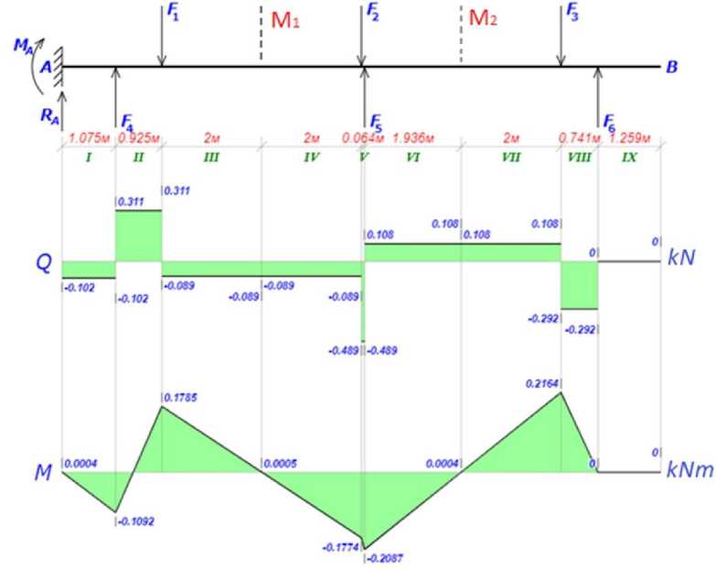
Рис. 3. Эпюры сил и напряжений с полученными параметрами системы обезвешивания
Fig. 3. Diagrams of forces and stresses with the obtained parameters of the weightlessness imitation system
According to the diagrams, it can be seen that the moments in the hinges are equal to 0.4, 0.5 and 0.4 Nm, accordingly; in addition, the maximum moment at the panel point is 0.216 kNm, which does not exceed the previously set maximum permissible moment equal to 0.24 kNm.
As the check for the location of the elements of the de-weighting system in a static position was established as a limitation, then checking this condition is redundant. Accordingly, we will check for the absence of collisions of the elements of the de-weighting system during deployment. For this, as noted earlier, the distance between the points of application of the force should not be less than 0.6 m.
Let's define the kinematics of the solar panel deployment. For this, we will use the method proposed in [15-16]. Let's designate each solar panel element with an ordinal number, from left to right, as shown in Figure 4. Since each solar array hinge allows rotation only about the vertical Z axis in the global coordinate system, each hinge can be represented as a rotary link, described by matrix WR3, and solar panels and a beam are described by matrices WP2, depending on the length of these links [15-16]:
|
cos ( a ) - sin ( a ) 0 0 |
" 10 0 0 |
||
|
WR 3 ( « )□ |
sin ( a ) cos ( a ) 0 0 0 0 10 |
WP 2 ( l ) = |
010 l 0010 |
|
_ 0 0 0 1 _ |
_ 0 0 0 1 |
Each of the rotation angles will be determined relative to the previous structure, that is, the angle q1 rela- tive to the ground structure, q2 relative to the solar panel 2, and the angle q3 relative to the panel 4.
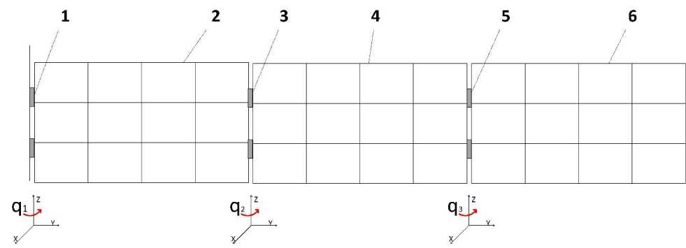
Рис. 4. Кинематическая схема солнечной панели
Fig. 4. Kinematic diagram of a solar panel
Using the methods described in [15-16], we obtain the finite matrices of each of the supports, denoted as
|
Ti , then: |
T 1 = WR 3( q 1 ) • WP 2( X 1 ) (7) T = WR 3( q ^) • WP 2( L ) • WR 3( ^ 2 ) • WP 2( ^ 2 ) (8) T 3 = WR 3( q 1 ) • WP 2( L ) • WR 3( q2 ) • WP 2( L ) • WR 3( q3 ) • WP 2( x3 ) (9) |
Having substituted the rotation and transfer matrices into equations (7-9) we obtain the following equations:
T 1
V У J
^ x t cos( qx )л V x sin q^ j
T 3
x
V У J
T 2
V У J
' L cos( qx ) + x 2 cos( qx + q 2 ) V L sin( q 1 ) + x 2 sin( q 1 + q 2 ) ,
^ L cos( qx ) + L cos( qx + q 2 ) + x 3 cos( qx + q 2 + q 3)A V L sin( q 1 ) + L sin( q 1 + q 2) + x3 sin( q 1 + q 2 + q 3 ) ?
Equations (10–12) allow to obtain the coordinates of each of the points of application of the de-weighting force during the deployment process. To determine the distance from one point to another in the process of deployment (Fig. 6), let’s calculate the square root of the sum of the squares of the differences in the coordinates of the points.
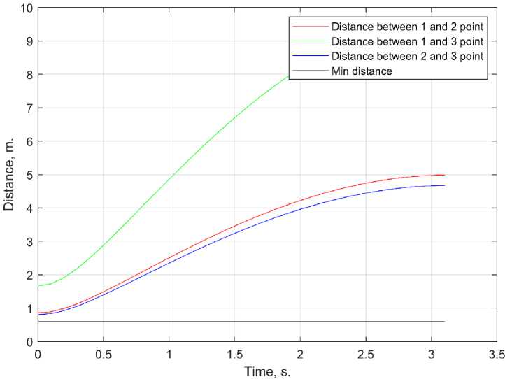
Рис. 5. Расстояние между точками приложения сил во время раскрытия
Fig. 5. The distance between the points of application of forces during deployment
According to the graphs shown in Fig. 5, it is seen that the distance between any of two points of application of the de-weighting forces is greater than the required one, what indicates that the parameters of the deweighting system have been chosen correctly. The last two points of the methodology will be considered in future works.
Conclusion. Within the framework of this work, a method is proposed for the development of a system for de-weighting large-sized transformable elements of spacecraft in ground conditions. This method consists of ten steps, taking into account the type of element to be de-weighted, the requirements for de-weighting, as well as the type of de-weighting system, for example, cable or support ones. The method allows calculating the points of attachment of the elements of the weighting system, depending on the type of the element to be de-weighted, taking into account design limitations. The paper considers an example based on a 3-section solar battery without a beam, for which 8 stages were carried out from the calculation methodology and the attachment points for elements being de-weighted were obtained, taking into account the distance limitations of 0.6 meters. A check of the forces and moments acting in the system in the deployed position was carried out, according to the results of which the admissibility of the calculated characteristics of the de-weighting system was established. In addition, a test was carried out to maintain the required distance during the deployment of the solar panels, which also turned out to be successful.
References Methodology for calculating the de-weighting system of large-sized transformable elements of space vehicles for ground tests
- Bilko V. V., Pletneva N. А., Pletnev V. V. Ispytatelniy stend dly raskrytiya solnechnih batarey [Test Bench for Solar Battery Deployment]. Patent 2 468 969 РФ, МПК7 B 64 G 7/00, 2012.
- Bilko V. V., Pletneva N. А., Sorokoletov V. I., Schuplyk Y. P. Stend raskrytiya paneley solnechnoy batarei [Solar Panel Deployment Stand]. Patent 2 483 991 RUS, IPC 7 B 64 G 7/00, B 64 G 1/44, 2013.
- Zurfluh E. A. Controlled fiber-optic switch. Patent. 5 110 194 USA, IPC 7 B 64 G 7/00, G 01 M 19/00, 1990.
- Zarnichin А. Y., Malyshenko А. М. [Investigation of the dynamic properties of the vertical channel of the active silo-compensating system]. Ingeneriya dly osvoeniya kosmosa. Tomsk, TPU, 2016, P. 268–269. (In Russ.)
- Hasselman T. K. Microgravity suspension system for simulating a weightless environment. Patent 5 379 657 USA, IPC 7 B 66 F 11/00, G 01 M 19/00, 1992.
- Zarnichin А. Y. [Investigation of the dynamics of tracking systems of a stand with an active dewatering system for testing the deployment of solar cell wings in terrestrial conditions]. Molodezh i sovremennie informachionnie tehnologii. Tomsk, TPU, 2016, P. 268–269. (In Russ.)
- Shpyakin I., Voronin A., Malyshenko A., Majkov S. Modeling of a Solar Arrays Deployment Process at Ground Tests of Mechanical Devices on Active Gravity Compensation Systems. 2018 3rd Russian-Pacific Conference on Computer Technology and Applications (RPC). Vladivostok, 2018, P. 1–4.
- Verhoglyad A. G., Kuklin V. A., Makarov S. N., Mihalkin V. M., Halimanovich V. I. Automated weight compensation system for ground-based tryout of space vehicle solar panels. Siberian Journal of Science and Technology. 2017, Vol. 18, No 3, P. 567–574.
- Vector Clinician's Guide. Available at: https://www.bionessvector.com/documents/Vector%20Clinician's%20Guide%20Rev.%20K%20[efile].pdf (accessed: 4.06.2020).
- Plooij M., Keller U., Sterke B., Komi S., Vallery H., von J. Zitzewitz Design of RYSEN: An Intrinsically Safe and Low-Power Three-Dimensional Overground Body Weight Support. IEEE Robotics and Automation Letters. 2018, Vol. 3, No. 3, P. 2253–2260.
- Karmanova A. V., Filipas A. A. [Study of the model of a three-point crane of flexible suspension]. Aktual'nye problemy innovacionnogo razvitiya yadernyh tekhnologiy. 2016, P. 68–68а. (In Russ.)
- Belyaev A. S., Filipas A. A., Malyshenko A. M., Sumenkov O. Yu. Modeling and control system development for mobile ro-bots for solar panels weightlessness imitation. News of the Tula state university. Technical sciences. 2020, No. 12, P. 3–12. (In Russ.)
- Tsavnin A. V., Efimov S. V., Zamyatin S. V. External boundaries of pole localization region formulation for transfer function with interval-given parameters. Siberian Journal of Science and Technology. 2019, Vol. 20, No. 3, P. 327–332.
- Tsavnin A. V., Efimov S. V., Zamyatin S. V. Providing real closed-loop transfer functions poles for plant with interval-given parameters for overshoot elimination. 2019 11th International Congress on Ultra Modern Telecommunications and Control Systems and Workshops (ICUMT). Dublin, Ireland. 2019, P. 1–7.
- Malishenko A. M. [A formalized method for describing the structures and parameters of kinematic chains of manipulators]. Izvestiya Akademii nayk SSSR, Mashinovedenie. 1989, No. 4, P. 61–67. (In Russ.)
- Malishenko A. M. [Derivation of kinematics equations for a crank-slide mechanism based on a structural-parametric description of its kinematic chain]. Sovremennye tekhnologii, ekonomika i obrazova-nie: sbornik trudov Vserossiyskoy nauchno-metodicheskoj konferencii. Tomsk, TPU. 2019, P. 57–60. (In Russ.)
