Microcantilever: an efficient tool for biosensing applications

Author: Diksha Sharma, Neeraj Tripathi
Journal: International Journal of Intelligent Systems and Applications @ijisa
Article in issue: 10 vol.9, 2017.
Free access
Most of the biosensing applications involving analysis and detection of a particular specimen demands fast, easy to use, less expensive, highly reliable and sensitive method for the recognition of biomolecules. The reason behind this increasing demand is that most of the available laboratory equipment require large space, are highly expensive and have other preconditions. Most of the viscometers available for measuring the rheological properties of blood require cleaning after each use which can be challenging due to the capillary geometry. The substitute to this is microcantilever that has emerged as an ideal candidate for biosensing applications. Microcantilever is capable of being used in air, vacuum or liquid medium. This paper consists of seven sections in which working principle of a cantilever, different modes of vibration, their comparative analysis, analytical equations of hydrodynamic equations exerted by the fluid on the cantilever and their impact on the resonant frequency and quality factor, applications of microcantilever in liquid medium specifically in biomedical field are discussed.
Microcantilever, dynamic mode, resonant frequency, biosensing, rheology
Short address: https://sciup.org/15016428
IDR: 15016428 | DOI: 10.5815/ijisa.2017.10.08
Text of the scientific article Microcantilever: an efficient tool for biosensing applications
Published Online October 2017 in MECS
MEMS(Microelectromechanical systems) is one of the most promising technologies in which several mechanical devices like sensors, actuators, transducers implanted in semiconductor chips are consolidated with computers [1]. The attractive features of MEMS devices are: they are interdisciplinary in nature, exhibits batch production, less expensive, highly miniaturized structure, highly reliable, better performance than other available technologies. Different biosensors, blood pressure sensors, microviscosity sensors, microcantilevers, micropumps, microvalves, micro flow sensors, optical switches, airbag sensors, all come under the category of MEMS devices [2]. MEMS biosensors are utilized for studying intermolecular interactions, for microfluidic rheometry [3] i.e. measuring rheological (mechanical) properties of different fluids, in Diagnostic and Translational applications [4]. The Global Positioning system can be used for tracking purposes and much more.
Since we are focusing on biosensing applications, for that purpose MEMS-based microcantilever sensor is studied. In biomedical applications, selection of biocompatible material for a specific application is very important.
-
A. Biocompatible materials used in medical practices
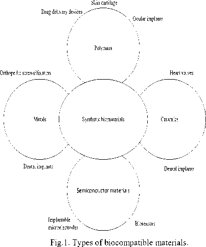
Though there are numerous fields where MEMS system finds its applications. Since we are focusing on biosensing applications, it becomes important to have an idea of biocompatible materials [5]. Before that, it is necessary to understand what biocompatibility is. Biocompatibility is the ability of a material to perform with appropriate host response in a specific situation. Alternatively, it is the ability to be intact with a living system without producing adverse effects. Fig.1. shows different types of biocompatible materials.
-
II. Microcantilever
Microcantilever is a beam of solid material say, silicon, nickel, etc. in the submillimeter range that is kept fixed at one end and allowed to vibrate freely at another end. The vibrations of the cantilever in a particular medium say, air, vacuum or liquid are studied and are then utilized in measuring various parameters involved in the applications. Microcantilevers are the devices that have greater potential as microsensing platform [14]. The features like high mass sensitivity, a high degree of parallelization, easy implementation, non-toxic procedures, better limit of detection, fast response, low fabrication cost, label-free detection etc., makes them an ideal candidate for biosensing applications. The various applications of MEMS are shown in Table 1. [15]. And the different types of biocompatible materials for different applications are shown in Table 2.
Table 1. Various applications of MEMS.
|
Field of application |
MEMS devices |
Purpose |
Advantages |
References |
|
In telecommunication |
Optical MEMS, tunable capacitors, RF MEMS switches, high Q inductor. |
For voltage controlled oscillators, splitters, and couplers, optical attenuators, micro-lenses, displays. |
Improved efficiency of optical assembly and alignment accuracy. |
[6], [7] |
|
In Healthcare |
Pressure sensors, MEMS inertial sensor, capacitive sensors. |
For tonometric blood pressure measurement, surgery, kidney dialysis equipment, respirators, in pacemakers. |
Increased signal output and stability, a sensitivity of 2mV/mm Hg 100 mm Hg and resolution of 0.5 mm Hg. Microfluidics enables reduction of fluid sample size, up to thousands of tests per chip. |
[8], [9] |
|
In automotive industry |
Accelerometer, airbag sensors, break force sensors. |
Collision detection, intelligent tyres. |
3-axis accelerometer consumes less power and is useful for accurate tilt measurement and operating temperature varies from -400C to +1050 C. 3-axis digital gyroscope operating temperature varies from -400 C to +850 C, is used for multiple applications(Pitch, Roll, Yaw) |
[10],[11] |
|
In defense |
Embedded sensors, chemical sensors for soldiers, microactuators. |
Missile guidance, survellience, data storage, identification friend or foe. |
A chemical sensor for soldiers detects chemical agents below harmful thresholds, small lightweight, rugged. MEMS-based Friend or foe identification has 3600 coverage, fast response, low probability of intercept. |
[12],[13] |
Table 2. Biocompatible materials and its area of applications
|
Biocompatible materials |
Area of application |
|
Titanium |
Dental implants, bone implant, pacemaker boxes, surgical instruments |
|
Ni-Ti alloys |
Orthodontics |
|
PIB, EPCO |
Measuring concentration of contaminants in harmful water |
|
Silicone-hydrogel |
Contact lenses |
|
PDMS |
Cerebrospinal fluid monitoring |
Microcantilever works in both static and dynamic modes which are discussed in next section. The cantilever can be used as a sensing device in any environment say, air, vacuum, liquid. In the field of biology, microcantilever can be used for the detection of PSA
(Prostate-Specific Antigen), detection of myoglobin, detecting DNA hybridization, detection of single vaccine virus particle, detection of low-density lipoproteins, detection of Escherichia coli. In the field of chemistry and environmental monitoring, cantilevers are used for the detection of humidity, temperature and heat changes, infrared light and UV radiations, harmful contaminants in water, to estimate changes in fluid pressure, analyte vapors in the gas phase and much more. Fig.2. [16] shows the applications of microcantilever in different fields.
-
III. Generic Operation of Microcantilever
Microcantilever has two modes of operation: static mode and dynamic mode [17]. In static mode, the top surface of the cantilever is coated with antigen sensitive
Sensing Applications of microcantilever

I .ab-on-chip
Ulood glucose Monitoring Detection of DNA and Protein Detection of Hscherichia Coli Detection of Prostate Specific
Antigen< PSA) Detection of low-density lipoproteins To count point mutations
Delection of density / viscosity of different fluids
Detection of humidity Detection of explosives
Fig.2. Sensing applications of microcantilever [16].
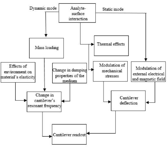
Fig.3. A flowchart depicting cantilever’s mode of operation and transduction principle (Adapted from [19]).
film and the other side of the cantilever is coated with the non-reactive film so as to avoid any hindrance during the antigen-antibody interaction. Alternatively, static mode is sensitive to surface stress [18]. Whereas in dynamic mode both the top and the bottom surface of the cantilever is coated with an active film. Instead of coating both the surfaces of the microcantilever, it is possible to study dynamic behavior (resonant frequency and quality factor) of the cantilever by coating either surface. In dynamic mode, the inertia force is adequate to cause the structure to vibrate. The analyte-antibody interaction causes the change in the total mass which in turn changes the resonant frequency. In static mode, the load is applied slowly as a result of which the inertia force can be ignored. Microcantilever can be made to operate in any medium say, air, water, and vacuum. When we are using the microcantilever in the liquid medium, then cantilever’s dynamic mode of operation is preferred. The reason behind this is that the molecules to be detected do not have attributes that lend themselves to be detected, so dynamic mode is favored over static mode where the frequency of cantilever changes in response to analyte binding. Fig.3. is the flowchart depicting cantilever’s mode of operation [19]. The change in cantilever’s resonant frequency is sensitive to environments’ effects on material’s elasticity, mass loading and damping properties of the medium. And in the case of static mode, the cantilever’s deflection is sensitive to thermal effects, modulation of mechanical stress and external electrical and magnetic field. The most interesting thing about microcantilever sensor is that it can be used to measure the mechanical properties of fluid [20]. By mechanical properties we mean, the fluid’s viscosity, its density. The idea that the cantilever can be used for measuring the rheological properties comes from factuality that the dynamic response of cantilever is contingent on the medium of operation. The conspicuous or determining factors in resonating microcantilevers are resonant frequency and quality factor. So, by tracking the change in resonance frequency and quality factor, we can determine the rheological properties of any kind of fluid. Table 3.shows different deflection detection methods of the microcantilever.
Table 3. Microcantilever deflection detection method.
|
Deflection detection methods |
Working principle |
Advantages |
Disadvantages |
References |
|
Piezoresistive deflection detection method |
Stress is recorded by implanting piezoresistive material near cantilever’s top surface. |
Allows to integrate readout system on chip |
Deflection resolution is small (1nm) |
[21] |
|
Capacitive deflection detection method |
Change in capacitance due to analyte-antibody interaction on the surface of the cantilever is recorded. |
Highly sensitive and provides outright displacement. |
Inefficient while measuring large deflections. |
[22] |
|
Optical deflection detection method |
Deflection of low power laser beam at the surface of the cantilever is recorded using photoelectric position detector. |
Measures deflection in subnanometer range |
Irregular response in liquid cell environment |
[23] |
|
Interferometry deflection detection method |
Interference signal which consists of reference laser beam and the laser beam reflected by cantilever is recorded with the help of photodiode. |
Highly sensitive |
Less sensitive in liquids |
[24] |
-
IV. Different Modes of Vibration
Microcantilever vibrating in any medium exhibits different types of vibrational modes. The nature of these modes depends upon the nature of the force being applied to the cantilever’s surface [25] [26] [27].
-
A. Transverse mode
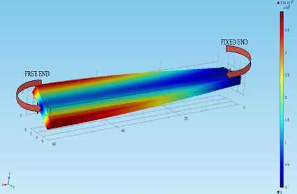
When the microcantilever is subjected to the force which is acting perpendicularly to the cantilever surface and is parallel to the axis at the fixed end, the cantilever is said to be vibrating in the transverse mode. This mode is also termed as the out-of-plane bending mode. Fig.4. represents the transverse mode. It is clear that the cantilever is having zero deflection at fixed end and is exhibiting maximum displacement of 3.37 µm at free end.
The expression for nth order resonant frequency in the transverse mode is given as:
n
Tr
where A is the eigenvalue which can be calculated from 1 + cos ( A n ) cosh ( A n ) = 0 , n is positive integer. The first five eigenvalues calculated are 1.8751, 4.6941, 7.8548, 10.9955, 14.1372.
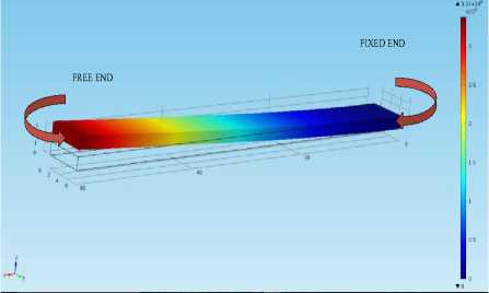
Fig.4. The geometry of a microcantilever having dimensions (60*6*1.5) µm vibrating in the transverse (out-of-plane) direction with undamped natural frequency (5.7762e5Hz).
The eigenvalues are calculated using the formula:
A ,
n (2 i - 1)
-------- for i < 5
-
B. Lateral mode
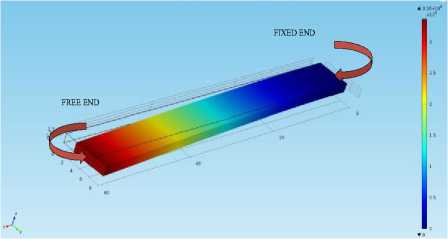
When the force being applied on the surface of the microcantilever is in the direction parallel to the surface of the cantilever and perpendicular to the axis at the fixed end, the cantilever is said to be vibrating in the lateral mode. This mode is also termed as the in-plane flexural mode. Fig.5. represents the lateral mode. It is clear that the displacement is zero at the fixed end and is having maximum value of 3.36 µm at the free end.
и depends upon the chosen material
I is the polar moment of inertia given by:
I p
tw 3 + wt 3
^ is the damping coefficient given by:
Fig.5. The geometry of a microcantilever having dimensions (60*6*1.5) µm vibrating in the lateral (in-plane) direction with undamped natural frequency (2.2871e6Hz).
§ = 114
t
w 192^f 1 . ,
-_XI "5tanh
П n = 1 \ n

The expression for nth order resonant frequency of microcantilever vibrating in the lateral mode is given as:
fn
La
wX EE
4nL2pp c
The eigenvalues ( X ) calculated above are same for inplane mode.
C. Torsional mode
When the nature of the cantilever vibration is such that its one edge of the free end is vibrating in the y-direction and another edge in –y direction, then the cantilever is said to be vibrating in the torsional mode. Fig.6. represents torsional mode. It is clear from the figure that at the fixed end the displacement is zero and at the free end, it is having maximum deflection of 3.91 µm.
Table 4. Symbols used in above equations
|
Symbol |
Meaning |
|
E |
young’s modulus |
|
L,w,t |
length, width, and thickness of the beam. |
|
X . |
The eigenvalue of nth mode. |
|
P c |
beam density. |
|
G |
shear modulus. |
|
I p |
polar moment of inertia. |
|
^ |
damping coefficient |
|
и |
Poisson ratio. |
V. Dimensions and MATERIAL of MICROCANTILEVER
The material chosen for the cantilever is silicon because its Young Modulus is small as compared to other materials [28]. Young Modulus basically indicates the elasticity of the material. The lower value of elasticity indicates higher sensitivity. For this reason, silicon is preferred over other materials.
Table 5. Mechanical Properties of Silicon material.
|
Property |
Value |
|
Young’s Modulus |
131e9Pa |
|
Poisson’s ratio |
0.27 |
|
Density |
2330kg/m3 |
Fig.6. Geometry of microcantilever having dimensions (60*6*1.5) µm vibrating in the torsional mode with undamped natural frequency (1.0169e7Hz).
The expression for nth order resonant frequency of microcantilever vibrating in the torsional mode is given as:
„ (2 n-1) git
J To 4 L p i plp
where G is given by:
G =
E
2 ( 1 + и )
Table 6. Dimensions of microcantilever (Adapted from [29] ).
|
Dimension |
Value |
|
Length |
60 ц т |
|
Width |
6 ^ m |
|
thickness |
1.5 ц т |
VI. Overview of Application of Microcantilever in Liquid Medium
The idea that the cantilever can act as an ideal candidate for measuring rheological properties of fluid [30] [31] [32] [33] originate from the fact that the cantilever’s dynamic response is contingent on the medium of operation. The dynamic response of the cantilever can be viewed in the matter of resonant frequency and quality factor.
-
A. Selection of mode of operation
As discussed earlier, for sensing applications, microcantilever can be operated either in static or dynamic mode. Static mode is responsive to stress induced on the cantilever surface and the dynamic mode is responsive to change in mass of microcantilever. During analyte-antibody interaction, molecular constituents do not provide useful information that is necessary for detection. For this reason, in liquid phase sensing applications, mass sensitive sensors are used. Thus, when microcantilever operates in a dynamic mode, their resonant frequency changes in response to analyte binding and the properties of the fluid are measured accordingly.
-
B. Selection of mode of vibration
As discussed earlier, microcantilever mainly has three modes of vibration, namely, transverse, lateral and torsional. When our operating medium is air or vacuum, in that case, transverse mode of vibration is preferred. But as we change our operating medium from air to liquid, then working with transverse mode becomes difficult or quite inefficient. The performance of the microcantilever degrades by considerable damping. Because when the cantilever is immersed in a fluid, it suffers resistance being offered by fluid [34]. Consequently, both resonant frequency and the Quality factor of the beam decreases drastically when the operating medium i.e. air is replaced by water.
Table 7. Comparison of vibrational mode for liquid phase sensing application.
|
Transverse |
Lateral |
|
50% shift in resonant frequency. |
5-10% shift in resonant frequency. |
|
The Quality factor is not good. |
The Quality factor is 5 times larger. |
|
Gravimetric sensitivity is poor. |
Gravimetric sensitivity is improved by when immersed in water. |
|
Limit of detection is commendable. |
Limit of detection is around 100ppb compared to the out-of-plane. |
|
Flexural rigidity is small. |
Flexural rigidity | b[ | is I h2) greater than the transverse flexural mode. |
L.A. Beardslee et al. [35] investigated a cantilever which was 400µm long, 90µm wide and 20µm thick for both lateral (in-plane) and transverse (out-of-plane) vibrations. The response of the cantilever operated in vacuum came to be 154.6kHz (Q=680) and that in the water came to be 96.1kHz (Q=20) i.e., shifted by 38% when operating medium air is replaced by water. Whereas the in-plane vibrating cantilever shifted from 636.7kHz to 596.0kHz i.e., shifted by 7% only. It is thus concluded that the in-plane mode is least affected by fluid damping and mass loading caused by surrounding fluid. Hence concluded that lateral flexural mode is preferred over transverse flexural mode for sensing applications in the liquid medium. The increased resonant frequency and decreased the effective mass of beam in the case of lateral mode results in increased mass sensitivity which in turn leads to the lower limit of detection in liquid phase biosensing.
Table 7.shows the comparative analysis of vibrational mode for liquid phase chemical sensing applications.
-
C. Geometrical consideration for design of liquid phase sensor
At the micro-scale, the cantilever’s vibrations instead of depending only on the microstructure’s properties and surrounding medium properties also depend on the structure’s geometry. The dynamic behavior of cantilever is investigated in terms of beam geometry and medium property.
Following are the design considerations for liquid phase sensor [36] [37] [38]:
-
1. Shorter, wider, thicker microcantilevers are best for biosensing applications as it yields highest Q-factor while vibrating in the in-plane mode in liquid [39].Q-factor increases with increase in device thickness.
-
2. The beam cross sectional area should be assumed uniform all over the beam length.
-
3. The beam length should greatly exceed the width of the microcantilever beam.
-
4. The amplitude of vibration should be considered considerably smaller than any length scale in geometry.
-
D. Fluid-structure interaction of microcantilever
There are several flexible structures say, microcantilever, micropumps, microplates, microvalves, micro flow sensors, microviscosity sensors that undergo deformation through several means such as fluid pressure, phase change, electrostatic force, magnetostatic force, friction. All these microfluidic devices involve microfluidic structure interaction [40].
While analyzing the cantilever operating in the viscous medium, our first task is to study the effect of hydrodynamic force on the microcantilever vibrations [41] [42]. Hydrodynamic forces are the forces that the fluid exerts onto the body of the structure e.g. Drag and lift force.
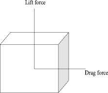
Fig.7. Schematic of lift and drag force components when fluid flow passes a body.
When the structure is allowed to settle in a liquid medium, the fluid flow endeavors a force on structure’s surface as shown in fig.7. The component of force that is acting in the direction parallel to the fluid flow direction is called drag force and the component of force that is acting in the direction perpendicular to the fluid direction is labeled as lift force [43]. The hydrodynamic force shown in fig. 8 is the resultant of the pressure (lift) force and the shear (drag) force.
F ( x , t ) = - g 1
dv(x, t) d2v(x, t)
dx g2 dt2
In the frequency domain, (4) is expressed as:
Fhydrodynamic F shear + Fpressure F fluid ^ j ” g \ (x , ” ) ” g 2( x , ” ) ] y ( x , ” ) (12)
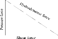
Fig.8. The hydrodynamic force acting on cantilever beam; shear and pressure force.
to = frequency of vibration, y= microcantilever deflection.
g is given as:
g 1 — M L ( 2 n fA b l - + b 2 | | w 1 2
E. Equations governing fluid-structure interaction of microcantilever
When the cantilever is settled in a liquid medium, the motion of the cantilever suffers resistance being offered by the fluid. The dynamic behavior (resonant frequency and quality factor) of the cantilever that depends on the properties of the medium in which they are operating are calculated. This enables us to measure the mechanical properties of different types of fluid.
The Euler-Bernoulli equation of motion before the application of an external force is given as:
d 4 y(x , t) d 2 y(x , t)
EI ( 4 , ) + P b A ( — 0 (8)
d x a t
g is given as:
npf wM, — -E-l--
L 4
g 2 — ML
p f = fluid density.
w= width of the cantilever.
a + a^ — w J
a 1 = 1.0553, a 2 = 3.7997, b 1 =3.8018, b 2 =2.7364 are “Maali’s Parameters” [45].
Where, bh3
I — (in case of transverse mode)
b 3 h
I — "y^" (in case of lateral mode)
The boundary layer thickness or skin depth can be expressed as:
e_ I 2Ц
—
V Pf (2П11 )
In the presence of external force, the equation of motion is modified as:
34y(x,t) d2y(x,t) / x ,
EI + Pb A у — F y ( x ) e ” (9)
dx d t
When microcantilever is allowed to vibrate in the viscous medium, then an additional force is exerted on the surface of the cantilever. Consequently, the beam equation is written as:
d 4 y(x , t) d 2 y(x , t) , у у
EI + P b A — F y ( x ) e ” + F ( x , t ) (10)
о x о t
This additional hydrodynamic force, F(x,t) [44] is written as:
The amount of fluid excited by the vibrating beam is directly proportional to the skin depth [46]. The resonant frequency [47] and quality factor incorporating the effect of hydrodynamic force are expressed as:


2 Q t 2 otal
„ (ьЛ( ПТЛ
fo,vacuum — 0-1615 I T2- I , ~
V L JU Pb J
where f o , vacuum =undamped resonance frequency in the vacuum.
m= mass of the cantilever.
f = resonant frequency.
b, L= beam width and length respectively.
The quality factor of cantilever immersed in a liquid comprehends fluid damping as well as internal damping effects.
Thus the quality factor can be expressed as the contribution of these two main components:
flow the wavelength of microcantilever’s vibration greatly exceeds the width of the cantilever [49]. Hence the fluid is considered incompressible.
Assuming the velocity gradient of fluid and beam to be small, the fluid’s equation of motion is given as [50]:
d U <—7 7-! 2
Pl — —-V P + nV u (20)
Qtotal
—--1--
Q int Qfluid
Q is the internal quality factor of the microstructure and Q is the quality factor contributed by the fluid.
When the cantilever vibrates in out-of-plane mode, fluid-induced losses tends to dominate. So it is possible to replace fluid-induced losses. Consequently, Q is approximately equal toQ . The fluid dependent quality factor, using results of Sader is given as [48]:
Where Pi^u is fluid’s inertial forces and n V 2 u is the fluid’s viscous forces.
The Renolds number is defined as the ratio of fluid’s inertial forces to the fluid’s viscous forces and is expressed as:
Re — Pw -
4n
fluid
2 n fo , vacuum

Lg 1
m
Higher the value of Renolds number, lower will be the viscosity of the fluid and vice-versa.
The analytical expressions of viscosity and density that depends on Maali’s parameters, the resonant frequency in the vacuum, the dimensions, the density of the cantilever, £ and eigenfrequency are given as [51]:
In order to model the fluid, the incompressible form of Navier-stokes’ equation is used. This is because in the
n —
2 abh p
vacuum
— f l ) + 2 £ a 2 f vacuum
—
vacuum
—
f„ ) 2 + 4 £f [ aЖ™
-Ub-laK\U 2 -f2 'll
2 1 12 vacuum o I
fo ( b 1 a 2 — a 1 b 2 )[ ( a 2 b 1 — 2 ab 2 ) ( f vacuum
2 22
o 2 vacuum 2
vacuum
—
f 2 2 + 4 5 f 2 [ a 2 5 f 2
o vacuum I 2^ J vacuum
2 11
21 12 vacuum o
Pf —
2 h p rt f a 1 ( a 2 b — a b 2 )
( a b — 2 a b 2 ) ( f„
— f 0 2 ) — 2 £ a 22 f v a« um
+ a

-f 22+Af2 [ 111 (23)
o vacuum I 2 J vacuum 2 1 12 vacuum o
where the damping ratio in the fluid is given as:
g 1 o
4 n fvaCuummL J1 + ( g 2 ( f ) ) ) / ( m L )
And the eigenfrequency ( f ) in the fluid is given as:
f vacuum
V1 + ( g2 ( fo ) / ( mL ))
Table 8. Symbols used in above equations.
|
Symbol |
Meaning |
|
g 1 ,g 2 |
Fluid coefficients. |
|
f vacuum |
Undamped resonant frequency. |
|
Re |
Renolds number. |
|
fo |
Eigenfrequency in the fluid. |
|
P f |
Fluid density. |
|
n |
Fluid viscosity. |
|
5 |
Damping coefficient |
|
mL |
Mass of the cantilever. |
|
a 1 ,a 2 ,b 1 ,b 2 |
Maali’s parameters. |
|
EI |
Flexural rigidity. |
|
Q fluid |
Quality factor due to the fluid. |
|
5 |
Boundary layer thickness. |
|
P |
Pressure at a particular point in the fluid. |
|
u |
Velocity at a particular point in the fluid. |
-
VII. Microcantilever in Biomems Applications
As discussed earlier, microcantilever finds its application in different fields [52] [53] [54] [55] [56] [57]. Some of the biosensing applications are discussed below:
-
A. MEMS pressure sensor
Measurement of pressure in various organs say heart, urinary bladder, eye etc. is very important to get an indication of patient health. In Ref. [58] embedded system has been designed to monitor the health status of the patient. Lawrence Yu et al [59] have discussed the fully implantable pressure sensor for pressure measurement without having any infection risks posed by catheters or wires. These fully implantable MEMS pressure sensors can also be used for IOP monitoring of Glaucoma patient. CardioMEMS manufactured a heart failure monitoring system that utilizes HF pressure sensor that is having attractive features [60]. It does not require a battery (externally powered), no lead and is smaller in size (3.5*2*15mm) say, millimeters. Michael A. Fonseca [61] have designed a flexible wireless passive pressure sensor that is capable of measuring pulse pressures ranging between 12-37mmHg and mean pressures ranging from 70-120mmHg in animals.
-
B . Cantilever biosensors for magnetic detection of virus
In the case of a patient who is suffering from AIDS, it is very important to monitor the sequence of HIV (Human Immunodeficiency Virus) so as to stop the infection from spreading and improving the living condition and life expectancy of the patient. Though monitoring the sequence of HIV is not an easy task. It requires highly expensive and time-consuming procedures. With a view of the prevailing situation, Microcantilever came into the picture being highly sensitive, smaller in size, cheap, portable, robust. It helped doctors to monitor the progression of HIV. In Ref. [62], cantilever (500*100*0.9mm) for detection of magnetic nanoparticles have been discussed which exhibited static deflection as low as 2e-3nm.
-
C . Cantilever biosensors for detection of specific protein
The cantilever can be used for detection of specific protein. For example, in the case of the tumor where normal cells are stimulated to produce angiogenesis (the development of new blood vessels) signaling molecules. The resulting new blood vessels allow cancer cells to attack nearby tissues and thereby forming new colonies of cancerous cells called metastases. Yu et al. [63] have demonstrated that the angiopoietin-1 and 2 promotes or inhibits tumor angiogenesis. So for the detection of Angiopoietin, the microcantilever is chosen. Carlo et al [64], designed cantilever (1200*800*7mm) for which the measured frequency shifts and relative frequency changes for Ang-1 at 25 µg/ml came to be (–1.52 ±0.94)102.
-
D . Cantilever for measuring glucose level in blood
The determining factor to identify if a person is suffering from diabetes is glucose level. There are available different laboratory diagnostic equipment for monitoring the glucose level that employs collection and analysis of blood which causes pain and tension to the patients. The alternative to these procedures is using a non-invasive technique for the measuring glucose level in blood. Paper [65] presents a cantilever (1000*100*10и m) that is coated with selective antigen (probe molecule) anayte-antibody interaction is studied. When the antigen present in the saliva comes in contact with the surface of the cantilever, the glucose level can be estimated by tracking the change in resonance frequency.
-
E . MEMS inertial sensor
Nowadays MEMS Accelerometers are used for biosensing application in defibrillators and pacemakers. In case a person’s heart beats unusually very fast, in that situation, there are chances of cardiac arrest. The function of defibrillators is to provide electrical shocks to allow the normal heart beat. The function of a pacemaker is to maintain the heart beat under abnormal conditions. Endevco Corporation modeled 40366 accelerometers [66] that are considered ideal for implantable medical device applications. The implantable devices include rate responsive heart pacemakers and defibrillators. This accelerometer fulfills all the requirements desired in medical applications i.e. highly reliable, repeatable, smaller package size.
-
VIII. Conclusion
Cantilever explores the wide area of applications. The cantilever-based sensor platform proved to be the best option over available time consuming, expensive analytical instruments. Microcantilever is the first successful mass production product for inertial applications. It has got very rich understanding and its theory is well developed. It can be produced in semiconductor fabrication lab. It is possible to propose new innovative structure for such devices. It is hoped that microcantilever based devices can be integrated with other biomedical devices for monitoring and measuring bio-interest quantities in big way, in coming future. Cantilever’s ease of preparation, being independent of the environmental changes gained the attention of researchers. Microcantilevers have greater potential as microsensing platform, have high mass sensitivity, better limit of detection, low fabrication cost. Microcantilever finds huge opportunity in medical and biotech applications due to the availability of compatible materials and sizes and being capable of electronics integration. In addition to different areas of application discussed above, cantilever also finds its application in cell culture, filtration products, materials characterizations, chip cooling, microphones, gas flow metering. Though a large number of bioMEMS devices are already available in the market but the research is still going on for designing more promising devices. Despite ample advantages, there are certain challenges in MEMS for medical applications like packaging where MEMS chip requires electrical connect, mechanical stress management, Application Specific
Integrated Circuit (ASIC), small form factor. Also, for both MEMS function and biocompatibility, hermeticity is required to determine productiveness of the seal in MEMS packages. For sterilization, there are limitations on certain materials like Ethylene oxide which can be absorbed by plastic, gamma, e-beam which cause damage to electronics and few plastics. Besides this, MEMS devices still have a huge opportunity in medical and biotech applications.
References Microcantilever: an efficient tool for biosensing applications
- Srinivasa Rao Karumuri1, K.Girija Sravani, S. Durga Sailaja, J.Vijay Sekhar, Y.Srinivas, and Ramendu Bhattacharjee, “Micro-Electro-Mechanical-Systems (MEMS) Technology”, in Archives of Applied Science Research, pp.307-314,2012.
- Turner A.P.F., “Current Trends in Biosensor Research and Development”, Sensors Actuators, Vol. 17, pp. 433-450, 1989.
- Christopher J. Pipe, Gareth H. McKinley, “Microfluidic rheometry”, Mechanics Research Communications, Vol. 36, pp. 110-120, 2009.
- Y. Li, P. Denny, C.-M. Ho, C. Montemagno, W. Shi, “The Oral Fluid MEMS/NEMS Chip: Diagnostic and Translational Applications”, Advances in Dental Research, June 2005.
- Mihov, B.Katerska, “Some biocompatible materials used in medical practice”, Trakia Journal of sciences, Vol.2, pp. 119-125,2010.
- El-Fatatry A., “Optical Microsystems, Mechno-optical-Electro-Mechanical Systems-MOEMS”, NATO , Science and Technology Organization,2004.
- De Dobbelaere P, Falta K, Gloeckner S, Patra S., “ Digital MEMS for optical switching”, IEEE Communication magazine, 40(3), pp. 88-95, March 2002.
- Ziaie B. and Najafi K., Biomed. Microdev. Vol. 3, pp. 285-292, 2001.
- Allisa M. Fitzgerald, “MEMS for Medical Applications”, IEEE-EMBS, 17 November 2010.
- “MEMS sensors for automotive applications”, HIS Market Tracker Automotive MEMS H1, 2014.
- Masako Tanaka, “An industrial and applied review of new MEMS devices features”, Microelectronic engineering, Vol. 84, pp. 1341-1344, August 2007.
- Keith W. Brendley, Randall Steeb, “Military Applications of Microelectromechanical systems”, National defence research institute.
- Courtney E. Howard, “MEMS and nanotechnology continue to solve challenges in military and defense applications”, Military and aerospace, June 5, 2008.
- Anuj Kumar Goel, Dr. Kuldip Kumar, “Design and simulation of microcantilevers for sensing applications”, International journal of applied engineering research, pp. 501-503, 2016.
- M. Parameswaran, H. P. Baltes, L. Ristic, A. C. Dhaded, and A. M. Robinson, Sensors and Actuators, Vol.3, pp. 289-307, 1989.
- Vashist, “A Review of microcantilevers for sensing applications”, Journal of Nanotechnology, Vol.3, 2007.
- Manjula sahu, “Simulation of static mode and dynamic mode of microcantilever structures”, International journal of advance engineering and research development, vol. 3, March 2016.
- M. Calleja, J. Tamayo, A. Johnsson, P. Rasmussen, L. Lechuga, A. Boisen, “Polymeric Cantilever arrays for biosensing applications”, Sens Lett., 2004.
- Michael Sepaniak Panos Datskos, Nickolay Lavrik Christopher Tipple, “Microcantilever Transducers: A New Approach in Sensor Technology”, in Analytical chemistry, November 2002.
- Yan F, Chan HLW, “Analytical model of piezoelectric cantilever as rheological sensor”, Phys B, 2011.
- Mo Yang, Xuan Zhang, Kambiz Vafai, Cengiz S Ozkan, “High sensitivity piezoresistive cantilever design and optimization for analyte-receptor binding”, J. Micromech. Microeng. , Vol. 13, pp. 864-72, August 2003.
- Blanc, N. Brugger, J., Rooij, N.F.D., Durig, U., “Scanning Force microscopy in the dynamic mode using microfabricated capacitive sensors”, J. Vac. Science and Technology. B, Vol. 2, pp. 901-05, 1996.
- Meyer, G. & Amer, N.M, “Novel optical approach to atomic force microscopy”, Applied Physics, Lett. , Vol. 53, pp. 1045-47, 1988.
- Erlandsson, R. McClelland, G.M., Mate, C.M. & Chiang, S., “Atomic force microscopy using optical interferometry”, J. Vac. Sci. Technol. , Vol. 6, pp. 266-70, 1988.
- Blake N.Johnson, Raj Mutharasan, “Biosensing using dynamic- mode cantilever sensors: A review”, Biosensors and Bioelectronics, Vol. 32, pp. 1-18, 2012.
- Karen M. Goeders, Jonathan S. Colton, Lawrence A. Bottemley, “Microcantilevers: Sensing Chemical Interactions via Mechanical Motion”, Chem. Rev., Vol. 108, pp. 522-542, 2008.
- R.D. Blevins, “Formulas for Natural Frequency and Mode Shape”, Von Nostrand Reinhold Company, New York, 1979.
- John Wiley, “Microcantilever sensors”, chemical sensors and biosensors: fundamentals and applications, 2012.
- Onur Cakmak, Caglar Elbuken, Erhan Ermek, Ibrahim Baris, Hakan Urey, “Microcantilever based disposable viscosity sensor for serum and blood plasma measurements”, Methods, Vol. 63, pp. 225-232, 2013.
- Boskovic, S.; Chon, J.W.M.; Mulvaney, P.; Sader, J.E., “Rheological measurements using microcantilevers, Journal of Rheology, Vol. 46, pp. 891-899, 2002.
- Hennemeyer, M.; Burghardt, S.; Stark, R.W., “Cantilever micro-rheometer for the characterization of sugar solutions”, Sensors, Vol. 8, pp. 10-22, 2008.
- I. Dufour, A. Maali, Y. Amarouchene, C. Ayela, B. Caillard, A. Darwiche, D. Saya, “The Microcantilever: a versatile tool for measuring the rheological properties of Complex fluids”, Journal of Sensors, 2012.
- Cox, R.; Zhang, J.; L.A. Brand, “Damping and mass sensitivity of laterally vibrating resonant microcantilevers in viscous liquid media”, In Proceedings of the 2012 IEEE International Joint Conference on Frequency Control and the European Frequency and time forum, San Francisco, USA, pp. 1-6, May 2011.
- N. Belmiloud, I. Dufour, A. Colin, L. Nicu, “Rheological behavior probed by vibrating microcantilevers”, Applied Physics, Vol. 92, pp. 041907-41909,2008.
- L.A. Beardslee, F.Josse, S.M. Heinrich, I. Dufour, O. Brand, “Geometrical considerations for the design of liquid-phase bio-chemical sensors using a cantilever’s fundamental in-plane mode”, in Sensors and Actuators B, Vol. 164, pp.7-14, 2012.
- Naeli, K. and O. Brand, “Dimensional Considerations in Achieving Large Quality Factors for Resonant Silicon Cantilevers”, in Air. Journal of Applied Physics, Vol. 1, pp. 014908, 2009.
- L.A. Beardslee, .M. Addous, K.S. Demirci, O. Brand, F.Josse, “Geometrical optimization of resonant cantilevers vibrating in in-plane flexural mode”, IEEE Sensors Conference, 2010.
- Seo, J.H., O. Brand, “High Q-factor in-plane mode resonant microsensor platform for gaseous/liquid environment”, Journal of Microelectromechanical systems, Vol. 2, pp. 483-493, 2008.
- Russell Cox, Fabein Josse, Stephen M. Heinrich, Oliver Brand, Isabelle Dufour, “Characteristics of laterally vibrating resonant microcantilevers in viscous liquid media”, Journal of Applied Physics, Vol. 111, 2012.
- G.K. Batchelor, “An Introduction to Fluid Dynamics”, Cambridge University Press, Cambridge, Vol. 169, 1967.
- I. Dufour, E. Lemaire, B. Caillard, H. Debeda, C. Lucat, S.M. Heinrich, O. Brand, “Effect of hydrodynamic force on microcantilever vibrations: Application to liquid-phase chemical sensing”, Sensors and Actuators B: Chemical, Vol. 192, pp. 664-672, 2014.
- S. Basak, A. Raman, “Hydrodynamic loading of microcantilevers vibrating in viscous fluids”, Journal of Applied Physics, Vol. 99, 2006.
- L.D. Landau, E.M. Lifshitz, “Fluid Mechanics”, Pergamon Press, London, 1959.
- C. Vancura, I. Dufour, S.M. Heinrich, F. Josse, Sensors and Actuators A- Physical, Vol. 141, pp. 43-51, 2008.
- A. Maali, C. Hurth, R. Boisgard, C. Jai, T. Cohen-Bouchacina, J.P. Aime. “Hydrodynamics of oscillating atomic force microscopy cantilevers in viscous medium”, Journal of Applied Physics, 97(7), 2005.
- U. Sampath, S.M. Heinrich, F. Josse, D. Rebiere, “Study viscoelastic effect on the frequency shift of microcantilever chemical sensors”, IEEE Trans.Vol. 11, 2006.
- I. Dufour, “Strong-axis bending mode vibrations for resonant cantilever biochemical sensors in gas or liquid phase”, Proceedings of the 2004 IEEE International, Montreal, August 2004.
- J.E Sader, “Frequency response of cantilever beams immersed in viscous fluids with application to the atomic force microscope”, Journal of Applied Physics, Vol. 87, 2000.
- J.Sader, J.Appl. Physics, 84,1998
- S.M. Heinrich, R. Maharajan, L. Beardslee, O. Brand, I. Dufour and F. Josse, in Proceedings of the International Workshop on Nanomechanical cantilever Sensors, Banff, Canada, pp. 26-28, May 2010.
- M. Youssry, N. Belmiloud, B. Caillard, C. Ayela, C. Pellet, I. Dufour, “ A straightforward determination of fluid viscosity and density using microcantilevers: From experimental data to analytical expressions”, Sensors and Actuators A: Physical, Vol. 172,40-46,2011.
- Li, X. et al., “Integrated MEMS/NEMS Resonant Cantilevers for Ultrasensitive Biological Detection”, Journal of sensors, 2009.
- Urey, H., et al. “MEMS Biosensor for Parallel and Highly sensitive and Specific Detection of Hepatitis”, in 24th IEEE MEMS Conference, 2011.
- Seo, J.H., “Silicon- Based Resonant Microsensor Platform for Chemical and Biological Applications”, in Electrical and Computer Engineering, pp. 192, 2007.
- D. Lange, C. Hagleitner, A. Hierlemann, O. Brand, H. Baltes, “Complementary metal oxide semiconductor cantilever arrays on a single chip: mass sensitive detection of volatile organic compounds”, Analytical Chemistry, Vol. 13, pp. 3084-3095, 2002.
- B. Jakoby, M. Scherer, M. Buskies, and H. Eisenschmid, “An automotive engine oil viscosity sensor”, IEEE Sensors Journal, Vol. 3, pp. 52-568, 2008.
- P.Sangeetha, Dr. A.Vimala Juliet, “Simulation and analysis of microcantilever sensor for enhanced biosensing of disease causing pathogens”, IJEDR conference proceeding, 2014.
- Shriram K Vasudevan, Sivaraman R, Subashri V, Murali N, “Design and development of an embedded system for monitoring the health status of patient”, I.J. Intelligent systems and applications, pp. 64-71, 2013.
- Lawrence Yu, Brian J. Kim, Ellis Meng, “Chronically implanted pressure sensors: Challenges and State of the Field”, Sensors, 14(11), pp. 20620-20644, November 2014.
- Jay S. Yadav, “CardioMEMS Champion Heart Failure Monitoring System”, December 2011.
- Michael A. Fonseca, Mark G. Allen , Jason Kroh and Jason White, “Flexible Wireless Passive Pressure Sensors for Biomedical Applications”, Solid-State Sensors, Actuators, and Microsystems Workshop Hilton Head Island, South Carolina, June 4-8, 2006.
- Joe Bailey, “Cantilever Biosensors: Towards the Magnetic Detection of Viruses”, University College, London, December 2015 (Ph.D. Thesis).
- Q. Yu, Future Oncol, Vol. 1, pp. 475-484, 2005.
- Carlo Ricciardi, Giancarlo Canavese, Ricardo Castagna, Ivan Ferrante, Alessandro Ricci, Lucia Napione, “Integration of microfluidic and cantilever technology for biosensing application in liquid environment”, Biosensors and Bioelectronics, Vol. 26, 1565-1570, 15 December 2010.
- G. V. Sunil Kumar , T. Milinda Purna, Dr. V. R. Anitha, “NonInvasive Technique for the Measurement of Glucose Levels in Blood using MEMS Devices”, IJETAE, Vol. 4, August 2014.
- Sensors and transducers e-digest, Vol. 9, Issue 5, May 2007.
