Miniaturized planar monopole UWB antenna with integrated RFID/GPS/GSM/WLAN bands using capactively loaded loop resonator (CLLRs)
")
Author: Mubarak Sani Ellis, Ahmed Abdul-Rahman, Jerry John Kponyo
Journal: International Journal of Wireless and Microwave Technologies @ijwmt
Article in issue: 6 Vol.8, 2018.
Free access
A miniaturized multiband planar monopole Ultrawideband (UWB) antenna is presented. The penta-band antenna is comprised of a: 3.1 – 10.6 GHz UWB band, 2.4 WLAN band, 1.8 GHz GSM band, 1.3 GHz GPS and a 0.95 GHz RFID band. The proposed UWB band is realized by using half of a conventional rectangular radiator size while the other half is used to realize the other bands by employing quarter wavelength U and G shaped strips called folded CLLRs (capacitively loaded loop resonators). The designed penta-band antenna has an overall size of 25 x 30 mm2. The measured and simulated results of the fabricated prototype are compared and satisfactory results are achieved.
Microstrip, Ultrawideband, CLLR, quarter-wavelength, RFID, miniaturize, penta-band antenna
Short address: https://sciup.org/15016950
IDR: 15016950 | DOI: 10.5815/ijwmt.2018.06.03
Text of the scientific article Miniaturized planar monopole UWB antenna with integrated RFID/GPS/GSM/WLAN bands using capactively loaded loop resonator (CLLRs)
In this work, a new approach is used to achieve a penta-band UWB antenna. Here, a UWB antenna with a rectangular monopole is used as the base antenna. The rectangular radiator of the UWB is vertically cut into almost half the size to still maintain a bandwidth from 3.1 – 10.6 GHz, resulting in a miniaturized design. With the space created on the monopole, the other bands are created by attaching U and G shaped resonant strips (CLLRs) ‘hanging’ from a non-resonant horizontal strip attached to the top of the miniaturized rectangular radiator. In [7] - [9], the novelty of their proposed techniques were that the resonant strips can be added to the base structure of an existing UWB antenna to achieve an extra resonant point without affecting the UWB behavior. In the proposed antenna, a new technique is introduced which does not involve the base structure of the UWB antenna and provides a new and easier approach to achieve many extra bands than that suggested in [7] - [9]. Additionally, it also provides a more miniaturized antenna. To the best of our knowledge, the proposed antenna is the only UWB with four extra integrated bands.
-
2. Antenna Design
-
3. UWB Miniaturization
The proposed antenna is etched on an FR4 substrate with relative permittivity ɛ r = 4.4 with a thickness of 1.6 mm. The overall size is 25 x 30 mm2. The UWB monopole and the other resonant elements are etched on top of the substrate and the ground plane is etched on the bottom. The design of the antenna begins with a conventional UWB antenna made up of a radiating monopole attached to the microstrip line to achieve a 3.1 – 10.6 GHz UWB band. The proposed antenna is shown in Figure 1.
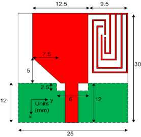
Fig.1. Geometry of the proposed antenna
The evolution of the antenna is shown in Fig. 2. Fig. 2(a) shows a conventional UWB antenna comprising of a rectangular monopole and the microstrip feedline on one side and the ground plane on the other side. In Fig. 2(b), a portion of the radiator is cut without affecting the impedance bandwidth of the UWB antenna, resulting in a miniaturized design. The theory behind this is that, the lower frequency limitation of the UWB antenna is dependent on the longest current path of the monopole radiator. However, we noticed that this path is mainly dependent on the horizontal edge (length) of the radiator and the vertical edge (width) has very little influence on the lower end bandwidth. Therefore, by reducing the size (width) of the radiator, the impedance bandwidth is still maintained, resulting in a miniaturized antenna. This phenomenon can be verified in Fig. 3 showing that the impedance bandwidths of the antennas with and without the cut remain the same.
SUS
(a)
(d)
(b)
(c)
(d)
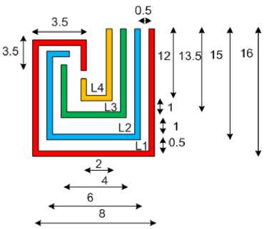
Fig.2. Evolution of the proposed antenna; (a) conventional UWB antenna (b) miniaturized UWB antenna (c) miniaturized UWB with nonresonant horizontal strip (hanger) (d) miniaturized UWB with integrated wlan, gps, gsm, and rfid CLLRs elements (e) geometry of CLLRs (units: mm)
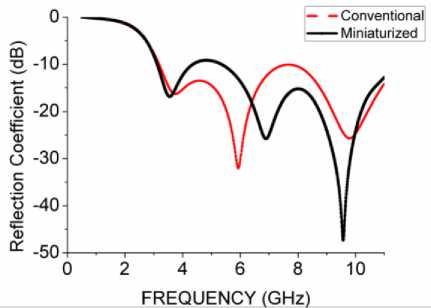
Fig.3. Combined return loss graph of antennas in Fig. 2(a) and Fig. 2(b) (conventional and miniaturized antennas)
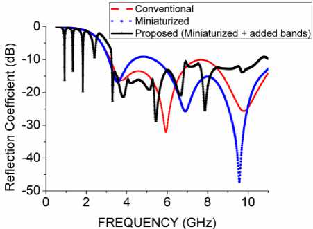
Fig.4. Combined S 11 graphs of antennas in Figs. 2(a), 2(b) and 2(d) showing the effect of each stage
Table I. Calculated and Optimized Strip Lengths for Various Resonant Frequencies Integrated with the UWB Band
|
Frequency ( GHz ) |
Total Length ( mm ) |
Initial ( calculated ) |
Final ( Optimized ) |
|
0.95 |
L1 |
48.0 |
45.0 |
|
1.3 |
L2 |
35.1 |
35.0 |
|
1.8 |
L3 |
25.4 |
25.0 |
|
2.4 |
L4 |
19.0 |
14.5 |
-
4. Integrated Multiband Design
-
5. Results and Discussion
The printed antenna is fabricated and then measured with an Agilent N5230A PNA-L and a SATIMO measurement system. The picture of the fabricated prototype is shown in Fig. 5. The simulated and measured reflection coefficients are plotted in Fig. 6. The results show that the proposed antenna can cover the UWB band from 3.1 – 10.6 GHz with four additional distinct bands for VSWR ≤ 2 (or S 11 ≤ 9.5 dB). The measured results and simulated results agree well. The discrepancy is due to the attached SMA connector and fabrication imperfections, especially with the narrow bands. Additionally, the close proximity of the resonant elements causes a little problem with achieving the exact bandwidth for each resonant point. This is one of the main challenges of the proposed method. Nonetheless, satisfactory results were achieved.
The multiband band design is integrated to the miniaturized UWB antenna discussed in section 3. Here, the space created on the radiator, due to the cut, is used to accommodate the multiband resonant elements. To realize the multiband performance, as shown in Fig. 2(d), additional resonant strips (CLLRs) are placed at the space created from the cut. Firstly, a horizontal non-resonant element is attached to the top of the miniaturized
UWB antenna to serve as a “hanger” for the resonant elements as shown in Fig. 2(c). For a desired resonant frequency, the total length of each element is given by L total ≈ λ g / 4 where λ g is given by λ g ≈ λ o / (ϵ r + 1). Using these values, the length of each strip can be obtained and further optimized to obtain a desired value. The initial and final values are shown in Table I.
The effect of adding the resonant strips is also shown in Fig. 4.
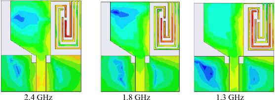
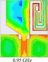
The E-field distribution of the proposed antenna is shown in Fig. 7. At each distinct resonant frequency, it can be noticed that one CLLR element is resonant. At this frequency, the CLLR element acts like a quarter wave monopole, following the equation in Section 4.
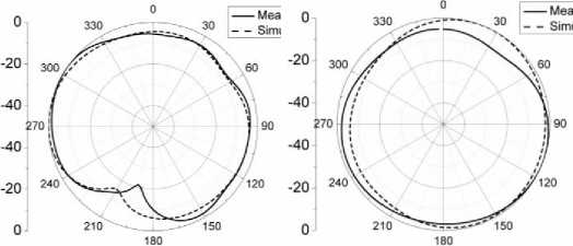
Figure 8 shows the radiation patterns at different frequencies. The E-plane ( xoy , θ = -90) and H-plane ( yoz , ϕ = 90) are shown on the left and right columns respectively. It can be noticed that a monopole-like radiation pattern is realized in the E plane and an omni-directional radiation pattern is realized in the H-plane. It can be noticed that both the UWB antenna and the integrated bands achieve very stable radiation patterns especially in the H-plane, but with some discrepancy in the E-plane. This is due to the SMA connector and fabrication imperfections. However, these discrepancies in the E-plane are somewhat common with planar monopole antennas [10], [11].
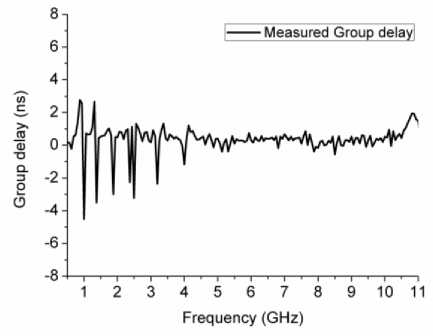
The group delay is shown in Fig. 9. Group delay is a very important requirement in UWB antennas since it represents the degree of distortion in the pulse signal. The group delay should be almost constant for good pulse transmission. As noticed in Fig. 9. The UWB frequency range maintains quite a stable ripple of about ≤1ns in almost the entire UWB band. The other narrow bands otherwise show highly varying group delays as expected. It is therefore satisfactory to say that, even with the added narrow-bands on the same UWB antenna, the integrity of the UWB antennas-performance isn’t distorted.
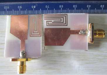
Fig.5. Photograph of the fabricated prototype
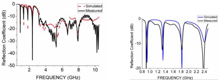
Fig.6. Simulated and measured results of the proposed multiband antenna showing the effectives of proposed technique. NB. Diagram on the right shows enlarged picture of the added bands for visibility
E Fi eld[V_per_ni

6.00006+004
2.3323е+00Ч
9.06616+003
3.52426+003
1.36996+003
5.32516+002
2.07006+002
0.04646+001
3.12786+001
1.21586+001
Colorkey
-
Fig.7. E-field distribution at different resonant points
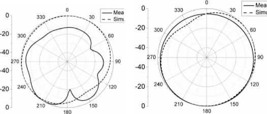
Fig.8. (a): E-( left ) and H-( right ) plane radiation pattern of the penta-band antenna at 0.95
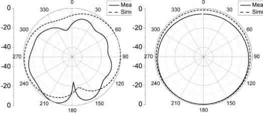
Fig.8. (b): E-( left ) and H-( right ) plane radiation pattern of the penta-band antenna at 1.3 GHz
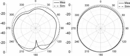
Fig.8. (c): E-( left ) and H-( right ) plane radiation pattern of the penta-band antenna at 1.8 GHz
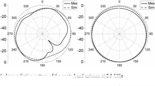
Fig.8. (d): E-( left ) and H-( right ) plane radiation pattern of the penta-band antenna at 2.5 GHz
-
Fig.8. (e): E-( left ) and H-( right ) plane radiation pattern of the penta-band antenna at 6 GHz
-
Fig.9. Measured group delay of proposed antenna
-
6. Conclusions
A planar monopole UWB antenna with integrated narrow communication frequency bands is presented. The UWB frequency band in the proposed penta-band antenna was satisfied by using about half of the conventional radiator size, with affecting its performance, thereby creating extra space to implement the narrow band technique for achieving a penta-band antenna with the same size. The narrow bands were achieved by using quarter wavelength folded CLLRs “hanged” from a non-resonant horizontal strip attached to the top of the miniaturized rectangular radiator. The measured results show that the proposed antenna has been designed for 3.1 – 10.6 GHz UWB band, 2.4 GHz WLAN band, 1.8 GHz GSM band, 1.3 GHz GPS band and 0.95 GHz RFID band, resulting in a miniaturized multiband antenna. The proposed antenna provides a new technique in achieving a multiband UWB antenna and is suitable for portable handheld and/or indoor wireless communication systems. Further research will be focused on introducing circular polarization into the GPS band.
References Miniaturized planar monopole UWB antenna with integrated RFID/GPS/GSM/WLAN bands using capactively loaded loop resonator (CLLRs)
- Chaimool S. and K. L. Chung, “CPW-fed mirrored-L monopole antenna with distinct triple bands for WiFi and WiMAX applications,” Electron. Lett., vol. 45, no. 18, pp. 928-929, Aug. 2008.
- Lin T. H. and D. C. Park, “Compact dual-band antenna with double L-slits for WLAN operation,” IEEE Antennas Wireless Propag. Lett., vol. 4, pp. 249-252, 2005.
- Kuo Y. L. and K. L. Wong, “Printed double-T monopole antenna for 2.4/5.2 GHz dual band WLAN operations,” IEEE Trans. Antennas Propag., vol. 51, no. 9, pp. 2187-2192, Sep. 2003.
- Mohammed S. A. N. and H. R. Hassani, "A novel tri-band E-shaped printed monopole antenna for MIMO application,” IEEE Antennas Wireless Propag. Lett., vol. 9, pp.576 -579, 2010.
- Zhang X.-Q., Y.-C. Jiao and W.-H. Wang,” Compact wide tri-band slot antenna for WLAN/WiMAX applications," Electron.Lett., vol. 48, no. 2, pp.64 -65 2012.
- Liu P., Y. Zou, B. Xie, X. Liu and B. Sun, “Compact CPW-fed tri-band printed antenna with meandering split-ring slot for WLAN/WiMAX applications," IEEE Antennas Wireless Propag. Lett., vol. 11, pp.1242 -1244, 2012.
- Yildirim B. S., B. A. Cetiner, G. Roquetra, and L. Jofre, “Integrated Bluetooth and UWB antenna,” IEEE Antennas Wireless Propag. Lett., vol. 8, pp. 149-152, 2009.
- Chu Q.-X. and L.-H. Ye, “Design of a compact dual-wideband antenna with assembled monopoles,” IEEE Trans. Antennas Propag., vol. 58, no. 12, pp. 4063-4066, Dec. 2010.
- Foudazi A., H. R. Hassani, and S. M. Ali Nezhad, “Small UWB planar monopole antenna with added GPS/GSM/WLAN bands," IEEE Trans. Antennas Propag., vol. 60, no. 6, pp. 2987-2992, 2012.
- Ryu K. S. and A. A. Kishk, "UWB antenna with single or dual band-notches for lower WLAN band and upper WLAN band," IEEE Trans. Antennas Propag., vol. 57, no. 12, pp. 3942 -3950, 2009.
- Mehranpour M., J. Nourinia, Ch. Ghobadi and M Ojaroudi, “Dual Band Notched Square Monopole Antenna for Ultrawideband Application,” IEEE Antennas Propag. Lett., vol. 11, pp. 172-175, 2012.
