Mixed QoS Controlled Wireless Streaming Media Transmission Strategy

Author: Fu Xianping, Men Yugang
Journal: International Journal of Information Technology and Computer Science(IJITCS) @ijitcs
Article in issue: 1 Vol. 3, 2011.
Free access
Streaming media applications is currently limited by high bandwidth requirements. It is a challenging problem to provide the required quality of service (QoS) for the efficient transmission of video data under the varying network conditions such as the time-varying packet loss and fluctuating bandwidth. On Internet the most important part for streaming media transmission application is QoS control mechanism which including two kinds of QoS control method, based on end to end and network. A wireless streaming media forward platform based on the mixed quality-of-service (QoS) control system is introduced in this paper. The theoretical knowledge related to the quality of service and mixed quality of service control of the feasibility and characteristics are analyzed, and introduced a comprehensive quality of service in theory. This system combines network control and end to end quality of service control. The network of the system is optimized to support quality of service, using the underlying network devices, network bandwidth optimization, network structure adapted to meet the both ends of the quality of service. At both ends, from the delay, jitter, etc. are adjusted, by the addition of the timestamp and other information on the dynamic adjustment of the speed of data transmission. Through improving the control of two ends QoS and media streaming forward server, the video streaming from ships on the sea is transferred to the Internet by microwave and then linked to common Internet and mobile phone users through carrier networks(wired and wireless), which realized the real time supervision.
Streaming media, quality-of-service, mobile media streaming, video Surveillance, congestion control
Short address: https://sciup.org/15011605
IDR: 15011605
Text of the scientific article Mixed QoS Controlled Wireless Streaming Media Transmission Strategy
Published Online February 2011 in MECS
Along with the quick development of the Internet, real time supervision, video on demand, distance education, video conference, videophone associated with media streaming technology is becoming more and more important on Internet. At the same time with the development of wireless technology, make it possible to extend media streaming technology under wireless even mobile wireless conditions. But the characteristic of the media streaming technology determines its difference from those conventional media forms. Congestion of the wireless and wired network, the high error code rate of the wireless channel and its time-varying, the heterogeneity of the network and terminal user, standby time and the portable of the terminal all make the transmission capacity of the media streaming restricted in wireless network. So it’s the key question of the wireless media streaming quality of service to research how to rationalize the net resources, control the congestion and faults during transmission effectively, provide satisfying service for users as far as possible, increase earnings of the operator.
The real time transmission of the multimedia databases is the crux of the media streaming technology. Great databases transmitted by the multimedia would take a long time in transmission process over which the Internet conditions are all dynamic and random, for what it is common to appear congestion and generate the decline of video quality the user receipted and even break off. Three questions need to be solved for the media streaming technology [1] on the Internet:
-
(1) how to make the streaming in transmission adapt to the real time changes;
-
(2) how to minimize the congestion;
-
(3) how to recover the transmission as soon as possible when congestion occurred.
Quality-of-service (QoS) controlled technology is an effective method to ensure the transmission quality. Its settlement is equaled to solve the three questions in media streaming transmission. QoS controlled system is not by increasing the bandwidth but based on the original internet to optimize the network, manipulate the cache to satisfy the requirement of all kinds business and realize the transmission of media screaming.
Internet QoS control in general can be divided into two categories: control based on end to end and control in basis of network. Established in the two transmission ends QoS control [2-5], an Internet cloud formed abstracting from the transmission medium. It guarantees the quality service according to monitoring and feedback from the client, flow control and congestion control of the server, which belongs to application layer QoS technology.
At present, to improve the control based on end to end is the direct means, but it is less effective. Although these technologies are helpful for the video application based on IP net, there is also clear fault: Only adapt the current status of the network passively but can not propose QoS [6] requirement to get QoS service initiatively. The fundamental is the present IP Network Architecture only provides best effort but not specific quality assurance for the specific business. Based on these works, the research on QoS guarantee mechanism is developed popularly and having gotten a lot of achievements which provides new opportunity for the commercialization of Internet video services. Because network QoS service can not provide absolute quality guarantee, end to end system is also needed to provide favorable guarantee mechanism. Therefore, Network QoS guarantee service and control system based on end to end system are complement.
In this paper we developed a forward platform on the basis of QoS controlled network. Through improving the control of two ends QoS and media streaming forward server, the video streaming on sea is accepted to the Internet by microwave and then linked to common Internet and mobile phone users through carrier networks( wired and wireless ), which realized the real time supervision.
-
II. STRUCTURAL ANALYSIS
-
A. QoS control analysis
QoS is a security mechanism of network to settle network delay and network congestion. Under normal circumstances, if network only used in the application system without time limit, there is no need of QoS, e.g. web application or E-mail set up. But it’s necessary when network overload or congestion which can guarantee the business can not be delayed or lost, at the same time to ensure efficient operation of the network.
Media streaming transmission needs to meet the correlative targets of the QoS [7-8]. It mainly in the following categories:
-
(1) Throughput: In order to ensure the play of the media streaming, minimum bandwidth requirements are needed for the transmission and the lower network supplies a link bigger than the minimum bandwidth to the upper network.
-
(2) Delay and shake: the real time characteristic of the media streaming transmission requires the data package arrived earlier before play, otherwise, even it have arrived there’s no use. Though the buffer mechanism has softened the requirement for delay and shake, buffer size is restricted by the acceptor system and overlarge of the buffer leads longer delay time. Obviously, it’s no proper for the application of video conference and videophone. Therefore, a certain mode is needed to ensure the delay and shake requirement for media streaming transmission system.
-
(3) Error rate and packet loss rate: Error rate and packet loss can lead to frame loss or decoded which cause decline in play quality. Only control the error rate and
packet loss rate in a certain range can ensure the playback quality of media streaming.
-
(4) Smoothness: Namely, send rate can not have violent shake. When the media streaming play, the stability of the play quality needs maintained and stream rate should be matched with sending rate. So guarantee the smoothness of sending rate is necessary to ensure stable playback quality.
-
B. Streaming media transmission strategy Based on QoS
Network transmission based on QoS should build upon Network Transport Protocol [9]. There are a lot of protocols about streaming real-time transmission, according to their functions can be divided into the following categories:
-
1. Network layer protocol: It provides basic web service support. The main protocol of network layer is IP protocol and unreliable service is its primary feature. That is to say it only sent the grouping from source node to objective mode fast and reliable service like QoS can not be guaranteed.
-
2. Transport layer protocol: It provides network transmission from point-to-point. Transport layer protocol includes User Datagram Protocol (UDP), Transmission Control Protocol (TCP), Real-time Transport Protocol/Real-time Transport Control Protocol (RTP/RTCP). UDP and TCP are transfer protocols in transport layer which at the bottom of the structure. While RTP and RTCP are upper transfer protocol, realized on top of the UDP and TCP. Each data in TCP and UDP transfers in internet through each router port layer in system and middle layer [10].
-
3. Session Control Protocol (Application Layer protocol): Its main function is session description. In an established session define information and process to control the stream media data. Real-time streaming protocol (RTSP) and Session Description Protocol (SDP) are typical Session Control Protocol.
|
application layer |
SDP |
|
|
RTSP |
||
|
transport layer |
RTP |
|
|
TCP |
UDP |
|
|
network layer |
IP |
|
Figure 1. Protocol layers
The workflow of the RTP and RTCP transport video stream is described in Fig.2 :At the video server streaming media is loaded to RTP Data payload section in packets format and configured parameters such as timestamp packet header by RTP database, synchronizing information, Order number, namely change data packets into a stream simultaneously accepting RTCP packets periodically, utilize the above information to change self parameter set-up dynamically. When client accept database packet, it analysis the RTP packet header firstly and check the validity of the version and load type information. And update the RTP information in buffer such as byte count, video frames, packets and order
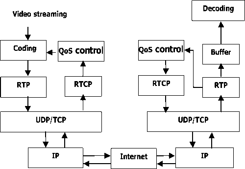
Figure 2.Forwarding system workflow based on RTP/TCP
number; Secondly, synchronization source, collate order of the RTP database package, reconstruct of the video frame according to RTP timestamp and order number; Finally, decode according to the load type mark and load the database in buffer for output of the decoder. While client send back RTCP [11] package containing QoS feedback control information according to the information periodicity in RTP to server to check the consistency of transmitter and receiver.
Flow control and congestion control are important method to realize QoS. For TCP data stream, congestion control based on windowed strategy was usually used. Once congestion is tested, congestion window can be reduced by half instantaneously. A rapid deceleration of the TCP data stream will make part of the data postponed; therefore, it is not suitable for the data transmission of streaming media. For streaming media transmission, rate control strategy is usually used. According to the bandwidth pre-estimated, it can be realized by adjusting the sending rate or receiving rate. Rate control can be realized both in receiver and sender.
Analysis multimedia data streams rule on network delay and congestion, TCP response function can be regarded as calculation formula for adjusting sending rate:
T =
s
R
) P (1 + 32 p 2)
T represents the theoretical maximum of TCP sending rate under steady state, s is the package size, R represents corresponding rate of round-trip time, P represents the packet loss ratio in Steady state, t RTO is the retransmission time of TCP.
1.22*MTU RTT * p
λrepresents the maximum throughput of sender, MTU is the maximum transmission unit, RTT represents corresponding rate of round-trip time, P represents the packet loss ratio in Steady state.
III. EXPERIMENT.
-
A. Platform Construct
We developed a media streaming platform (Fig.3) based on the establishment of the QoS network and the analysis of streaming video transmission strategy combined with our practical application. It is a forwarding platform on the basis of streaming media forwarding server. It response to requests from client including common Internet and mobile phone users and then link with the head-end DVR in ship on the sea or seaport through cable network or microwave wireless system, after that forward the accepted video data to client asked for a request[12].
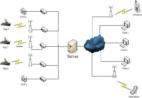
Figure 3.Streaming Media Platform structure
The purpose of installing streaming server is to ease end station tension of the network bandwidth and forward requested video from end station through streaming server softly, making the end station video services only occupy one channel. Multi- level set of the streaming media management software module can meet the QoS requirement through improving the efficiency of responding to access and planning the set-up of the streaming server rationally, consequently, in price of shorter time to get higher bandwidth utilization.
Live server receives video streaming first and then forward again. Streaming server served as a platform between live streaming server and client which decline the pressure of the live streaming server and answer all requirements of the client collected. Live streaming server lied in the center of the Web cast service provide live services for client continually so it is powerful and reliable, Streaming media server cluster technology can meet this requirement effectively. The combination of the live streaming server and load balancing device can realize the distribution of the fodder and dispose the edge server, which declining the possibility of network congestion, enhancing the error rate and smoothness, intensifying the possibility of QoS.
The reception quality of client was not only controlled by the number of users connected to servers but also the network congestion. In streaming media transmission process, network congestion can lead to packet loss and time lag, which influenced the play quality of client. The main cause for the congestion was mass data crowded in network. Therefore, as the sending end, streaming relay server should take more control policy than client. To effectively avoid congestion, the flow control should be taken in the sender. In case of congestion, a passive strategy would be taken by the streaming media server.
When network congestion happened, the scheduling strategy of router decide which data packet should be transmitted. Data stream are allocated through a router that arrange the transmission order of data packet. Streaming media server can be taken as network equipment with router function, whereas its output was DVR. But there are some thing in common for the scheduling strategy of router and streaming media server.
Different with those traditional wireless video forward platforms, video capture point of this platform have both wired and wireless video collection points. And the Wireless video collection points are dynamic and dissociate. These wireless video collection points are existed in moving ships equipped with DVR. The video information is transmitted to base station (Fig.4) through wireless microwave technology and then establish communication with forwarding server. The wireless
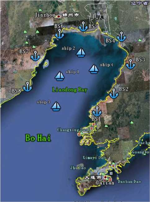
Figure 4.Wireless microwave transmission base station distribution. In Liaodong Bay with eight base stations scattered around. When the sea vessels equipped with omnidirectional antenna, a base station close to a base station to establish communication with the nearest base station, the video streaming to the Internet transmission of the head end is affected by weather clearly which leads the decline of QoS guidelines such as Bit Error Rate and delay. Therefore, it brings trouble for QoS control.
In view of the above-mentioned facts, it is important to exam the time delay, packet loss and jitter for client player. The examination of client should be conjugate to sender and then feedback to sending server. Information of timestamp and data packet numbers are added in the streaming media packets of sender, which are helpful for the calculation of time delay so as to judge if there is a packet loss. The examination of packet loss can assure if there is congestion in network, it is the most important factor for network examination.
In virtue of information loaded in data packet, the interval time was calculated between two packet losses. Data packets number transmitted in this interval time was set as an important index. Larger the index number, less possibility of the network congestion would be.
Receiver feedback the data received in a certain interval time to servers. Sender analysis the feedback results, and then resent the loss data or adjust sending rate. If there was not feedback information from client in a certain time, the network may be congested and sender’s congestion control is needed.
-
B. information structure of Communication
As the streaming media is forwarded by the telecommunications network, the video control Platform should have to comply with the telecommunications network monitoring specifications. The version of current control technology telecommunications is Version2.0. The communication between the client and server is described in the form of SIP structure. The header of SIP agreement entirely adopts the SIP header structure, and XML structure is used in the message body part.
SIP is based on the model of request / response transaction. It accomplished locating user, session establishment and management by using information. SIP messages are divided into two categories: SIP requests and SIP responses. The basic format of SIP messages are as follows:
Generic - message = start-line
*message-header CRLF
[Message-body]
Start - line= Request - Line/Status – Line
General SIP message is consist of the start line, message header and message body. SIP requests and SIP responses are different in the starting line. The size of the SIP message will not exceed 40KBytes.
SIP request for the beginning of the act:
Request-Line=Method SP Request-URI SP SIPVersion CRLF
SIP response to the start of behavior:
Status-Line = SIP-Version SP Status-Code SP ReasonPhrase CRLF
-
C. System components
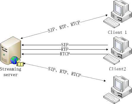
First transmission between server and client is used to establish communication; the communication link between them is shown in Fig 5. In this network system, there are three data link. The first is UDP-based SIP message channels; its main function is from the client to the server to send control commands and video requests.
The format for the SIP message headers and XML message body, after the server receives the message to parse the message and respond to the request, then respond through the SIP according to the response message back to the client. The second is the RTP data link, which is mainly responsible for the road link between the server and the client-side video data transmission, transmission of video information effectively. The third is RTCP data link, which is mainly responsible for the QoS transmit RTP data link information, the server according to the information can be sent automatically to dynamically adjust the stream to meet the real-time network status.
After client to parse the request message of SIP, the next job is to respond to requests, to communicate with
Clients
Figure 5.Link Map between Streaming server and Client
the DVR. Client and the communication link between the DVR as shown in Fig 6.
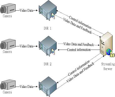
DVR 3
Figure 6.Link Map between Streaming server and DVR
From the chart, there are three data links in the communication between server and DVR. One is Control information to the DVR server,such as user login, PTZ control, OSD settings, etc. The other links are a report to the server of state feedback from DVR, such as network congestion, the video disappeared, video block, dynamic monitoring, etc.
Based on the underlying platform, forward platform on Application layer is completed. By the combination of B/S and C/S framework and using QoS forwarding mechanisms realize the media streaming forward. Schematic framework is shown in Fig. 7
Firstly, users select surveillance location to view the captured video through web page quickly, and then
Web Browser

HTTP/TCP
Web Server

Locate
Source
Streaming player
RTP/RTCP
RTSP
Streaming server
Figure 7.The diagram of streaming forwarding. The upper 、left corner is the Web browser, through its Quick Find web Server to the latest data, and open the bottom right corner of the streaming player, a request to respond to connection streaming Server access to the latest configuration through the server-side. When a user requests, the player installed on the client run automatically, video data are transferred to the player, and connected to the server, at last the client view the server's forwarding video streaming, which realize the real time surveillance based on QoS.
IV RESULTS
After the system built, in order to make the stability of the system, a test procedure is done to get plenty of data, and the data are analyzed by the relevant information. Tests are mainly carried out through the following aspects, including network bandwidth, system consumption, video quality, the number of requests, connecting channels and so on. Test data based on the feedback of information, the structure of the system of local adjustment, the relevant algorithm is optimized. The following specific tests will be the process of data analysis in detail.
During the test, take a variety of different state at different number of requests and different connection points, respectively, and the bandwidth utilization, memory consumption, CPU usage and other parameters of these states were recorded, as shown in Table 1. From table 1, with increase of the number of requesting and connection points, the share of the bandwidth and memory utilization also increased. But the CPU utilization rate of increase is not great, so we can see that CPU running in good condition. However, the use of the bandwidth increase is obvious, when the number of requests increased to a certain number that will appear the phenomenon of network congestion. Thus we can see the network speed is a key factor in system stability constraints.
Streaming media forward server in the whole system plays the most critical role and it is the center of the
Table1. Parameter Table
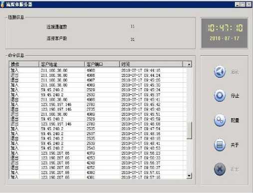
Figure 8.The figure show the forwarding state when the server linking 31 users at the same time the corresponding video request and the connection point 11 video captures
We have successfully developed and implemented a platform which can forward the video stream real- time in basis of forwarding network under QoS control combined with two ends QoS control technology. After solving problems such as forwarding delay, packet loss, errors and so on, we can get clear real time images like those shown in Fig.9
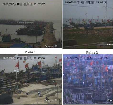
Point 3
Point 4
Figure 9.Four randomly selected location of video surveillance. The former two is wireless transmitted while the following two are wired.
V DISCUSSION.
This paper proposes a wireless streaming media forwarding system structure based on Mixed QoS Controls, combined with end to end network quality of service optimization and control technology, streaming media data streams transmitted. The paper stated streaming forward theories based on the combination of the physical environment, builds a real environment downstream media forwarding platform, which forwards the server to establish a critical role in server-side combination of network and client feedback, do the rate adjustment, and in the event of network congestion, the congestion control strategy used to restore the network. Client data packets accord to the sender timestamp and serial number and other information on the current network status feedback. Tests show that the proposed wireless streaming media forwarding system structure based on Mixed QoS Controls, capable of carrying multiple multi-user requests and forwards streaming media environment forward task.
A CKNOWLEDGMENT
Supported in part by “the Fundamental Research Funds for the Central Universities”
DVR accurately linked.
References Mixed QoS Controlled Wireless Streaming Media Transmission Strategy
- G. Eason, B. Noble, and I. N. Sneddon, “On certain integrals of Lipschitz-Hankel type involving products of Bessel functions,” Phil. Trans. Roy. Soc. London, vol. A247, , April 1955 pp. 529–551.
- H.Schulzfinne, S.Casner, R.Frederick.RTP: A transport Protocol for Real-time Applications.IETFRFC l989 , January l989.
- BYERS J W, HOM G LUBY M, ET a1.FLID-DL: congestion control for layered multicast [J].Selected Areas in Communication IEEE Journal, 2002, 28:pp.1558-1570.
- Ma Liangping, Arce Gonzalo R.TCP retransmission timeout algorithm using weighted medians [J].IEEE Signal Processing Letters 2004 11(6), pp.569-572.
- J. Clerk Maxwell, a Treatise on Electricity and Magnetism, 3rd ed., vol. 2. Oxford: Clarendon, 1892, pp.68–73.
- I. S. Jacobs and C. P. Bean, “Fine particles, thin films and exchange anisotropy,” in Magnetism, vol. III, G. T. Rado and H. Suhl, Eds. New York: Academic, 1963, pp. 271–350.
- W.Stevens.TCP Slow Start, Congestion Avoidance, Fast Retransmit, and Fast Recovery Algorithms, IETF RFC 2001..
- R. Branden and others. Resource Reservation Protocol (RSVP) :Version 1 Functional Specification. IETF RFC 2205.
- A.Mankin and others. Souse Reservation Protocol(RSVP):rsion1 Applicability Statement, me Guidelines on Deployment, TF RFC2208..
- HoeJ.ImProving the start-up Behavior of a congestion Control Scheme for TCE.In:Proc, of ACM SIGCOMM’96.tandford,A,August 1 996.Pp.270-280
- R. Nicole, “Title of paper with only first word capitalized”, J. Name Stand. Abbrev. In press.
- Y. Yorozu, M. Hirano, K. Oka, and Y. Tagawa, “Electron spectroscopy studies on magneto-optical media and plastic substrate interface,” IEEE Transl. J. Magn. Japan, vol. 2, , August 1987, pp. 740–741.
- M. Young, the Technical Writer's Handbook. Mill Valley, CA: University Science, 1989.
