Mobile device to collect heat and power parameters of the refrigerator

Author: Shurinova D. A., Kovalenko А. N., Myrygin A. V., Suvorov A. G.
Journal: Siberian Aerospace Journal @vestnik-sibsau-en
Section: Informatics, computer technology and management
Article in issue: 1 vol.22, 2021.
Free access
The article deals with the system used to reduce the amount of time to carry out the refrigeration tests; it was developed to cut the acceptance testing time of each refrigerator up to 6-9 minutes. The main parts of the system , considering each piece of equipment separately and its role in the system as a whole, the way all devices connected to a single unit, communication protocol, cloud storage method to access data from any mobile device are described in the article. The main purpose of the system is to measure the temperature at certain points of the refrigerator capacitor when it is connected to the power grid. The analysis of the thermal energy properties of the refrigerator, combined with the analysis of the cooling speed of the refrigeration chambers (as well as the heating of the capacitor) makes it possible to understand whether each refrigerator corresponds to certain characteristics established by GOST. The article also presents the characteristics of the devices being used (temperature meter-regulator TRM 138, the ME110-224-1M electrical network measurement module).
Heat and energy characteristics of the refrigerator, acceptance tests, refrigerator capacitor.
Short address: https://sciup.org/148321788
IDR: 148321788 | UDC: 62-529 | DOI: 10.31772/2712-8970-2021-22-1-70-80
Text of the scientific article Mobile device to collect heat and power parameters of the refrigerator
Introduction. One of the topical problems of today's refrigeration production is a problem of quite timeconsuming acceptance tests .As a solution of this problem, the authors of the article made a decision to develop a new testing technique that requires less time. In order to create a new technique of controlling the heat and energy parameters of refrigerators in conveyor mode, it is necessary to collect information of temperature distribution at different points of the capacitor in accordance with the electrical power consumed by the compressor. This requires the development of a multi-channel system to allow these measurements to be taken and their values accumulated.
The new method should provide the monitoring of the refrigeration cooling system parameters in 6-9 minutes keeping in mind:
-
- changes in ambient temperature
-
- the initial temperature of the internal refrigerator cupboard;
-
- the initial temperature of the compressor.
To develop the new method, you need:
-
- extended collection of temperature values at 8-12 points of capacitor and internal refrigerator cupboard with thermocouples and thermo resistance;
-
- information about current values and compressor power consumption
-
- the value of voltage in the power grid.
The article describes the development of a portable mobile system which helps you to measure and accumulate the values of these parameters at any interval of time (up to 24 hours). The resulting settings will be stored in a cloud server. This service allows you to store a large amount of information that will be available from any mobile device.
Temperature measurement . Fig. 1 shows the of the thermosensors' attachment locations installed to control the distribution of temperature through the capacitor tubes and the compressor of the refrigerator wall.
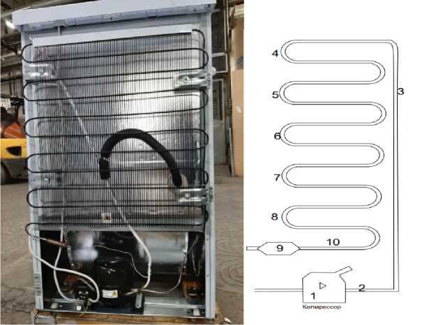
Рис. 1. Расположение мест крепления термодатчиков на конденсаторе холодильника
-
Fig. 1. Location of the thermo sensors on the refrigerator capacitor
At points 2–9 the condenser temperature variations are from 16 to 60 C. range .Temperature range at point 1 (on the compressor itself): from 16 to 120C. As the capacitor tube has a mall diameter and the side wall of the compressor has uneven surface, the thermocouples of HK grades with a minimum diameter of the worker sleeping approximately equal to 0.5 mm. will be used as thermo sensors. Special clamps will be used to attach the thermocouples to the capacitor (Fig. 2), when the sensor attachment to the compressor will be provided with a sticky tape.

Рис. 2. Зажимы для крепления термопар к конденсатору холодильника
-
Fig. 2. Clamps to attach thermocouples to the refrigerator capacitor
Fig. 3 shows the thermo sensors position[2] in the refrigeration chamber.
In the freezer chamber, the sensors are similar.
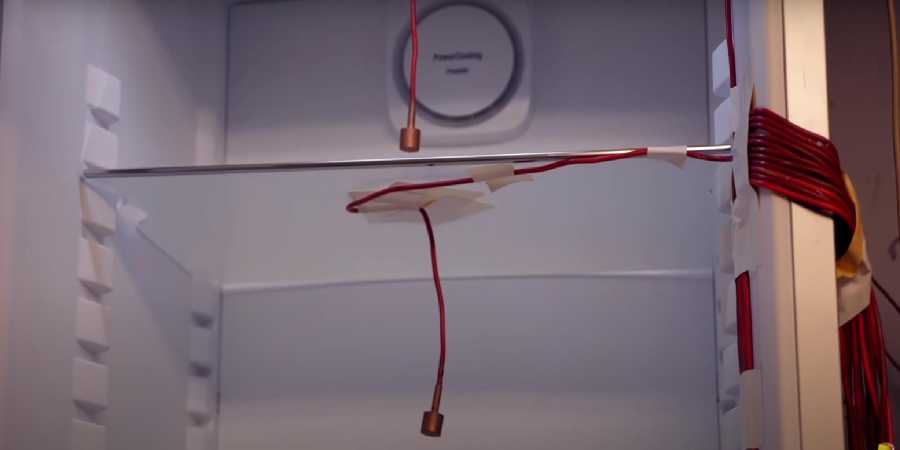
Рис. 3. Показано положение термодатчиков в холодильной камере
-
Fig. 3. The position of the temperature sensors in the refrigerating chamber is shown
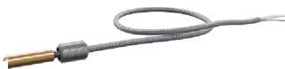
As sensors we use thermo-resistance of 50M grade (Figure 4, a). To ensure that the refrigeration door is closed tightly, the sensors are connected by a flat cable [4].
а
б
Рис. 4. Термосопротивление градуировки 50М [5] ( а ); ТРМ138 восьмиканальный регулятор с RS-485 [6] ( б )
Fig. 4. Thermal resistance of calibration 50M [5] ( а ); TPM138 eight-channel controller with RS-485 [6] ( b )
TRM 138 is used as a temperature measurement device (Figure 4, b). The 138 TRM 138 is able to communicate through the RS 485 interface, to make corrections for each of the measurement channels individually, and has a convenient indication. The thermosensors connection is done according to the scheme
(Fig. 5).
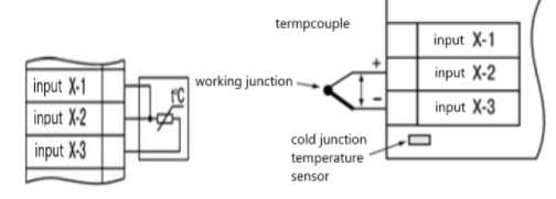
termpcouple input X-1
working junction cold junction temperature sensor
а
б
Рис. 5. Подключение термосопротивления ко входам прибора ТРМ 138 [8] ( а ); подключение термопары ко входам прибора ТРМ 138 ( б )
Fig. 5. Thermal resistance connection to the TPM 138 device inputs [8] ( а ); thermocouple connection to TPM 138 device inputs ( b )
To prevent the interfering the device's readings two stages of digital measurement filtering are performed for each channel:
The first step is to exclude peaks and dips that stand out from the main signal. To do this, the system automatically monitors the new incoming signal values, if the new value differs from the previous value by a larger than the pre-set filter strip (defined for each of the sensors by a separate parameter), then the input signal will be filtered by the system. Too small filter strip setting results in slowing down the sensor's response to a dramatically changing input.
The second stage is smoothing out measurement results ; the damping parameter can be set up; the more the coefficient, the slower the reaction of the device to the input change (Fig. 6, 7).
Рис. 6. Зависимость уровня от постоянной времени фильтра
Fig. 6. Level dependence on filter time constant
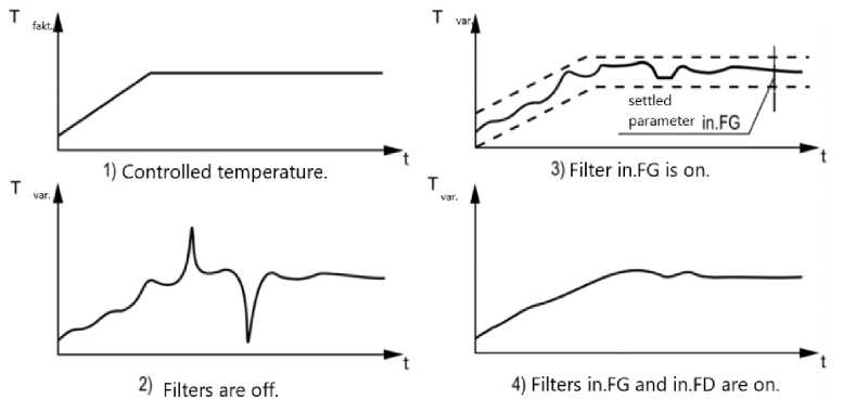
Рис. 7. Временные диаграммы работы цифровых фильтров
-
Fig. 7. Time diagrams of digital filters operation
To eliminate the initial error of the input conversion, and the errors caused by the impact of the adjacent wires, the measured value is probably to be corrected. The device is able to carry out 2 types of correction, implementing a shift or tilt of the characteristic to a given value.
-
1) Characteristic shift (Fig. 8). It consists of summing up the measured value with a certain user-defined value entered through the parameters. For each measuring channel, the offset value is set individually [8].
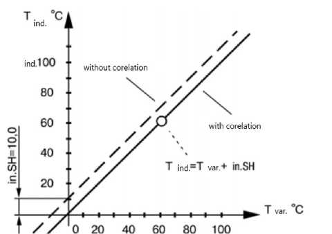
Рис. 8. Пример применения коррекции типа «сдвиг характеристики»
-
Fig. 8. An example of a "characteristic shift" correction
-
2) Characteristic tilt changing (Fig. 9). The correction takes place due to the multiplication of the adjusted value by the factor entered in the parameters by the user. This ratio is different for each measurement channel.
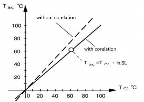
Рис. 9. Пример применения коррекции типа «наклон характеристики»
-
Fig. 9. An example of a "characteristic slope" correction
The second type of correction is recommended at the measured values close to the maximum, where the measurement error becomes greater. Both types of correction are possible to apply to the measurement channel at the same time.
Power consumption measurement . When measuring the power consumed by the compressor we can establish a time-connected relationship between temperature distribution and the electrical energy spent on it.
Based on the parameters of electricity consumption, we will be able to measure:
-
- compressor power voltage (220B ± 10%);
-
- current power (0–2A);
-
- cos ɸ ;
-
- active power (0–200 w).
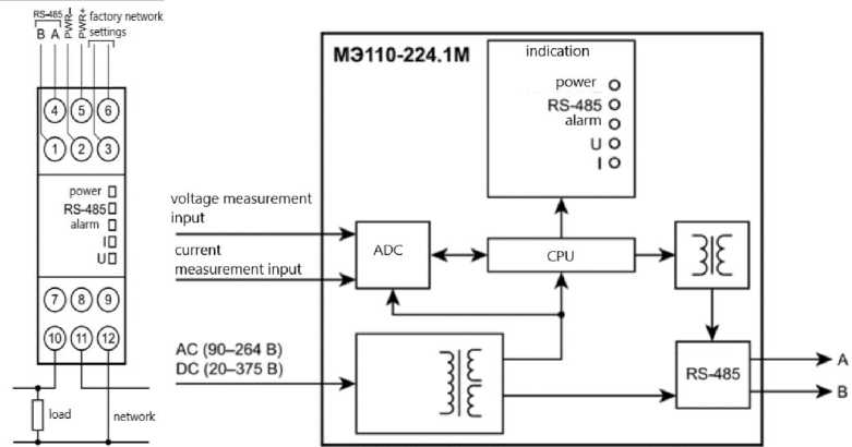
ME110-224-1M meter is used to measure these parameters. The refrigerator unit power meter connection scheme is shown on Fig. 10 [10]. The refrigerator power supply is used as a load in our case.
а
б
Рис. 10. Подключение модуля измерения параметров электрической цепи питания холодильника ( а ); структурная схема прибора ( б )
Fig. 10. Connecting the electrical circuit measurement module (a); structural scheme of the device (b)
The parameters measurement is as follows (Figure 11)[11]
1) The current voltage is measured by converting the input signal by a voltage divider and signaling to the lower frequencies filter. Further signal processing is carried out by the ADC and the microcontroller, which calculates the current voltage value under the following formula:
Vrms = Kv (1 ^ T )* J V 2( t ) dt
Where V is the value of phase voltage; T is a period; Kv is a voltage transformation factor.
2) The current is measured by passing the input through the current shunt and then to the lower frequencies filter. Further signal processing is performed by the ADC and the microcontroller, which calculates the current value of the current according to the following formula:
T
Irms = Ki (1 ^ T ) * f I 2 ( t ) dt
3) Full, active and reactive power is calculated by the device according to the following formulas. Full:
Active:
S = Vrms * Irms
S = Vrms * Irms * cos ф
Reactive:
S = Vrms * Irms *sin ф
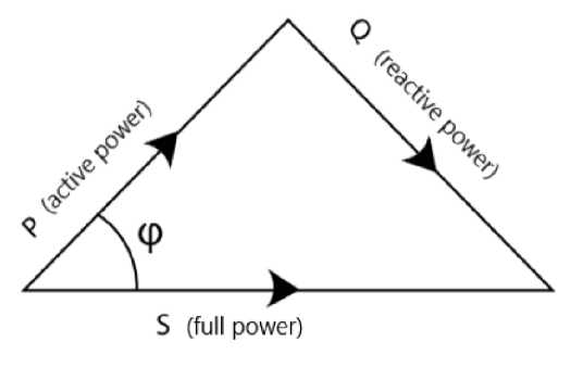
Рис. 11. Диаграмма соотношения мощностей
Fig. 11. Power ratio diagram
Collection and accumulation of measured values . To collect and store temperature and electrical data on the OwenCloud cloud server, we use PM210 Network Gateway to access the OwenCloud RS-485 service <– > GPRS. The communication of the devices via RS 485 [12] is shown in Fig. 12.
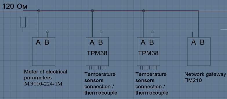
Рис. 12. Связь приборов по RS 485 [12]
Fig. 12. Communication of devices via RS 485 [12]
Aries Cloud service is used to view the data received from the device remotely, as well as to preserve temperature information in time-bound. To add the device to the service, we introduce the parameters of the device (Fig. 13) on the site of Aries Cloud.
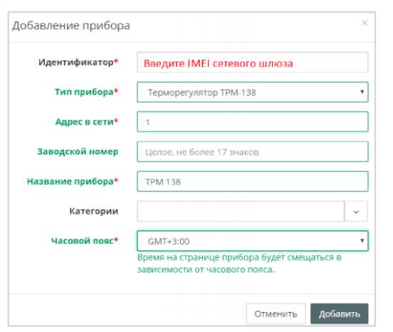
Рис. 13. Добавление прибора в облачный сервис ОВЕН для просмотра значений температуры дистанционно
Fig. 13. Adding the device service to view temperature values remotely to the ARIES cloud
Then we set the parameters of communication of the device with the modem (the type of device, time zone, etc.), the protocol of communication we choose is ModBus (Fig. 14) [14].
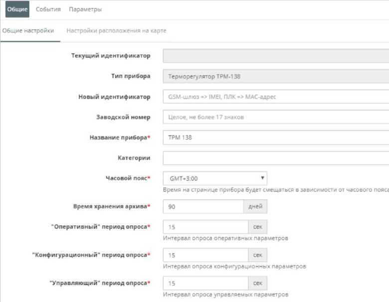
Рис. 14. Задаваемые параметры общения модема с прибором
The temperature values you receive can be viewed in the form of a graph (Fig. 15) or as a table (Fig. 16), which allows you to display the information visually. The viewer will immediately pay attention to the big swings; the deviation from the norm will be also obvious when viewing the graph. The time graphic dependence of the parameter immediately helps you to detect up-to-date information about the particular refrigerator.
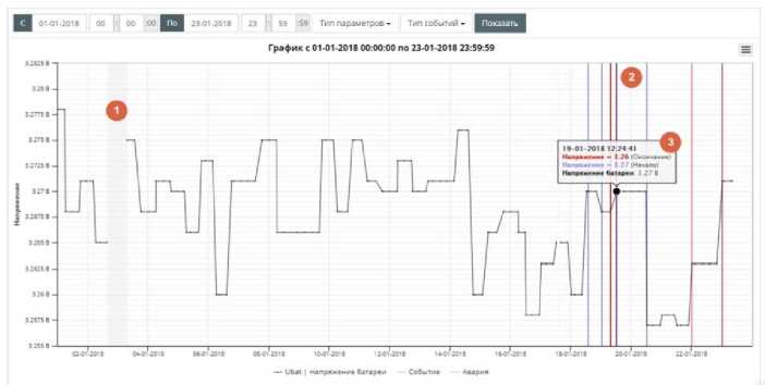
Рис. 15. Графический вывод параметров
Fig. 15. Graphic parameters output
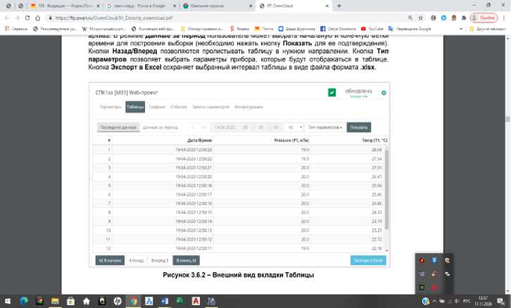
Рис. 16. Вывод параметров в виде таблицы
Fig. 16. Parameters output in the form of a table
Data access to the cloud service is available from any device connected to the Internet.
Conclusion. The system developed by the authors of the article allows to apply the new method of conducting refrigerators acceptance tests described at the beginning of the article with much less time costs. This system is the first step to the introduction of a new method at the enterprise. [15].
References Mobile device to collect heat and power parameters of the refrigerator
- GOST 16317–87. Priboryholodilnueelektricheskiebitovye. Obshietehnicheskieysloviya [State Standard 16317–87: Household electrical refrigeration appliances. General technical conditions (with amendments Nо. 1, 2, 3)]. Moscow, Standartinform Publ., 1987. 22 p.
- Voloshin I. F., Kasperovich A. S., Shashkov A. G. Polyprovodnikovyetermosoprotivlenya [Semiconductor Thermal Resistance]. Minsk, Publishing house Acad. Sciences BSSR, 1959, 197 p.
- Gradyirovka 50 m [Graduation 50 m]. Available at: http://elektrouzel.ru/ instrumentation/calibration/71-graduirovka-50m.html (accessed: 10.10.2020) (In Russ.).
- Kabel plosky [Flat cable]. Available at: https://www.chipdip.ru/catalog/flat-cable (accessed 10.11.2020). (In Russ.)
- Termosoprotivlenya s kabelnym vivodom [Thermoresistance with cable outlet]. Available at: https://insat.ru/products/?category=2609&gclid=CjwKCAiA7939BRBMEiwAhX5Jz2YnJJeq0e3VmD DwRZcc8IugT2LlYXDYfZiQq4QCKQf4wvhZwu7SRoCzMQQAvD_BwE (accessed: 11.10.2020). (In Russ.)
- Vosmikanalny regylator s RS485 [Eight-channel thermostat with RS-485]. Available at:https://owen.ru/product/trm138/price (accessed: 10.11.2020). (In Russ.)
- Thomas Kugelstadt. Gidpo structure RS485. Otchetpoprimeneniy SLLA272C [The RS-485 Design Guide. Application Report SLLA272C]. Febuary 2008–Revised October 2016. 10 р.
- Shemy podkluchenya TRM138 [Connection diagram for TRM138]. Available at: https://owen.ru/product/trm138/connection (accessed: 13.10.2020). (In Russ.)
- Moduli izmerenya parametrov electrycheskoi tsepi [Modules for measuring electrical network parameters]. Available at: https://owen.ru/product/moduli_izmereniya_parametrov_elektricheskoj_seti (accessed: 13.10.2020). (In Russ.)
- Manual ME110-224-1M. 50 р. Available at: https://owen.ru/uploads/re_me110-224. 1m_2092.pdf (accessed: 13.10.2020). (In Russ.)
- OVEN. Modul elektroizmeritelnyy ME110-224.1M. Rukovodstvo po ekspluatatsii 02.2020 versiya 1.13. [OVEN. Module for measuring the parameters of electrical network ME110-224.1M. Manual. Version 1.13]. Available at: https://owen.ru/product/moduli_izmereniya_parametrov_elektricheskoj_seti (accessed: 13.10.2020). (In Russ.)
- Jan Axelson. Serial Port Complete: Programming and Circuits for Rs-232 and Rs-485 Links and Networks. 1998, 380 р.
- Owen Cloud [OwenCloud]. Available at: https://owen.ru/owencloud (accessed 10.13.2020). (In Russ.)
- Rinaldi J. Modbus: The Everyman's Guide to Modbus.Createspace Independent Publishing Platform. 2015, 92 р.
- Owen Cloud. Oblachny servis. Rykovodstvo polzovatelya [OwenCloud.Cloud service. Userguide]. 09.25.2020. Version 1.07.
