Mobile Robot Navigation using Fuzzy Limit-Cycles in Cluttered Environment

Author: Fatma Boufera, Fatima Debbat, Lounis Adouane, Mohamed Faycal Khelfi
Journal: International Journal of Intelligent Systems and Applications(IJISA) @ijisa
Article in issue: 7 vol.6, 2014.
Free access
This paper proposes a hybrid approach based on limit-cycles method and fuzzy logic controller for the problem of obstacle avoidance of mobile robots in unknown environment. The purpose of hybridization consists on the improvement of basic limit-cycle method in order to obtain safe and flexible navigation. The proposed algorithm has been successfully tested in different configurations on simulation.
Mobile Robot, Obstacle Avoidance, Limit-Cycles Method, Fuzzy Logic
Short address: https://sciup.org/15010577
IDR: 15010577
Text of the scientific article Mobile Robot Navigation using Fuzzy Limit-Cycles in Cluttered Environment
In unstructured environments, robot controller must be able to operate under conditions of imprecision, uncertainty and respond efficiently to events [1], [2], [3], [4], [5]. The obstacle avoidance is an essential component to achieve successful navigation. Several trajectory tracking and path following algorithms have been proposed to steer the mobile robot along a path to a desired goal.
Many researches turned their attention to the obstacle avoidance problem. They developed interesting real-time methods and algorithms for mobile robots navigation in unknown environments. Some famous classical obstacle avoidance methods that must be cited are:
-
- The potential field method introduced by [6] and improved in [7]. This method assumes that the robot is driven by virtual forces that attract it towards the goal, or reject it away from the towards the goal.
-
- Vector field histogram method introduced by [8] and improved by [9]. It corresponds to local occupancy grid, constructed from the sensors of the robot.
-
- The deformable virtual zone method, introduced by [10]. It can be applied to any form of obstacle, hence its efficiency.
-
- Limit-cycles method introduced by [11] and improved by [12] (cf. Section III).
Other interesting obstacle avoidance algorithms inspired from artificial intelligence tools and relatively suitable for real-time and embedded applications can be cited [13]:
-
- Neural Network: This approach is applied in [14] to determine the optimal neural networks structure for real-time obstacle avoidance task. The author in [15] proposed a neural network that uses Qlearning reinforcement technique for solving the problem of obstacle avoidance.
-
- Multi-Agent System: The author in [16] proposed a new local collision avoidance algorithm between multiple robots for real-time navigation is presented. This algorithm is based on multi-agent system and quadratic optimization method for a collision free navigation and robot path planning.
-
- Hybrid genetic Algorithm: The authors in [17] used a hybrid genetic algorithm with neural network and local search method for solving the problem of finding the optimal collision free path in complex environments for mobile robot.
-
- Particle Swarm: Optimization (DPSO) to solve the problem of obstacle avoidance for multi-robot system.
This paper deals the obstacle avoidance problem for a non-holonomic mobile robot in unstructured environment while using a new hybrid approach based on limit-cycles method and fuzzy logic for different shapes of obstacles. The limit cycles method despite to its effectiveness in obstacle avoidance has some imperfections presented by oscillations in the robot trajectory during its passage around the obstacle especially when it is very close [12].
To solve this problem and while insuring that the robot path will be more flexible, this paper develops an inference system based on fuzzy logic add to the obstacle avoidance module.
Besides this introduction, the structure of the paper is as follows: Section II gives the specification of the robot posture. Section III presents the control architecture based on the limit-cycles method and inference fuzzy system. Section IV is devoted to the description and analysis of the simulation results. Conclusions and future work are given in Section V.
( ̇̇̇)=(
соѕ sin
- соѕ - sin
- sinθ+ соѕ )( ) (1)
With:
-
• х,у,θ : Configuration state of the unicycle at the point " " of abscissa and ordinate ( , ) according
to the mobile reference frame( , ).
-
• : Linear velocity of the robot at the point "p".
-
• w: Angular velocity of the robot at the point "p".
-
II. Robot Posture
Let x(t), y(t) and z(t) represent the robot’s position at time t in some global coordinate system (Ω), and let the robot’s orientation (heading direction) be represented by 9(t). The quadruplet (x, y, z, 9) describes the robot’s kinematic configuration. In our case, the used robot (Fig.1) has two independently drive wheels at a distance d, with fixed maximum wheel velocity Vmax and maximum wheel acceleration a . max.
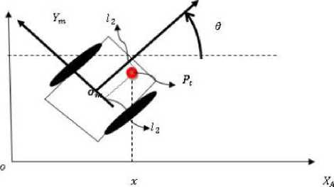
Fig. 1. Robot configuration in a Cartesian reference frame
-
III. Proposed Hybrid Obstacle Avoidance
-
3.1 Attraction To The Target Controller
This section describes the behavior control architecture for navigation, obstacle avoidance and attraction to the target based on limit-cycles method [12] and fuzzy logic in unstructured environment.
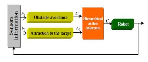
Fig. 2. Control architecture for mobile robot navigation [12]
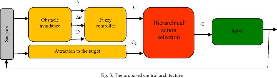
The proposed architecture is an extension of the control architecture presented in [12] (cf.Fig.2). A fuzzy inference module is added downstream of the obstacle avoidance module (cf.Fig.3). The fuzzy rules used by this module allow the robot to correct its trajectory by the reduction of the oscillations produced by the limit-cycle method during its passage around the obstacle especially when it is very close.
The robot moves in the search space from its initial position to the target. The used method to achieve this behavior is an on-line approach. The robot must reach a given target radius R c and center coordinates (x c ,y c ) expressed in the coordinate of the robot [19].
Position errors are defined as
= - = соѕ(2)
= - = sin(3)
d is the distance of robot to the target and can then be expressed as
=√ +(4)
is the orientation error, such that 9 ∈ ]- и , и ] is
̃=tan ( - )- 6 (5)
Derivative of ̃ is then
̃̇=(; ̇ ;) ⧸ (1+( 5 )2)-" (6)
Margin corresponds to a safety tolerance which includes: perception incertitude, control reliability and accuracy, etc.
Rd = + Rr + ∈
After computation using the kinematic model (cf. equation (1) and equation (2) we obtain
= WT -W
Where
sin( ̃)
V--—
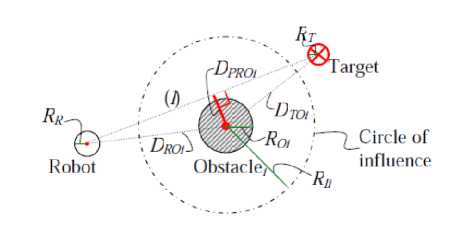
Fig. 5. The used perceptions for mobile robot navigation [12]
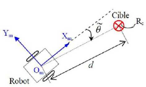
Fig. 4.Variables used for Attraction to the target Controller
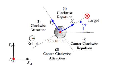
Fig. 6. The four specific areas surrounding the obstacle to avoid [12]
-
3.2 Obstacle Avoidance Controller
-
3.2.1 Limit-Cycles Method
A new real-time obstacle avoidance using hybrid approach for mobile robot has been developed and implemented. This approach permits to the mobile robot to avoid obstacles and going toward the target simultaneously. It is composed by two sub-modules: obstacle avoidance module based on limit-cycles method (cf. Section III.3.1) and Fuzzy logic controller (cf. Section III.3.2).
The proposed control architecture integrates obstacle avoidance method which uses limit-cycle. Summarily, the obstacle avoidance algorithm follows these steps [12]:
The robot trajectory needs to be safe, smooth and fast. One supposes in the setup that obstacles and the robot are surrounded by bounding cylindrical boxes with respectively R0 and Rг . The target to reach is also characterized by a circle of R т radius. Several perceptions are also necessary for the robot navigation (cf. Figure.5):
-
• d Distance between the robot and the obstacle"i".
-
• RQI Radius of the obstacle "i" to avoid,
-
• For each detected obstacle we define a circle of influence with a radius of
Rri = + Roi + Margin (9)
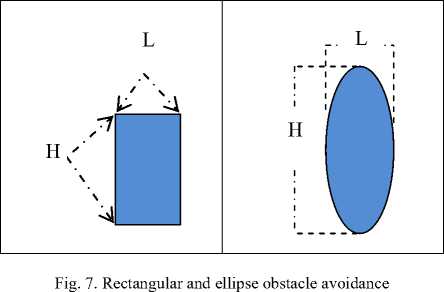
If the obstacle has a rectangular shape, square or ellipse, the radius of the obstacle will be:
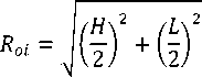
With: L is the width of the obstacle and H the height of the obstacle (cf. Figure 7).
The differential equations representing the desired trajectory of the robot are given by the following system
X ̇ = + xr ( Ri - Xy - ^) (12)
̇r= + xr ( Ri - Xy - Ут ) ( 13)
With a = ∓ 1 according to the souhaitable direction of avoidance (clockwise or counterclockwise irection).( xT , Уг )are the relative robot coordinates with respect to the obstacle[12].
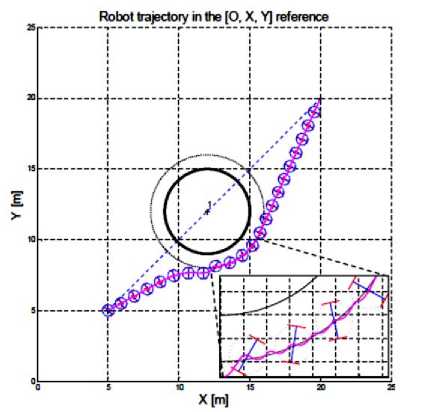
Fig. 8.Robot trajectory oscillations [12]
only a small portion of the in input space. The controller gives a path in some internal reference frame and it generates motor commands in order to follow it as closely as possible.
The following table 1 presents several research works on the application of fuzzy logic as obstacle avoidance method.
Table 1. Fuzzy Logic Research for Obstacle Avoidance
|
Authors |
Approach |
Environment |
Objective |
|
[25] |
Fuzzy control |
Unknown |
Navigation and obstacle avoidance |
|
[26] |
Fuzzy traversability index |
Cluttered |
Terrain based navigation for multi-robot |
|
[27] |
Fuzzy control |
Ocean |
Control and collision avoidance for vehicles |
|
[28] |
Robust fuzzy logic controller |
Cluttered |
Path tracking For Non-holonomic vehicle |
|
[29] |
Fuzzy control |
Dynamic |
Obstacle avoidance and target seeking |
|
[30] |
Fuzzy control |
Dynamic |
Obstacle avoidance and target seeking |
Figure 8 shows an example of the limit cycles method application. The robot avoids the obstacle in counterclockwise according to method principle. We remarks oscillations in the trajectory when the robot skirts the obstacle. The robot to oscillates between the position where D RO i ≤ R Ii (activation of “obstacle avoidance” controller) and D ROi ≥ R Ii (activation of “attraction to the target” controller).
-
3.2.2 Fuzzy Controller
The proposed obstacle avoidance strategy combines the limit-cycles method with fuzzy logic. The main objective of the proposed method is to reduce the robot orientation change in obstacle avoidance behavior, without affecting the efficiency and the safety of the avoidance.
The use of Fuzzy Logic founds different application in the area of control system design, where human expert knowledge, rather than precise mathematical modeling, of a process or plant is used to model/implement the required controller. Uncertainty and ambiguity are evident in many engineering problems [20]. Fuzzy Logic Control (FLC) therefore provides a formal method of translating subjective and imprecise human knowledge into control strategies, thus facilitating better system performance through the exploitation and application of that knowledge [21].
In general, there are two approaches to the application of fuzzy logic in mobile robot navigation, namely, behavior-based approach [22] and classical fuzzy rule based approach [23], [24]. The overall control problem is decomposed into small behaviors, each one focusing on
In the current work, we use a single-input single-output Mamdani-type a Fuzzy Logic Controller (FLC) [31] as shown in Fig.9.
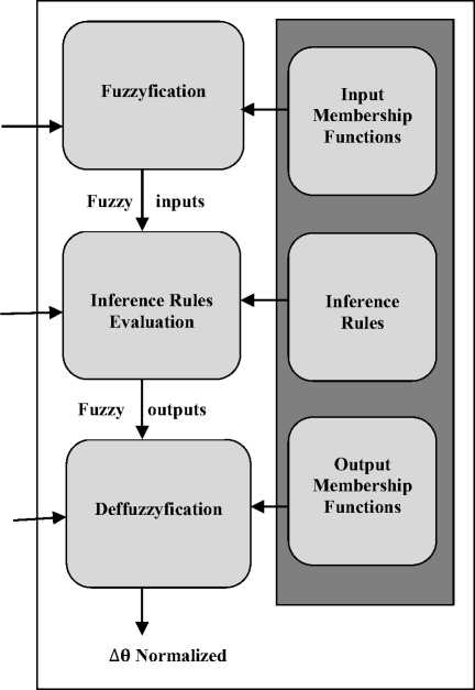
Fig. 9. Internal structure of Fuzzy Controller used in Fig.3
The fuzzy controller inputs are:
-
- D: is the separation distance between the robot and the obstacle without collision.
-
- Δ 6 : Is the change in robot direction (left or right).
-
- N: is the number of change Δ 6 per unit of time Δ т .
The fuzzy controller output is Δθ normalized. The aim of introducing FLC is to decide on the amount of tune up normalized Δ 6 according to N, Δ 6 and D that the robot has to apply to its current direction to converge to its target position. The fuzzification and defuzzifiation membership functions are taken as linear triangular and trapezoidal membership functions for their higher computational efficiency. The intelligent mobile robot reactive behavior is formulated by means of fuzzy rules. Inputs of the fuzzy controller are: The membership functions of the robot orientation change which is represented by five fuzzy intervals: LLG (Left LarGe), LL (Left Little), Z (Zero), RL (Right Little) and RLG (Right LarGe).
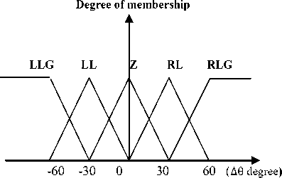
Fig. 10. Representation of fuzzy subsets of Δ 0
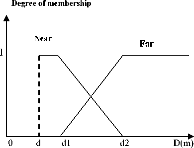
Fig. 12. Representation of D distance fuzzy sets
The membership functions of output variable: normalized change orientation angle of the robot standard which is represented by five fuzzy intervals: LLG (Left LarGe), LL (LeftLittle),Z (Zero), RL (Right Little), RLG (Right LarGe), RVL (Right Very Little) and LVL(Left Very Little).
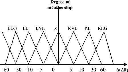
Fig. 13. Representation of fuzzy subsets of normalized Δθ
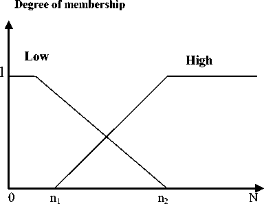
Fig. 11. Representation of fuzzy subsets of N
The obstacle distances D is simply expressed using two linguistic labels membership functions near and far .
Table 2: Set of input and output inference rules.
|
IF |
D |
Δ 0 |
N |
THEN |
Δ0 normalized | |
|
F |
LLG |
L |
LL |
||
|
F |
LL |
L |
Z |
||
|
F |
Z |
L |
Z |
||
|
F |
RL |
L |
Z |
||
|
F |
RLG |
L |
RL |
||
|
F |
LLG |
H |
LVL |
||
|
F |
LL |
H |
Z |
||
|
F |
Z |
H |
Z |
||
|
F |
RL |
H |
Z |
||
|
F |
RLG |
H |
RVL |
||
|
N |
LLG |
H |
LL |
||
|
N |
LL |
H |
LVL |
||
|
N |
Z |
H |
Z |
||
|
N |
RL |
H |
RL |
||
|
N |
RLG |
H |
RVL |
||
|
N |
LLG |
L |
LL |
||
|
N |
LL |
L |
LVL |
||
|
N |
Z |
L |
Z |
||
|
N |
RL |
L |
RL |
||
|
N |
RLG |
L |
RVL |
The following steps concern the development of rules to define the expected behavior of the robot according to its intrinsic parameters. For each combination of values of the input variables, an action on the output variable is associated with it. We obtain 20 fuzzy rules. The following table summarizes the set of rules:
-
IV. Simulation Results
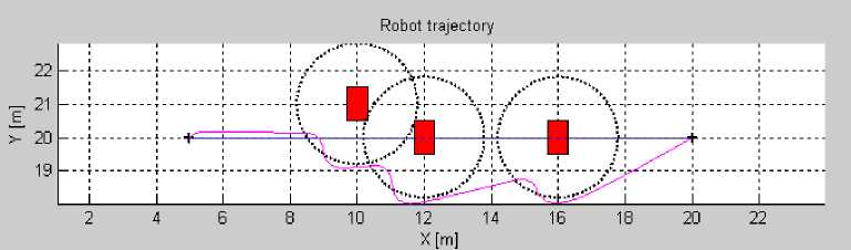
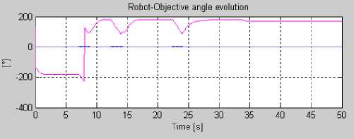
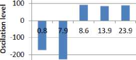
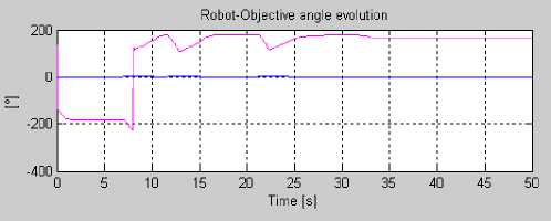
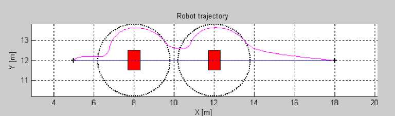
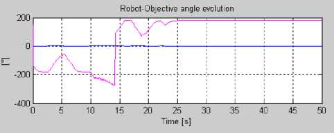
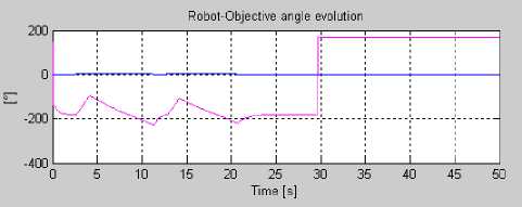
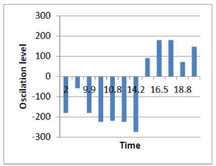
To confirm the relevance of the proposed control architecture, it is proposed to simulate a mobile robot navigation to reach a target in presence of obstacles for different robot configurations and different environments. Each Simulation is made twice. In the first case, we used only the limit-cycles method for obstacle avoidance (cf.Fig.15(ai) and Fig.16(ai)). In the second case, the proposed control architecture is implemented on the robot (limit-cycles method combined with fuzzy logic) (cf.Fig.15(bi) and Fig.16(bi)).The robot trajectory oscillations are presented by the orientation change peaks of the robot when it avoids the obstacle.
(a 1 )

(a 2 )
(b 1 )
-300 J---
Time
(b 2 )
(c 1 )
300 J----------—--
(c 2 )
Fig. 15. Scenario of navigation1: (ai) without fuzzy controller,(bi)with Fuzzy controller
(a 1 )
(a 2 )
(b 1 )
(c 2 )
Fig. 16. Scenario of navigation2: (ai) without fuzzy controller,(bi) with Fuzzy controller.
(b 2 )
(c 1 )
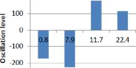
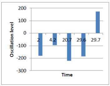
The bars in the figure have been obtained by a sampling process of the robot trajectory function. We only take the function samples representing a direction change which exceeds a certain threshold empirically set equal to 10°.
In the two cases, the robot reaches its target while avoiding obstacles. However, by comparing robotobjective angle evolution during obstacle avoidance (cf. Figures 15 and 16), it is noticed that the number of angle change is reduced.
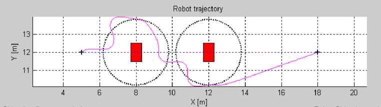
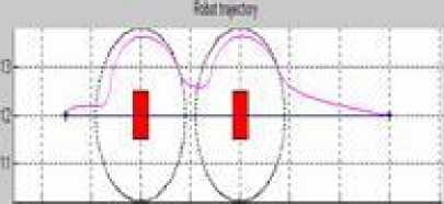
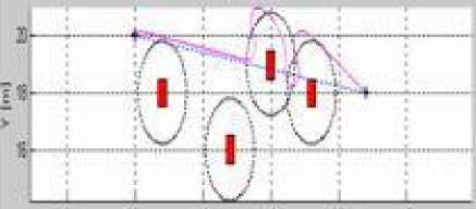
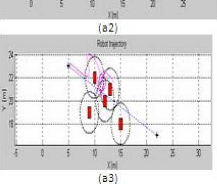
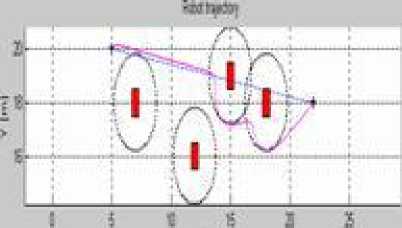
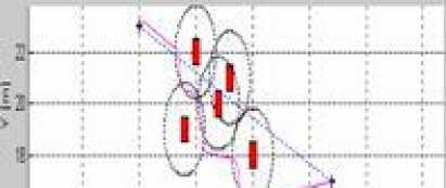
In order to test more the efficiency of the hybrid approach (limit-cycles with fuzzy logic), we compare in Figure 17 the robot trajectories obtained with and without fuzzy logic for different simulation cases of obstacle avoidance. This figure shows that the robot trajectory for the three simulations cases are smoother, the navigation is more flexible and the robot is able to reach the target with hybrid approach essentially when the environment is complex (obstacles very close to each other) (as seen in the third case (b i ).
: i t 4 11 n 1 E 1

fH
(al)
w
(Ы)
^hftij]
(b2)
41 Ц£?-
._________; vz——_________L i i i a s i
(b3)
Fig.17. Robot trajectory comparison, (ai) without Fuzzy controller,(bi) with Fuzzy controller.
-
V. Conclusion
In this work, simulation results show the efficiency of the proposed control architecture which uses Fuzzy controller to implement a hybrid approach based on the method of limit-cycles and a fuzzy controller. The purpose of this combination is to make the avoidance more flexible by reducing the number of orientation shift during the avoidance. The perspective of this work is to optimize this approach by making it more intelligent and also to make experiments on real robots.
References Mobile Robot Navigation using Fuzzy Limit-Cycles in Cluttered Environment
- Brooks, R.A. 1986. A Robust Layered Control System for a Mobile Robot. IEEE Journal of Robotics and Automation, RA-2, pp.14-23.
- HachourOuarda, “Intelligent Autonomous Path Planning Systems,” International Journal of Systems Applications, Engineering and Development, Issue 3, Vol. 5, pp. 377-386, 2011.
- Adouane, L and LeFort-Piat N. 2004. Hybrid Behavioral Control Architecture for theCooperation of Minimalist Mobile Robots, In Proceedings of the International Conferenceon Robotics and Automation ICRA04. pp. 3735-3740, New Orleans-USA.
- Meyer, J.A, and D. Filliat. 2003. Map-based navigation in mobile robots, a review of map-learning and path-planning strategies. Journal of Cognitive Systems Research, 4(4):283317.
- Luzeaux, D, and A. Dalgalarrondo. 2003. Hybrid architecture for autonomous robot based on representation, perception and intelligent control. Studies in Fuzziness and Softcomputing. Recent Advances in Intelligent Paradigms and Applications. ISBN 3-7908- 1538.
- Khatib M. and H. Jaouni, R. Chatila& J.P. Laumond. Dynamic Path Modi_cation for Car-Like Nonholonomic Mobile Robots. IEEE International Conference on Robotics and Automation, pages 2920_2925. Albuquerque, USA, 1997.
- Khatib, O. 1986. Real time obstacle avoidance for manipulators and mobile robots. Internationaljournal roboticsresearch, 5(1), 90-80.
- Koren, Y, and J. Borensrein. 1991. Potential Field Methods and their inherent limitations for mobile robot navigation. IEEE conference on robotics and automation, PP.1398-1404.
- Ulrich, B. 1998. Reliable obstacle avoidance for fast mobile robots. in IEEE intconf on robotics and automation. Leuven, Belgium.
- Zapata, R, and P. Lepinay. 1994. Reactive behaviors of fast mobile robots. Journal ofrobotics system, vol.11, pp. 13-20.
- Kim, D, and J. Kim. 2003. A real-time limit-cycle navigation method for fast mobilerobots and its application to robot soccer, Robotics and Autonomous Systems, vol. 42, pp.17-30.
- Adouane, L. 2009. Orbital obstacle avoidance algorithm for reliable and on-line mobile robot navigation. In Proceedings of the In 9th Conference on Autonomous Robot Systems and Competitions.
- Adouane, L, and A. Benzerrouk, and P. Martinet. 2011, Mobile Robot Navigation in cluttered Environment using Reactive Elliptic Trajectories, In Proceedings of the 18th IFAC World Congress, Milano-Italy,August 2011.
- Hoang, T and T. Nguyen. 2007. Obstacle Avoidance for Power Wheelchair Using Bayesian Neural Network, Proceedings of the 29th Annual International, Conference of the IEEE EMBS, CitéInternationale, Lyon, France, August 23-26, 2007.
- Duguleana, M, and F. Barbuceanua, and A.Teirelbarb, and G.Mogana. 2012. Obstacleavoidance of redundant manipulators usingneuralnetworks based reinforcement learning, Robotics and Computer-Integrated Manufacturing, Volume 28, Issue 2, April 2012, Pages 132146.
- Guy, S, and J.Chhugani and C.Kim and N.Satish and M.Lin and D. Manocha andP.Dubey. 2009. ClearPath: Highly Parallel Collision Avoidance for Multi-Agent Simulation.Eurographics/ ACM SIGGRAPH Symposium on Computer Animation (2009), E.Grinspun and J. Hodgins (Editors).
- Hosseinzadeh, A and H.Izadkhah. 2010.Evolutionary Approach for Mobile Robot Path Planning in Complex environment, IJCSI International Journal of Computer Science Issues,Vol. 7, Issue 4, No 8, July 2010.
- Couceiro, M.S, and R.P. Rocha and N.M.F. Ferreira. 2011. A novel multi-robot exploration approach based on Particle Swarm Optimization algorithms. Safety, Security, and Rescue Robotics (SSRR), 2011 IEEE International Symposium on.
- Benzerrouk, A,Adouane, L. and Martinet, P. 2010, Lyapunov Global Stability for a Reactive Mobile Robot Navigation in Presence of Obstacles Braitenberg, V. 1984. Vehicles. MIT Press, Cambridge MA.
- Saffotti, A. and E. Ruspini H, and K. Konolige. 1999. Using fuzzy logic for mobile robotcontrol. In: Zimmermann HJ, editor. Practical applications of fuzzy technologies, KluwerAcademic; p.185-206.
- Lee, and Wang. 1994. Collision Avoidance by Fuzzy Logic Control for Automated guidedVehicle Navigation, Journal of Robotics Systems, Vol. 11 No.8, pp 743-760.
- Aguirre, E, and A. Gonzalez. 2000. Fuzzy behaviors for mobile robot navigation: Design, coordination and fusion. International Journal of Approximate Reasoning, Vol. 25, No. 3, 255-289.
- Xu, W.L. 2000. A virtual target approach for resolving the limit cycle problem in navigationof a fuzzy behavior-based mobile robot. Ibid, Vol. 30,315-324.
- Zavlangas, P.G, and S.G. Tzafestas, and K. Althoefer. 2000. Fuzzy obstacle avoidanceand navigation for omnidirectional mobile robots. In Proceedings of the ESIT 2000, Aachen,German.
- Saffoti, A, 1997, the uses of fuzzy logic in autonomous robot navigation, Soft computing, pp 180-297, 1997
- Seraji H, 2000, Fuzzy Traversability Index: A new concept for terrain-based navigation, Journal of Robotic Systems, 17(2), pp. 75-91, 2000.
- Kanakakis, V. Valavanis, K. P. & Tsourveloudis, N. C. (2004). Fuzzy-Logic Based Navigation of Underwater Vehicles. Journal of Intelligent and Robotic Systems, Vol. 40,45-88.
- Moustris, G., & Tzafestas, S. 2005. A Robust Fuzzy Logic Path Tracker for Non-holonomic Mobile Robots. International Journal on Artificial Intelligence Tools,14 (6), (2005), pp.935-966
- Menon M., Muhletaler F., Campos M., Peabody J.O. (2008) Assessment of early continence after reconstruction of the periprostatic tissues in patients undergoing computer assisted (robotic) prostatectomy: results of a 2 group parallel randomized controlled trial. J Urol 180: 1018–1023
- Boubertakh H, Tadjine M, et al. 2010. Tuning fuzzy PD and PI controllers using reinforcement learning. ISA Trans 49 (4): 543-51.
- Mamdani, E.H. 1977. Application of Fuzzy Logic to Approximate Reasoning Using LinguisticSunthesis. IEEE Transactions on Computers, Vol. C-26, No. 12.
