Modeling and verification of working process parameters in gas generators for pressurizing fuel tanks of liquid propellant rocket propulsion systems

Author: Sheludko M.L., Nazarov V.P., Zenyuk K.O., Nazarova L.P.
Journal: Siberian Aerospace Journal @vestnik-sibsau-en
Section: Aviation and spacecraft engineering
Article in issue: 3 vol.23, 2022.
Free access
The main requirements for LRE gas generators are high stability of operation, ease of workflow management, as well as high efficiency of the generator gas. A particularly difficult task is to ensure the sustainability of the workflow. In addition to the probability of transverse vibrations in the in-chamber volume, due to the presence of additional volumes of various configurations and lengths attached to the reaction chamber, acoustic vibrations of complex longitudinal modes may occur. Most of the existing methods of testing a gas generator are criterion-empirical in nature and are based on the processing of experimental results, which does not always provide the required accuracy of calculating dynamic and thermal characteristics. The need for experimental and theoretical refinement of the calculation methods of thermodynamic processes of gas generators is an urgent task that will significantly reduce the material and time costs for preliminary design, testing and fine-tuning of modern models of engines and power plants of aircraft. Therefore, the calculation and analysis of the LRE gas generator is an important stage in the design and development of modern engine designs. Using the finite element method of the SOLID WORKS software package, a model of a two-zone gas generator for supercharging fuel tanks of the LRE was built. A study was conducted on modeling the workflow in a gas generator, visualization of thermodynamic processes in the product was built, numerical characteristics were obtained. The method of autonomous bench (firing) tests of fuel tank supercharger gas generators, the method of verification of numerical methods are considered.
Two-zone gas generator, finite element method, fire tests, verification of calculations
Short address: https://sciup.org/148329647
IDR: 148329647 | UDC: 662.76.032 | DOI: 10.31772/2712-8970-2022-23-3-520-530
Text of the scientific article Modeling and verification of working process parameters in gas generators for pressurizing fuel tanks of liquid propellant rocket propulsion systems
Stable and uninterrupted supply of liquid fuel components to the fuel lines of liquid-propellant rocket engines (LREs) is provided by a special system for supercharging the fuel tanks of aircrafts (in particular, ballistic missiles and space launch vehicles). The tank supercharging pressure is usually determined from the condition of cavitation-free operation of turbo-pump units (TPU) pumps, strength and stability of the tank shells. The pressure of fuel components at the inlet to the engine pumps Р вх is the sum of the pressure of the liquid column Р ст and the absolute pressure in the tank over the free surface of the liquid Р б . Taking into account pressure loss Δ Р вх in pipelines and fittings, located on lines from tanks to pumps, we get the following expression:
Р вх = Р б + Р ст – Δ Р вх . (1)
During the rocket flight, Р ст will change in accordance with the law of motion of the rocket along a given trajectory, while the value of Р вх must be kept constant.
To displace liquid components from the tanks, a hot displacer gas is supplied to the tank gas pads, which in many liquid rocket engines (LREs) is created in special two-component liquid gas generators (LGGs), which are called supercharger gas generators. It is considered most rational to use fuel components in supercharger gas generators that are the same as the fuel in the main (thrust) chamber of the LRE.
However, these fuels, when combusted at close to stoichiometric ratios, develop high temperatures that are inadmissible for feeding into the fuel tanks. Therefore, in supercharger gas generators, the working process should be organized in such a way that one of the components would ballast the fuel mixture with its excess, thereby lowering the combustion temperature.
The gas temperature acceptable for supercharging tanks is achieved by an excess of oxidizer ( α > 1) or an excess of fuel ( α < 1). Therefore, the gas obtained at α > 1 (oxidizing gas) is fed to supercharging the oxidizer tank, the gas obtained at α < 1 (reducing gas) is fed to the fuel tank [1].
The results of thermodynamic calculations at small and large values of the ratio of components α often do not agree with the experimental data. This is explained by the fact that the chemical equilibrium at relatively low temperatures does not have time to be established and there is a large heterogeneity in the composition and temperature of the combustion products in the volume of the gas generator chamber.
For two-component gas generators of fuel tank superchargers, it is advisable to use self-igniting fuels. However, even in this case, the organization of reliable ignition and stable combustion at large excesses of one of the fuel components is very difficult. Therefore, in addition to the scheme of direct mixing of fuel components with the proper α in the head area, there are other schemes, aiming at a more reliable and stable operation of the chamber [2].
One of the possible schemes is the two-stage fuel supply to the chamber, shown in Fig. 1. Here, combustible and oxidizer are fed to zone I of the head in a ratio that reliably ensures ignition and stable combustion, i.e. close to stoichiometric. Through an additional belt an excess of one of the components (depending on the type of gas generator) necessary for the corresponding temperature drop is fed into zone II .
In this process, a complex of interconnected thermogasodynamic processes occurs: atomization, evaporation, mixing, heat and mass transfer in the two-phase flow, participation in chemical reactions of an additionally injected component.
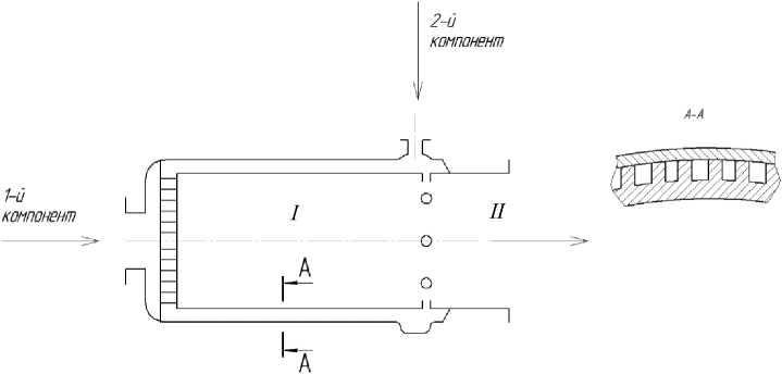
Рис. 1. Схема двухступенчатой подачи топлива в газогенератор
Fig. 1. Diagram of two-stage fuel supply to the gas generator
It should be noted that the thermodynamic parameters of the gas generated by this method at the chamber outlet will be different from those for the gas obtained at the same total value of α in the one-stage scheme. Experimental data on the complex process of evaporation and partial combustion of the excess component, as well as on the degree of equilibrium of the final gas mixture composition, are needed to calculate the scheme with two-stage fuel supply. Theoretical prediction of gas composition and temperature with complex hydrocarbon fuels is difficult.
The disadvantage of the method considered, in addition to the complexity of the design, is the difficulty of obtaining a uniform temperature field at the outlet of the generator chamber. Local peaks of temperature and gas pressure are also possible.
Thus, the goal of this work is to simulate the flow of the working body in a gas generator, obtaining the distribution of temperature gradients, and proposing a methodology for autonomous bench tests of gas generators of LREs for data verification.
Methodology
SOLIDWORKS software with the addition of Flow Simulation package was used for modeling the working process, which provides the construction of the working body flow model in the cavity of the gas generator model with regard to the thermophysical characteristics. The object of the study is a two-zone gas generator for supercharging fuel tanks of LRE. A 3D model of the gas generator was created (Fig. 2) using algorithms of three-dimensional solid modeling [3].
The setting of initial parameters was chosen on the basis of determining the pressure in the gas generator, also taking into account the material and properties of the working body.
The pressure in the gas generator is determined by the following formula:
pгг = mт ⋅ ϕгг ⋅ βгг / Fкр.т , (2)
T∗ -T where m is the mass flow rate of the fuel components; ϕ=12 0 is the coefficient characteriz- т гг T1- T0
ing losses in the nozzle; β гг is the flow complex; F кр.т is the area of the critical cross section in the gas generator.
During the calculations, for their accuracy, each of the parameters included in this formula will be taken into account [4].
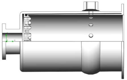
Рис. 2. Геометрическая модель газогенератора
Fig. 2. Geometric model of the gas generator
12Cr18Ni10Ti steel was used as the material of the inner wall. To estimate the thermal parameters of the solid body, the average working pressure in the combustion chamber was chosen to be 11MPa and the temperature to be 548 K.
In the Flow Simulation project the following parameters were selected. The type of the problem was determined by the internal medium. Selection of the option “thermal conductivity in solids” is a prerequisite for solving the problem with thermal conductivity. The next step is selection of the type of fluid medium and determination of the characteristic of the flow, in our case the flow is mixed. In the fluid-body system, the boundaries of the body define the surface limiting the fluid distribution area, i.e. the boundaries of the model body are the boundary conditions for the fluid-body system. The thermal condition on the outer wall is set by default to a heat transfer coefficient of 25W/m2 ⋅ K and an ambient temperature of 20.05 ºC.
The boundary conditions are the incoming flow velocity and the static pressure at the outlet of the calculation domain. The boundary condition at the inlet holes is set to flow velocity of 0.2 m/s. The next step in solving this problem is to add a heat source. To do this, we set the volumetric heat source -heat power of 2000 W to the heating element. The input data of the research project is shown in Fig. 3.
ф Проект(1)
В © Входные данные i i......Q Расчетная область i i......^ Подобласти течения i i......Материалы
; Ь-И раничные условия
I I И Скорость на входе 1
I I И Скорость на входе 2
-
1......И Статическое давление 1
| Й'^ Цели i......ГЦ Ср Статическое давление ......ГЦ Ср Температура (текучая
:......ГЦ Ср Температура стенки 1
Й-Щ Сетка
Й 'Эа Результаты (Не загружены)
Рис. 3. Входные данные проекта
-
Fig. 3. Project input data
Thus, as a result of the calculation the values of temperature of the working and solid body will be determined. All basic steps to solve the “internal” problem are done.
The methodology presented in this work gives a complete assessment of the thermodynamic parameters during the working process in the gas generator.
As a result of the calculation, not only numerical values of the gas temperature are obtained, but also the temperature distribution gradients on the inner wall of the gas generator combustion chamber are calculated on their basis (Fig. 4).
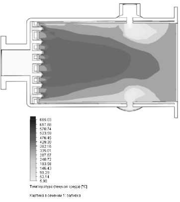
Рис. 4. Градиенты распределения температур
-
Fig. 4. Temperature distribution gradient
Depending on the project objectives, the software allows to determine the temperature at any point of the model.
The distribution gradient clearly shows the nature of the heating of the working body relative to the walls, which are cooled by the second component supply.
Indicators of the gas generation process
Any numerical simulation must be confirmed or disproved in the experiment. This paper proposes a methodology for data verification using autonomous bench tests of the gas generator of a LRE and further comparison of the values obtained during the tests with the values obtained by numerical simulation.
The purpose of the gas generation process is to prepare such a quantity of working body (gas) of certain parameters, with which it is possible to perform the required total work L for the task [5]. In this case the following amount of fuel components will be used:
L
Mкт =^^ , ηт Lуд where L is the theoretical specific work that 1 kg of fuel can produce; ηт is the coefficient of utilization of fuel in the gas generator.
The required second total consumption of fuel components for the gas generation process, assuming a constant flow rate over time, is mкт
ML кт
τ τηт L уд ,
where τ is the operating time of the gas generator as part of the aircraft. The relative consumption of fuel used in the gas generation process is
F = m- L.
8 - - , m τm ηтLуд where m is the second flow rate of fuel fed to the main chambers of the LRE.
The relative ε flow rate is a characteristic of the efficiency of the gas generation system.
The work required to displace the fuel from the tank of volume Vб at pressure pб , is l^- P6V6. (6)
The theoretical specific work of 1 kg of gas under the given conditions in the gas generator is
L уд - ( pv ) г - R r T r , (7)
where R г, T г are the specific gas constant and gas temperature.
By substituting expressions (6) and (7) into formula (5), we obtain
8 - -p^- τ m ηт R г T г
From the formula it follows that the important characteristics for the gas generation process are the efficiency of fuel use in the gas generator ηт , the specific gas constant R г and gas temperature T г . The higher these values, the lower the relative consumption of fuel for the gas generation process.
Fire test technology
The methodology and technology of fire testing of gas generators is determined by the specific design of a LGG and fuel components. In this article we discuss the methodology developed at the test facility of one of the enterprises of the rocket and space industry. The fuel components are UDMH (propellant) and N 2 O 4 (oxidizer).
Benches for autonomous fire tests of gas generators consist of fuel tanks, pipelines and shutoff valves, which ensure the performance of the cyclogram of changing the operating modes. The design and principle of operation of the test bench elements are similar to those used in the test benches for firing tests of LREs [6].
According to the values of second volumetric flow rates of components V, V and V, V, measured by turbine sensors of TDR type, we calculate the second mass flow rates using the known data on the density of liquids pг, pо [7; 8]. In general case mass flow rate is defined by formula m = Vp,
where V = V 1 + V 2 is the average measured value of the flow [9].
The parameters that are measured in the test are shown in the table below.
Parameters to be measured during fire tests of a gas generator
|
Parameter |
Designation |
Sensor type |
Limit of error, % |
|
1. Fuel tank supercharging pressure |
p бгг |
DTM, DT |
1,0 |
|
2. Oxidizer tank supercharging pressure |
p бог |
DTM, DT |
1,0 |
|
3. Fuel pressure at gas generator inlet |
p гг |
DDV |
0,25 |
|
4. Oxidizer pressure at gas generator inlet |
p ог |
DDV |
0,25 |
|
5. Pressure in combustion chamber of gas generator |
p кг |
DTM, DT |
1,0 |
|
6. Fuel flow rate through the gas generator per second |
V гг1, V гг2 |
TDR |
1,0 |
|
7. Oxidizer flow rate through gas generator per second |
V ог1 , V ог2 |
TDR |
1,0 |
|
8. Temperature of fuel at the gas generator inlet |
т гг |
RTD |
1,0 |
|
9. Temperature of oxidizer at the gas generator inlet |
т ог |
RTD |
1,0 |
|
10. Gas pressure in flow after gas generator (in simulator of supercharging line) |
p 0 |
DTM, DT |
1,0 |
|
11. Gas temperatures in the flow at the outlet section |
T 01 , T 02 , T 03 |
RTD |
1,0 |
The measured in the test and calculated parameters are adjusted to the normal conditions specified in the design documentation by the reduction formulas:
-
1) fuel component flow rates through the gas generator
m =m
гг пр гг
( p гг ном p кг ном )
У ( p гг р кг )
, m or пр = m
( p or ном ркг ном )
V ( Р ог - Р кг )
where p ном are nominal values of pressures specified in the design documentation;
-
2) gas temperature in the flow
wheren is the polytropic index of the gas-generator gas; T is the average temperature in the flow, calculated from the test results т = T01 + T02 + T03 ср 3
.
To assess the performance of the gas generator, we determine:
-
1) the total value of reduced flow rates
m E пр m гг пр + m or пр . (13)
This value is decisive for assessing the efficiency of gas generator, as it characterizes its performance [10; 11];
-
2) the uniformity of the temperature field in the flow cross-section through the deviation of temperatures T 01 , T 02 , Т 03 from the average temperature in the flow Tcp , using | t 0 i - Т ср| <Д Т ТУ [12-14];
-
3) compliance of test results with the range of acceptable values, regulated by the design documentation,
m E пр = ( т ^ ±д т zb; T -- т С р| <д Т ту . (14)
Conclusion
Bench firing tests of LREs and their units are considered to be a high-risk process [15], since they are associated with occupational hazards and possible injuries, so special attention is paid to industrial safety in designing bench structures and systems, compiling programs, and conducting tests to avoid emergency situations in the bench [16]. The proposed method of numerical simulation of the working process by the finite element method in the package Flow Simulation package of Solid Works software will allow, without resorting to constant bench tests, bypassing the danger factors and reducing costs, to obtain the values of the investigated parameters. The result will reduce the likelihood of design errors and prevent the occurrence of negative values during fire tests.
However, we cannot completely exclude the empirical approach to the study of the working process in the gas generator. Having made certain conclusions on the basis of numerical methods, we should proceed to the stage of bench (firing) tests. Features of autonomous bench tests of fuel tank supercharger gas generators are also described in the course of the work.
Thus, the results of autonomous firing tests allow us to conclude on the performance of the gas generator fuel tank supercharger system in terms of performance and efficiency of energy parameters.
References Modeling and verification of working process parameters in gas generators for pressurizing fuel tanks of liquid propellant rocket propulsion systems
- Alemasov V. E., Dregalin A. F., Tishin A. P. Teoriya raketnykh dvigateley [Theory of rocket engines]. Moscow, Mashinostroenie Publ., 1980, 533 p.
- Yagodnikov D. A. et al. [Numerical study of the working process in the reducing gas generator of the oxygen-methane liquid propellant booster unit]. Aerokosmicheskiy nauchnyy zhurnal. 2015, No. 5, P. 12–25 (In Russ.).
- Kazantsev Z. A., Eroshenko A. M., Babkina L. A., Lopatin A. V. [Spacecraft and technologies]. Kosmicheskie apparaty i tekhnologii. Uchrediteli: Tekhnologicheskaya platforma" Natsional'naya in-formatsionnaya sputnikovaya sistema». 2021, Vol. 5, No. 3, P. 121–136 (In Russ.).
- Strizhenko P. P., Barsukov O. A. [Results of fire tests of the oxidizing gas generator LRE 11D58MF]. Vestnik Samarskogo gosudarstvennogo aerokosmicheskogo universiteta im. akademika SP Koroleva (natsional'nogo issledovatel'skogo universiteta). 2014, No. 5–3 (47), P. 167–175 (In Russ.).
- Biryukov V. I., Nazarov V. P., Tsarapkin R. A. [Experimental and analytical assessment of the stability of the working process in combustion chambers and gas generators of liquid rocket engines]. Reshetnevskie chteniya. 2017, No. 21–1, P. 197–199 (In Russ.).
- Yatsunenko V. G., Nazarov V. P., Kolomentsev A. I. Stendove ispytaniya zhidkostnykh raketnykh dvigateley: uchebnoe posobie[Bench tests of liquid rocket engines: textbook]. Krasnoyarsk, 2016, 248 p.
- Belyaev E. N., Vorob'ev A. G. [Influence of filling processes of mixing heads of gas generators on the dynamics of a starter-free launch of a liquid rocket engine]. Sibirskiy aerokosmicheskiy zhurnal. 2018, Vol. 19, No. 3, P. 469–481 (In Russ.).
- Kuz'menko I. A., Yakovlev A. B. [Calculation of the static characteristics of the unitary fuel supply system in the gas generator of a liquid rocket engine]. Omskiy nauchnyy vestnik. 2018, No. 6 (162), P. 15–18 (In Russ.).
- Cai G. et al. Optimization of system parameters for liquid rocket engines with gas-generator cy-cles. Journal of Propulsion and Power. 2010, Vol. 26, No. 1, P. 113–119. DOI: 10.2514/1.40649.
- Moon I. S., Moon I. Y., Lee S. Y. [A Study on the Exhaust Gas Created by Staged Combustion and Gas Generator Cycle LRE by Using CEA]. Proceedings of the Korean Society of Propulsion En-gineers Conference. The Korean Society of Propulsion Engineers, 2011, P. 863–866. Available at: https://www.koreascience.or.kr/article/CFKO201132164220516.pdf.
- Karimi H., Nassirharand A., Zanj A. Integration of modeling and simulation of warm pressuri-zation and feed systems of liquid propulsion systems. Acta Astronautica. 2011, Vol. 69, No. 5–6, P. 258–265. DOI: 10.1016/j.actaastro.2011.03.021.
- Seo S., Kim S. K., Choi H. S. Combustion dynamics and stability of a fuel-rich gas generator. Journal of Propulsion and Power. 2010, Vol. 26, No. 2, P. 259–266. DOI: 10.2514/1.46568.
- Zanj A. et al. Modelling, simulation, and optimization of a hot pressurization system for a liq-uid propellant space engine and comparison with experimental results. Proceedings of the Institution of Mechanical Engineers, Part G: Journal of Aerospace Engineering. 2010, Vol. 224, No. 10, P. 1141–1150. DOI: 10.1243/09544100JAERO726.
- Chinh P. V. et al. Simulation and experimental study of a single fixed-bed model of nitrogen gas generator working by pressure swing adsorption. Processes. 2019, Vol. 7, No. 10, P. 654. DOI: 10.3390 / pr7100654.
- Pinto P. C. et al. Green gelled propellant highly throtteable rocket motor and gas generator technology: status and application. Progress in Propulsion Physics. 2019, Vol. 11, P. 91–130. DOI: 10.1051 / eucass /201911091.
- Kwak H. D., Kwon S., Choi C. H. Performance assessment of electrically driven pump-fed LOX kerosene cycle rocket engine: Comparison with gas generator cycle. Aerospace Science and Technology. 2018, Vol. 77, P. 67–82. DOI: 10.1016 / j.ast.2018.02.033.
