Modelling and efficiency assessment of vertically reinforced slab foundation of multi-storey building

Author: Alenov K.T., Bessimbayev Y.T., Bissenov K.A., Shadkam A.S., Niyetbay S.E., Moldamuratov Zh.N.
Journal: Nanotechnologies in Construction: A Scientific Internet-Journal @nanobuild-en
Section: Manufacturing technology for building materials and products
Article in issue: 2 Vol.17, 2025.
Free access
Introduction. The aim of this study is to investigate the structural behavior and effectiveness of slab foundations reinforced with vertical elements, a technique increasingly employed in civil engineering to improve the performance of foundations on weak, compressible soil. Traditional slab foundations often suffer from excessive settlement and low bearing capacity, especially under high loads from multi-storey buildings. Reinforcement of the soil base provides a viable solution to these challenges by improving stiffness and reducing deformation. Methods and Materials. The study is based on numerical modeling using the finite element method (FEM) in PLAXIS 3D software, applying the Hardening Soil model in accordance with Eurocode 7. A 9-storey building with a monolithic slab foundation was modeled, and different configurations of vertical reinforcing elements were analyzed. The key parameters varied in the simulations included the spacing (2×2 m, 3×3 m, and 5×5 m) and length (2.5 m, 5.5 m, and 9.5 m) of reinforcing elements. Soil properties were derived from site-specific geotechnical investigations. Results and Discussion. The analysis showed that reinforcing the slab foundation significantly reduced deformation (by a factor of three) and bending moments (by up to 60%) compared to the unreinforced case. The most efficient configuration was found to be concrete elements of 9.5 m length with 2×2 m spacing. The use of vertical reinforcement not only increased the bearing capacity of the foundation but also optimized the stress distribution within the soil mass, minimizing differential settlement. Conclusion. Vertically reinforced slab foundations provide a reliable and cost-effective solution for construction on weak soils. The study confirms that optimal design of reinforcing elements – particularly their length and spacing – plays a crucial role in improving foundation performance. These findings can be directly applied to enhance the design and safety of multi-storey building foundations under challenging geotechnical conditions.
Bearing capacity, soil model, slab foundation, settlement, vertical reinforcing element
Short address: https://sciup.org/142243953
IDR: 142243953 | DOI: 10.15828/2075-8545-2025-17-2-151-172
Text of the scientific article Modelling and efficiency assessment of vertically reinforced slab foundation of multi-storey building
Original article
Аленов К.Т., Бесимбаев Е.Т., Бисенов К.А., Шадкам А.С., Ниетбай С.Е., Молдамуратов Ж.Н. Моделирование и оценка эффективности вертикально армированного основания плитного фундамента многоэтажного здания. Нанотехнологии в строительстве. 2025;17(2):151–172. – EDN: YMAFFY.
Currently, challenges often arise when developing areas previously considered unsuitable for the construction of multi-story buildings. With increasing loads on the base or under unfavorable geotechnical conditions at construction sites, ensuring the quality of geotechnical design becomes a critical issue in construction.
National standards in many countries recommend solving these problems using technical and economic calculations by comparing options with other traditional solu-tions about specific engineering and geological conditions. Despite this, we often face an increase in load transferred to the foundation, which often does not yield the de-sired results. This issue is especially acute when soft soils have a significant depth [1].
MANUFACTURING TECHNOLOGY FOR BUILDING MATERIALS AND PRODUCTS
A more effective design solution for multi-story buildings with a frame-and-space system is the use of a foundation slab on a natural base. This solution is particularly relevant when construction takes place on collapsible soils to ensure the reliability of building structures, foundations, and bases. Due to its design and load distribution capacity, a slab foundation provides high stability and strength to the structure.
Despite these advantages, experts note the occurrence of elastoplastic defor-mations in the perimeter zone of the foundation slab. Therefore, for multi-story buildings, a pile or pile-slab foundation is recommended, along with the improvement of the construction properties of the soil base [1–5].
Construction design standards of Kazakhstan, modified to Eurocodes, advocate strengthening the foundation soil with vertical reinforcing elements to improve foun-dation soil construction qualities [6, 7]. In this situation, reinforced soil should be viewed as an artificial soil mass with enhanced qualities due to the presence of rein-forcing components. When reinforcing natural soils in the foundations of buildings and structures, cementsoil, crushed stone, sand, lime, and other types of vertical reinforc-ing elements should be used in justified cases, as the massive acquires anisotropy of mechanical and filtration properties, increasing bearing capacity with a decrease in compressibility or a change in the direction of its deformations or acceleration of con-solidation during the compaction process [8].
Studies show that a critical advantage of improving the physical and mechanical characteristics of soils by reinforcement is that it allows the creation of the required base from the existing (local) soil. This reduces the lab our intensity of soil compaction works or their replacement, increases the safety of the building and reduces the time of their erection. Such reinforced soil withstands uneven deformations of buildings and structures in complex engineering and geological conditions [9].
The effectiveness of the reinforcement element in the soil is ensured by lateral compression and friction forces. These forces play a crucial role in the transfer of load from the overlying structures through the soil of the cushion to the elements of vertical reinforcement and to the surrounding soil. The reinforcement takes the load with its upper part through the contact surface with the soil or the foundation and transfers it to the underlying layers with its lower part. The vertical bars are used to absorb com-pressive stresses.
Experimental and theoretical research findings have revealed that the stress-strain state of slab foundations on bases reinforced with vertical elements depends on the soil’s design model, the structural solution of the vertically reinforced foundation, and many other factors [10–13].
Calculation-experimental studies of geotechnical objects are carried out on the two most popular elastic-plas- tic models, the Coulomb-Mohr model and the Hardening Soil model. The results of calculations by the PLAXIS program allowed us to take into account the area of applicability of models with the purpose of the design problem and recommends the Hardening Soil model for calculations of the stress-strain state of ge-otechnical objects under construction and the Coulomb-Mohr model – to assess the limit stress state [14–20]
Recently, in many countries, when assessing the reliability of geotechnical projects, design concepts based on indicators of reliability and probable variability of the entire spatial system, both above-ground structures and the soil mass under the structure, have been practiced [21–24].
Based on nonlinear analysis, some theoretical models are based on reliability and probability of failure or failure. The EN 1997 Eurocode, based on limit state conditions, also considers the ultimate limit state (ULS) associated with failure or failure, with the definition of failure criteria, depending on the possible cause of failure. Probability theory applications in determining the strength and safety factor of a geotechnical system have been used to solve risk-based geotechnical problems [25, 26].
However, some authors have recommended caution when using the reliability index, especially when the performance function is highly nonlinear, and the random variables do not have a normal distribution. Therefore, the randomness of both ge-otechnical parameters and loads should not be allowed by the norms used in foundation design [27].
Among all existing methods of calculating reinforced soil foundations (empirical, analytical, and numerical methods), numerical methods are the leading ones, which allow for the estimation of the stress-strain state of the soil with a certain degree of accuracy. The effectiveness of numerical methods is related to the fact that existing analytical calculation methods do not allow for sufficiently accurate predictions of the settlement of reinforced bases during soil mass deformations caused by the disruption of soil structure. Empirical methods have limited application conditions and require extensive and expensive field experiments for their realization. For a more accurate prediction in the case of significant settlements and the transition of the soil foundation into the elastic-plastic stage of work, it is necessary to solve a nonlinear problem using calculation methods that consider the soil work’s plastic characteristics. In contrast to empirical and analytical methods, numerical methods are more universal.
The application of specialized, complex programs has allowed us to consider the nonlinear properties of foundation soils when solving geotechnical problems. The use of modern PCs such as MIDAS GTX, Plaxis 3D, and others when calculating slab foundations in complex geological conditions allows us to take into account not only the deformation of the foundation but also the stress-strain
MANUFACTURING TECHNOLOGY FOR BUILDING MATERIALS AND PRODUCTS state of the entire structural system located on the slab foundation [28–31].
Despite this, in design practice, many questions arise related to accounting for soil heterogeneity in the plan, the stress-strain state of reinforcing elements and the space between them over time, determining the required quantity and size of reinforcing elements, their optimal placement, predicting load-bearing capacity and deformability, and selecting optimal construction methods, considering the requirements for cost-efficiency, reliability, and environmental safety of the adopted solution.
This work aims to identify the regularity of the stressstrain state of reinforced soil masses and develop a structural solution for the vertically reinforced base of a slab foundation for a multi-storey building. The research was carried out using the struc-tural solution of the reinforced foundation of a real object as an example. In design practice, many questions arise regarding the need to consider the heterogeneity of the soil in the plan, the stress-strain state of reinforcing elements and the space between them over time, establishing the necessary number and size of reinforcing elements, their strategic placement, predicting the bearing capacity and deformability, and se-lecting the most efficient methods of work while considering the requirements of economy, reliability, and environmental safety.
1.1 Problem statement
To solve the set problems, we consider the stress-strain state of a large slab on an elastic soil base. In the case of anomalous layers, we introduce an additional coefficient of the loaded area shape bf = 2meq.
Thus, the vertical displacement of the base of a rigid foundation slab is deter-mined by the following approximate analytical expression (1).

where W = vertical displacement of the base of the foundation slab;
βequ= shape factor of the loaded area, given by β equ = β g ·b f ; q q
βg = Poisson’s ratio for the soil foundation;
bf = shape coefficient of the loaded area, which accounts for anomalous layers and is given by bf = 2meq;
P = total load applied to the slab (in terms of force, such as Newtons);
H = thickness (depth) of the deformed layer of soil;
Eequ = equivalent modulus of deformation of the soil foundation;
S = area of the slab (in square meters).
The equivalent modulus of deformation of the modelled homogeneous foundation will depend on the dimensional and physical-mechanical parameters of layers with different bearing capacities and their respective depths.
It should be taken into account that when modelling the base deformations of a large-size foundation slab under uniform load on the slab, the horizontal displacement components in any horizontal planes in the slab plan are much smaller than the vertical component. Therefore, they are not considered.
It is important to note that this calculation, which accounts for the combined interaction of the footing, slab, and superstructure, is based on the following assumptions: • vertical displacements of the points of the building and the foundation are the same,
-
• an orthotropic slab of constant thickness,
-
• there are no friction forces between the slab and the base,
-
• the stiffness coefficient characterizes the base of the slab.
Designing the base of the real object is carried out from the following conditions:
-
• determination of the required length of the reinforcing element to ensure the bearing capacity of the deformed soil mass,
-
• determining the distance between the reinforcing element’s axes to reduce the slab foundation’s deformation.
A 50 cm thick soil cushion (buffer layer) is created by layer-by-layer compaction of crushed stone soil to distribute the load evenly on the reinforced soil base.
Installing a vertical reinforcing element in the soil foundation is recommended as a more efficient and practical technology than borehole rolling.
METHODS AND MATERIALS
For the calculation, we utilize the PLAXIS software program based on the finite element technique, which calculates the deformation and stability of various geotechnical objects. As a computational model of the soil, we chose the elastic-plastic model of hardening soil. The HardeningSoil model more realistically describes the behavior of soils under loading compared to the traditional Moore-Coulomb model and is used for more accurate modelling of soil behavior under loading in geotechnical engineering.
As a design material, we use the model of a 9-storey monolithic building, rectangular in plan, with axis dimensions of 29.6×16.4 m. The building’s structural scheme is a cross-wall (Fig. 1).
The foundation is a monolithic slab with a height of 100 cm. The walls are monolithic with variable thickness, and the ceiling slabs are monolithic with a thickness of 20 cm. All structures are made of concrete of class C25/30.
The calculation uses the finite element method to describe the processes occurring in a continuous soil medium accurately. By changing the geometric shape of the finite element mesh, displacements and forces at
MANUFACTURING TECHNOLOGY FOR BUILDING MATERIALS AND PRODUCTS


Fig. 1. Structural scheme of the building nodal points from external actions can be determined. The central output values of the finite element calculation are displace-ments and forces at the nodal points of the foundation and the slab foundation.
Data from engineering-geological surveys of the real object were used for calculation. Table 1 presents the characteristics of soils by engineering-geological elements (EGE).
Table 1. Characteristics of soils on the engineering-geological section to a depth of 25 m
|
Soil type |
Charachteristics |
Additional parameters for the HSS model |
|
EGE-1 dusty grey sandy loam with vegetation residues, with sand interlayers, fluid |
γ = 18.8 кН/м 3 , ν = 0.35, с = 7 KPa, φ = 21, Е = 5400 KPa |
E50 ref =5400 кПа, Eoed ref =5400 KPa, Eur ref = 16200 KPa, Ко = 0.642 |
|
EGE-2 dusty loams grey vaguely layered with plant remains flowing |
γ = 18.9 кН/м 3 , ν = 0.35, с = 4 KPa, φ = 17, Е = 5000 KPa |
E50 ref = 5000 кПа, Eoed ref = 5000 KPa, Eur ref = 15000 KPa, Ко = 0.708 |
|
EGE-3 dusty sandy loam grey with gravel, pebbles, with interlayers of loam plastic |
γ = 21.4 кН/м 3 , ν = 0.35, с = 20 KPa, φ = 21, Е = 12000 KPa |
E50 ref = 12000 KPa, Eoed ref = 12000 KPa, Eur ref = 36000 KPa, Ко = 0.642 |
|
EGE-4 dusty sandy loam grey with gravel, boulders with interlayers of loam, hard |
γ = 18.8 кН/м 3 , ν = 0.35, с = 7 KPa, φ = 21, Е = 5400 KPa |
E50 ref = 5400 кПа, Eoed ref = 5400 KPa, Eur ref = 16200 KPa, Ко = 0.642 |
MANUFACTURING TECHNOLOGY FOR BUILDING MATERIALS AND PRODUCTS
To build a geological model of the base of the building on PLAXIS, took the soil array with side dimensions of 80x120 m, shown in Fig. 2 and the data of the geological model of the soil array in graphical form Fig. 3.
Fig. 4 shows the calculated characteristics of the foundation slab used to evaluate the stress-strain state at different stages of loading prepared using graphical means.
The average pressure on the foundation slab from the weight of overlying struc-tures and normative loads is 20.0 t/m2 (Fig. 5).
RESULTS AND DISCUSSION
When the foundation was loaded with the weight of the foundation slab and overlying structures, the deformed scheme of the soil mass was obtained (Fig. 6). The difference in the changes of the finite element mesh can be seen.
The results of calculations on the Hardening soil model show that the maximum deformation value of 124.3 mm is recorded in the central part of the foundation

Fig. 2. Soil characteristics from the engineering geological section in PLAXIS

Fig. 3. Geological model of the soil massif in the graphical form of PLAXIS software
MANUFACTURING TECHNOLOGY FOR BUILDING MATERIALS AND PRODUCTS

Muses explorer
% %飞 1| 一
§ ІлмІ phase (ІлсіаҒһке]
屮 Котлое* ptesejq
О owaewr рһие_1)
6 НаіТ>үж«ие[Й*ме_2]
Fig. 4. Characteristics of a foundation slab with a thickness of 1.0 m (Concrete C25/30) in graphical form in the PLAXIS program

selttbon ttjiloMf (₽h*se_2)
0,000 ИШ>

Fig. 5. Average pressure on the slab – 20.0 t/m 2
slab (Fig. 7). At the same time, the character of deformations in the form of sedimentation funnel on the surface of the foundation also has a remarkable similarity due to the use of the unified theory of elastic half-space in the models. The deformed state of the finite element mesh in the shape of a sedimentation funnel, with less deformation closer to the slab’s edge, corresponds to the creation of plastic deformations in the soil.
The results of forces and bending moments in the foundation slab from the ap-plied external actions correspond to the boundary conditions and the given load. The maximum force N, equal to 1461.2kN/m, is recorded at the edges of the foundation slab (Fig. 8). This can be explained by the incomplete diagram of contact pressures at the edges approximated by a piecewise constant function. The value of the maximum moment M, 476.2 kN/m, recorded at the areas closer to the edge zone (Fig. 9), is caused by the nonlinear behavior of the soil and the appearance of plastic deformation zones. The value of the moment at the foundation differs by a factor of 3. The calculations show that considering the foundation’s nonlinear operation does not significantly affect the stress-strain state of the foundation slab. Only the absolute settlement of the structure increases with the inclusion of nonlinear operation. The results presented in this calculation show that even with homogeneous properties of the soil in plan, ac-counting for the plastic behavior of the base, in some cases, influences the stress-strain state of the slab.
MANUFACTURING TECHNOLOGY FOR BUILDING MATERIALS AND PRODUCTS
Output Version 21.10.479

Fig. 6. Deformed scheme of the base (Hardening Soil)

『 1Nm?

Total displacements % (scaled up 20,0 times) Maximum value = -0,03764 m (Element 3 at Node 32) Minimum value = -0,1243 m (Element 267 at Node 6424)

PLAXIS® 3D
CONNECT Edition
Hardening Soil
HS без
17.05.2024
Fig. 7. Deformation of the foundation slab (max 124.3 mm)
MANUFACTURING TECHNOLOGY FOR BUILDING MATERIALS AND PRODUCTS

Fig 8. This is a figure. Schemes follow the same formatting

Fig. 9. The value of moment M, on slab foundation (max 476.2 kN/m)
MANUFACTURING TECHNOLOGY FOR BUILDING MATERIALS AND PRODUCTS
The settlement of a large-size foundation slab on a nonlinearly deformable in-homogeneous base is non-linearly load-dependent, which is in complete agreement with numerous theoretical and experimental data. The development of large deformations depends largely on plastic deformation, which can account for up to 50% of the final settlement.
The results of the foundation settlement from the applied load, shown in Figure 7, indicate that the deformation of the foundation slab exceeds the permissible values (65–100 mm). The calculation results suggest a problem with the foundation’s bearing capacity in the soil layers below the foundation level, which is in complete agreement with numerous theoretical and experimental data. The development of large defor-mations depends largely on plastic deformation, which can account for up to 50% of the final settlement.
Design of base reinforcement and parameters of reinforcing elements.
Analysis of the study of geotechnical structures’ stability shows that the purposeful inclusion of reinforcing materials in the soil increases the strength and reduces the deformability of the foundation, reducing the unevenness of the building settlement. The practice of designing the foundation base using vertical bar reinforcement has shown itself to be one of the effective methods of ensuring the stability of the slab foundation base.
The reinforced soil mass as a whole represents a composite system, which is characterized by the equivalent properties of the soil mass deformation modulus E2 and design resistance R2. In this model, the load from the building is redistributed across the entire mass of the stabilized soil, eliminating the occurrence of zones with increased stresses. An important advantage of this method is that, in essence, the designer constructs the base by creating the necessary physical and mechanical characteristics needed to address practical challenges.
The design standards recommend to consider the reinforced foundation as a transversal-isotropic medium and to calculate it according to two crucial groups of limit states: critical limit states and serviceability limit states.
In this case, the calculation of foundations is performed upon reaching the limit state by failure or excessive deformation of the foundation (GEO) from the condition (2):
aR? + (1 — a)R] 之 P, Sar< Su , (2)
where α = V ar /Vgr – coefficient characterizing the share of reinforcing elements in the volume of reinforced soil ((V аr ) – volume of reinforcing elements, (V gr ) – volume of soil);
R1 – design resistance of unreinforced soil under the foundation footing, kPa;
R2 – design resistance of reinforcement elements material under the condition of replacing natural soil with reinforcing soil, kPa;
P – average pressure under the foundation footing, kPa;
Sar – settlement of the reinforced part of the foundation;
Su – settlement of the reinforced part of the foundation.
The settlement of the reinforced part of the foundation (S ar ) is calculated by the layer-by-layer summation method using the formula (3):

where hi = design thickness of the i-th layer of soil within the compression zone of the reinforced foundation (m), which is taken as hi = 0.2·b, where b is the width of the foundation;
n – number of layers into which the compressible thickness of the reinforced soil is divided;
σzp.i – average value of additional vertical stress in the i-th reinforced layer, equal to the half-sum of the indicated stresses at the upper (Zi-1) and lower (Zi) boundaries of the layer along the vertical line passing through the centre of the foundation footing, kPa;
E3 – modulus of deformation of reinforced soil in the direction perpendicular to the soil surface, kPa.
Deformation characteristics (E, E3) should be determined experimentally and without experimental data – by approximate formulas (4).
1 a 1 — a
Ез 二 a * Eap + (1 - cc)Euh , — = — + — , (4)
七 bfh Luh where Efh = modulus of deformation of the reinforcing elements (kPa);
Euh = modulus of deformation of the unreinforced soil (kPa).
When reinforcing the soil mass with vertical reinforcing elements capable of absorbing increased compressive stresses, reinforced concrete or concrete-soil vertical reinforcing elements should be used. The lengths of these elements should be determined within the compressible thickness of the soil.
The preliminary number of reinforcing elements and their length should be determined according to the formula (5):
%/n = Fd/Yd
where Nd – design impact, kN;
n – number of reinforcing elements (vertical reinforcing elements);
MANUFACTURING TECHNOLOGY FOR BUILDING MATERIALS AND PRODUCTS
γd – soil reliability coefficient;
Fd – bearing capacity of reinforcing elements (vertical reinforcing elements) by soil (material), kN.
In order to reduce the deformation of the slab foundation, we use the characteris-tics of the foundation reinforced with concrete reinforcement elements DSM, made of concrete C25/30. The characteristics of concrete reinforcement elements in the graphical form of the PLAXIS program are presented in Fig. 10.
In this case, when reinforcement is carried out under a slab foundation, the load from the overlying structures is transferred to the soil mass through the reinforcing elements due to friction forces. In the presented calculation model (Fig. 9), lateral compression and friction forces ensure the reinforcement element’s operation in the soil. Through the contact surface with the soil or the slab foundation, the reinforcing element takes the load with its upper part and transfers it to the underlying layers with its lower part. The vertical concrete reinforcement elements absorb the compressive stresses (Fig. 11).
The stability analysis of the reinforced soil mass with DSM columns is modelled using Plaxis 3D software. It is preferable to use vertical reinforcing elements Ø300 mm

Fig. 10. Characteristics of concrete reinforcement elements (Concrete C25/30)

Fig. 11. Spatial model of the foundation slab on concrete reinforcement elements

Fig 12. Dependence of the compressed zone diameteron the soil density
MANUFACTURING TECHNOLOGY FOR BUILDING MATERIALS AND PRODUCTS and length L = 2.5–5.5–9.50 m to achieve optimal results. The computational analysis is performed using the parameters given in Table 2. When analyzing the reinforced soil mass, the values of force, shear force and bending moment on the slab foundation were considered (Fig. 12, 13).
Problem statement
A key aspect of the analysis is modelling the stressstrain state of the foundation slab at different grid spacings, specifically between axes of 2×2, 3×3, and 5×5 meters. The reinforcing element’s diameter is 300 mm, and its length is 9.5 m (at the depth of the compressible thickness).
The preliminary spacing of the reinforcing elements is determined from 7 to 11d of the reinforcing element diameter depending on the deformation modulus of the soil surrounding the reinforcing element or on the conditions of ensuring the joint opera-tion of the soil in the massif, as well as the required bearing capacity of the compacted base.
In this case, the distance between the well centres is determined by the formula (6):

where ρd – density of dry soil of natural composition, t/m3;
pds – average density of dry soil in compacted mass, t/m3.
When drilling the borehole with a reamer, the soil zone around the borehole is compacted to a specific diameter.
For preliminary calculations, the diameter of the compacted zone (ds), which can be obtained after rolling, is determined by the formula (7):
d$ 二 Ус ^д/ Pds/ ( Pct№ Pd) , (7)
where d – is the diameter of the borehole, m.
The preliminary calculation of the diameter of the compacted zone for the site’s soil (Fig. 12) for loam

Fig. 13. Deformation of the foundation slab, reinforcement spacing 2x2 m, pile length 9.5m (max 39.9 mm)
Table 2. Calculation parameters for the PLAXIS, taking into account the reinforcement of the foundation
|
Loading conditions |
Average pressure (t/m2) |
Vertical stiffness of the soil mass, t/m3 |
|
Static conditions (G+Q) |
20.00 |
25.00 |
MANUFACTURING TECHNOLOGY FOR BUILDING MATERIALS AND PRODUCTS
ρd = 1,88 t/m3 is ds = 1.34 m, and the distance between the centers of the wells is ick = 2.33 m.
Therefore, according to constructive requirements (ick = 7 to 11d) and based on the calculation of the minimum size of the distance between the centers of the wells, we take 2×2 m.
For the final selection of the rational option of spacing the centers of reinforcement elements for this building, it was decided to analyze the results of bending moments and deformation in the foundation slab (Figures 13–18). The quantification of the results is presented in Table 3.
Table 3 shows that the value of bending moments and deformation of the foundation slab increases with increasing
distance between the reinforcing elements. At a spacing of 2×2 m, obtaining the minimum values of deformation and bending moments is associated with ensuring the foundation’s stiffness by increasing the foundation’s density with reinforcing elements. With the increase in the distance between the centers of the compacted zone to 5 m due to the increase of settlement in the compaction phase and shifts between the reinforcing elements, the value of bending moment and deformation in the foundation slab increased two times. The obtained values allowed us to identify the optimal parameters of the reinforcing element design.
Problem statement: Modelling of the stress-strain state of the foundation slab at different lengths of the re-

Fig. 14. Moment of foundation slab, spacing of reinforcing element 2x2 m, length of reinforcing element 9.5 m (max 197.4 kN/m/m)

Table 3. Values of bending moments and deformation of the foundation slab as a function of the distance between reinforcing elements
|
The mesh between reinforcing elements, m |
Bending moment, KN/ m2, |
Deformation of the foundation slab, mm |
|
Without reinforcing element |
476.2 |
124.3 |
|
2 × 2 |
197.4 |
39.9 |
|
3 × 3 |
263.1 |
48.04 |
|
5 × 5 |
385.4 |
62.6 |
Total displacements uz (scaled up 50,0 times) Maximum value = -0,01251 m (Element 3 at Node 32) Minimum value = -0,04804 m (Element 184 at Node 7567)
|
PLAXIS* 3D Hardening Soil |
I27.06.2024 |
|
Sf Смпрллу |
|
|
connect Edition Раскатка_Н8_расстояниө_Зм |
10 |
MANUFACTURING TECHNOLOGY FOR BUILDING MATERIALS AND PRODUCTS


Г1ОЗт]

Fig. 15. Deformation of the foundation slab, reinforcement spacing 3x3m, reinforcement length 9.5 m (max 48.04 mm)


[kWm/m]

Bending moments M* (scaled up 0,0100 times) Maximum value = 60,87 kN m/m (Element 7 at Node 227) Minimum value = -263,1 kN m/m (Element 81 at Node 7396)
|
PLAXIS* 3D CONNECT Edition |
Preffct description Hardening Soil |
28.06.2024 |
||
|
Proftci fkname Раскатка_Н8_расстояние_Зм |
Sf 叩 10 |
only@ ::LAVteam::® |
||
Fig. 16. Moment of foundation slab, reinforcement spacing 3x3 m, reinforcement length 9.5 m (max 263.1 kN/m/m)
MANUFACTURING TECHNOLOGY FOR BUILDING MATERIALS AND PRODUCTS


Total displacements uz (scaled up 50,0 times) Maximum value = -0,01330 m (Element 3 at Node 32) Minimum value = -0,06268 m (Element 111 at Node 7102)

PLAXIS® 3D
CONNECT Edition
Hardening Soil

27.06.2024
Prefect Hename ~
Раскатка_НЗ_расстоание_5Mll 0
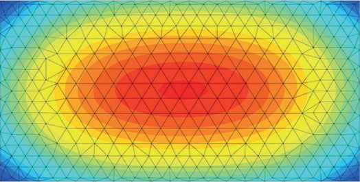
Fig. 17. Deformation of the foundation slab, reinforcement spacing 5x5 m, reinforcement length 9.5 m (max 62.6 mm)
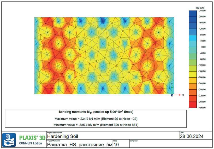
Fig. 18. Moment of foundation slab, reinforcement spacing 5x5 m, reinforcement length 9.5 m (max 385.4 kN/m/m)
MANUFACTURING TECHNOLOGY FOR BUILDING MATERIALS AND PRODUCTS inforcing element: L = 2.5 m, L = 5.5 m, L = 9.50 m. The diameter of the reinforcing element is 300 mm. The optimum spacing between the centers of the compacted zone was chosen to be 2×2 m.
For the final selection of the rational option of the reinforcement element length for this building, it was decided to analyze the results of bending moments and de-formation in the foundation slab (Figures 19–24). The quantification of the results is presented in Table 4.
As shown in Figure 25, as the length of the reinforcement element decreases, the foundation’s settlement increases and the foundation slab’s deformation increases. At small lengths of 2.5–5.5 m, within the compressible thickness, the reinforcing element and the surrounding soil work according to the principle of the method of equal deformations, the value of settlement depends on their components [32]. Experts also recommend that
the equivalent modulus of deformation of the reinforced soil should be considered when evaluating the practical characteristics of the soil mass reinforced with reinforcing elements [33–34]. As the length of the reinforcing element increases, the value of the equivalent modulus of deformation of the reinforced soil increases, effectively reducing the settlement of the reinforced foundation. Increasing the length of the reinforcing element from 2.5 m to 9.5 m reduced the foundation slab deformation by three times and reduced the bending moment by 60% (Table 4).
As a result, the structural solution of the vertically reinforced slab foundation of a multi-storey building: spacing between reinforcing elements 2×2 m, length – 9.5 m, diameter – 300 mm, material – concrete B25. At the same time, the maximum calculated settlement of the slab foundation is S = 3.99 cm. According to the normative documentation for multi-storey buildings with
Ү

Total displacements uz (scaled up 50,0 times) Maximum value = -0,02703 m (Element 4 at Node 32) Minimum value = -0.1046 m (Element 650 at Node 8039)
|
К |
PLAXIS® 3D CONNECT Edition |
Hardening Soil |
23.06.2024 |
||
|
Раскатка HS 2 5M |
|||||
Fig. 19. Deformation of the foundation slab, reinforcement length 2.5 m, (max 104.6 mm)
Table 4. Values of bending moments and deformation of the foundation slab from the length of the reinforcing element
|
Length of reinforcing element, m |
Bending moment, KN/m, |
Deformation of the foundation slab, mm |
|
Without reinforcing element |
476.2 |
124.3 |
|
2.5 |
430.2 |
104.6 |
|
5.5 |
268.9 |
59.81 |
|
9.5 |
197.4 |
39.9 |

CONNECT Edition
PIAXIS9 3D Hardening Soil

Bending moments Mn (scaled up 5,00*1 O'3 times)
Maximum value = 25,23 kN m/m (Element 7 at Node 33) Minimum value = -430,2 kN m/m (Element 733 at Node 8152)
[RNm/m]

Prefect f^rwne
Раскатка HS 2 5M

Fig. 20. Deformation of the foundation slab, reinforcement length 5.5 m (max 59.81 mm)


Total displacements uz (scaled up 50,0 times) Maximum value = -0,01645 m (Element 4 at Node 32) Minimum value = -0,05981 m (Element 650 at Node 8275)
|
PLAXISX3D CONNECT Edition |
Projta tl*scnpt»n Hardening Soil |
DaM 23.06,2024 |
|||
|
№^Kf№nag Раскатка HS 5 5м |
10 |
||||
Fig. 21. Deformation of the foundation slab, reinforcement length 5.5 m (max 59.81 mm)


PLAXIS® 3D
CONNECT Edition
Hardening Soil
Prefect H^ntmt
Раскатка HS 5 5м
28.06.2024
Fig. 22. Foundation slab moment, reinforcement length 5.5 m (max 268.9 kN/m/m)

Fig. 23. Schemes follow the same formatting
MANUFACTURING TECHNOLOGY FOR BUILDING MATERIALS AND PRODUCTS
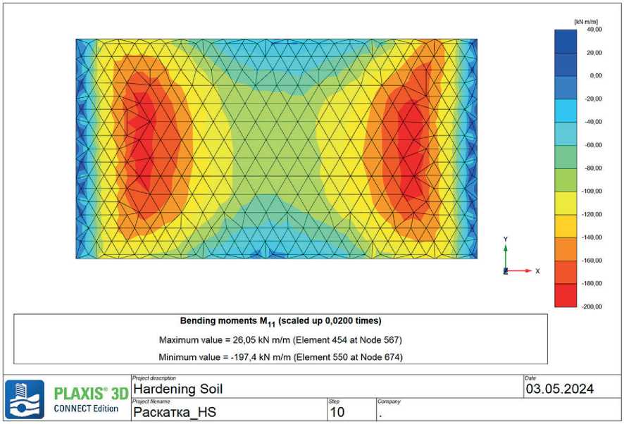
Fig. 24. Foundation. Moment M length of reinforcing element 9.5 m (max 197.4 kN/m/m)
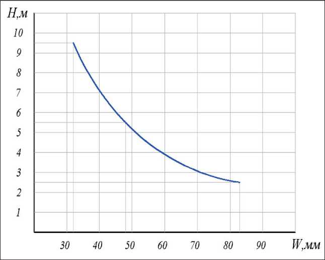
Fig. 25. Graph of the dependence of the slab deformation on the length of the reinforcing element
a fully reinforced concrete frame, the foundation’s limit deformation in settlement is 15 cm. For buildings with foundations in solid slabs, the limit values of average settlements can grow by a factor of 1.5: [S] = 3.99 cm–1.5 = 5.99 cm. Since the maximum design settlement of the slab foundation S = 3.99 cm is less than the limit value of the average settlement [S] = 3.99 cm–1.5 = 5.99 cm, the calculation of the foundation deformations of the slab foundation has been performed successfully.
Increasing the bearing capacity of the foundation is also connected with the process of borehole creation by drilling with a special drilling tip and rolling out. The
MANUFACTURING TECHNOLOGY FOR BUILDING MATERIALS AND PRODUCTS essence is the compaction of the borehole wall with the drill bit during the drilling process. Here, it is essential to consider the increase of soil density around the borehole wall by two times, which effectively affects the resistance of the pile shaft due to lateral friction. Here, it is also necessary to consider the exclusion of the technological gap during the technological pile sinking.
CONCLUSION
The use of rolling equipment in constructing bored vertically reinforcing elements is a promising and reliable method of ensuring the bearing capacity and deformability of the foundation. During rolling, a compacted zone with a diameter larger than the size of the reinforcing element is created, increasing the soil stiffness in the in-ter-element space, which greatly increases the bearing capacity of the foundation.
Reinforcement of the soil foundation with concrete cast-in-place piles enabled to increase the bearing capacity of the foundation and reduce deformability by three times.
The analysis of the stability of geotechnical structures shows that targeted inclusion of reinforcing materials in the soil increases strength, reduces deformability of the foundation, and reduces uneven settlement of the building.
In the presented calculated model, the work of the reinforcement element in the soil is provided by lateral compression and friction forces.
The prospect of further experiments will be to investigate the spatial performance of the system ‘reinforcing element – interelement soil space’ to determine the optimal design solutions for massif reinforcement.
-
1. The calculation and experimental studies conducted made it possible to substantiate the effectiveness of using reinforced foundations on highly compressible soils, with the formation of rigid reinforcing elements with specified geometric dimensions and physical, mechanical, and deformation characteristics.
-
2. The study established that reinforcing the base of a slab foundation effectively is ensured by installing a soil cushion (distribution layer) of sandy or gravelly soil thinner than the slab part of the foundation.
-
3. The calculation results reveal that the design solution for the vertically reinforced base of the slab foundation, specifically the spacing, diameter, and length of the reinforcing elements, must be determined based on the engineering and geological circumstances of the construction site.
-
4. Calculation and experimental studies have revealed the dependence of the length and spacing of reinforcing elements on the depth of the compressible thickness of the weak soil massif. At small lengths of reinforcing elements within the compressi-ble thickness, foundation deformations exceeding the permissible limits are observed. Also, increasing the spacing of reinforcement elements leads to increased deformation in the foundation slab.
-
5. The research findings on vertically reinforcing components on a tangible object allowed for a threefold reduction in deformability and an increase in the bearing capacity of the foundation, which greatly reduced the time and expense involved in building artificial foundations.
-
6. However, it should be noted that the lack of consideration of soil plastic properties in the space between the reinforcing elements allows only a qualitative assessment to identify the need for changes in the design of slab foundations to exclude zones of highstress concentrations.
