Модернизация иркутского радара некогерентного рассеяния

Автор: Кушнарев Д.С., Лебедев В.П., Хахинов В.В., Евстифеев С.Е., Заруднев В.Е.
Журнал: Солнечно-земная физика @solnechno-zemnaya-fizika
Статья в выпуске: 3 т.3, 2017 года.
Бесплатный доступ
Представлены результаты модернизации управляющего и приемно-регистрирующего комплекса Иркутского радара некогерентного рассеяния. Работы были проведены в рамках выполнения и по результатам космических экспериментов «Плазма-Прогресс» и «Радар-Прогресс» с привлечением транспортных грузовых кораблей серии «Прогресс». В результате модернизации повысилась точность радиолокационных измерений низкоорбитальных космических аппаратов, например, при отношении сигнал/шум, равном 10, точность измерений дальности составляет 100-300 м, углов - 1-5 угл. мин.
Радиолокация, иркутский радар некогерентного рассеяния, космические эксперименты "плазма-прогресс" и "радар-прогресс".
Короткий адрес: https://sciup.org/142103655
IDR: 142103655 | УДК: 550.837.76, | DOI: 10.12737/szf-33201708
Modernization of the irkutsk incoherent scatter radar
We present the results of modernization of the Irkutsk Incoherent Scatter Radar’s control and acquisition system. The modernization was carried out using results of space experiments “Plasma-Progress” and “Radar-Progress” involving Progress cargo spacecraft. The modernization has improved the accuracy of radar measurements of low-orbit spacecraft. For example, with a signal-to-noise ratio equal to10, the accuracy of range and angle measurements is 100-300 m and 1-5 arc min.
Текст научной статьи Модернизация иркутского радара некогерентного рассеяния
One of the main tasks of space experiments (SE) Plasma–Progress (2007–2009) [ rus/iss//researches/geophis-13. html; Lebedev et al., 2008; Potekhin et al., 2009] and Radar–Progress (2010– 2015) [ aspx?idE=183; Khakhinov et al., 2013] was to analyze the effect of exhaust jets from liquid propellant engines on the radio image of a low-orbit spacecraft by comparing reflection characteristics of Progress cargo spacecraft having operative and inoperative engines. A distinctive feature of the SE is a weak ionospheric effect of exhaust jets (the amount of exhaust products from 2 to 11 kg).
Reflection characteristics of Progress cargo spacecraft (CS) were measured with the Irkutsk Incoherent Scatter Radar (IISR) [Zherebtsov et al., 2002; Lebedev et al., 2013]. During the SE, IISR’s digital control and acquisition system (DCAS) was upgraded in several stages to improve methods for acquiring and processing the coordinate and reflection characteristics of the spacecraft.
The SE sessions were held during the Progress CS autonomous flight after undocking from the ISS. When the Progress CS was within the field of view of the radar, the onboard liquid propellant engines started. From session to session, the direction of exhaust jet, the direction of solar illumination of exhaust plume, and the direction of jet velocity relative to the geomagnetic field vector varied. Simultaneously with parameters of the rocket exhaust-induced ionospheric disturbances, we recorded background undisturbed values of ionospheric parameters along the sounding path.
1. THE IRKUTSK INCOHERENT SCATTER RADAR
The Irkutsk Incoherent Scatter Radar is a unique scientific instrument in Russia based on the equipment of the radar station Dnepr. IISR is a monostatic pulse radar with frequency scanning. The range of the radar’s operating frequencies is 154–162 MHz; the peak power, achieved with two transmitters, is 2.8 MW; the sounding pulse duration is from 70 to 900 μs; the pulse repetition rate is 24.4 Hz; the antenna gain is ~35 dB. The main difference between IISR and other radars of this type lies in the design features of its antenna.
2. STAGES OF MODERNIZATION OF THE IRKUTSK INCOHERENT SCATTER RADAR 2.1. Features of DCAS modernization until 2008
The progress in diagnostic capabilities of IISR between 2003 and 2008 was facilitated by the radical modernization of the entire system of control, reception, and acquisition devices and signal processing facilities in order to make full use of the radar potential and design features of its antenna. The main task of the modernization was to provide the following radar capabilities:
-
1) measuring parameters of ionospheric plasma simultaneously in several directions to study its spatially inhomogeneous structure;
-
2) simultaneous measurements without amplitude distortions of power signals from SC or coherent echo against weak incoherent scatter signals;
-
3) controlling the shape of the antenna pattern (AP) and making interferometric measurements;
-
4) automatically detecting the presence of coherent signals on the radar scan, providing the possibility of making an automatic decision to change the operating mode;
-
5) increasing spatial resolution and expanding the
vertical range of ionospheric measurements by using optimum sounding signals and eliminating signals reflected from local objects from the radar scan;
-
6) making soft copies of the total volume of raw sounding data to ensure selection of a secondary processing method adequate for changing tasks and environmental conditions;
-
7) processing a large ionosphere and satellite sounding dataset.
Accomplishing the tasks at hand required the development of a new DCAS, which includes
• a multichannel receiver;
• a digital system for synchronizing and generating operating frequencies;
• a system for automatic transmitter phasing;
• a system for recording the shape of a transmitted pulse;
• a high-speed device for acquiring signals and controlling the radar;
• a distributed computer system for secondary processing of sounding data.
2.2. Features of DCAS modernization for the Radar–Progress SE
This DCAS was employed in all experiments conducted with IISR in 2007–2012 [Potekhin et al., 2008].
With the beginning of the first Radar–Progress SE sessions, as well as to solve current problems of monitoring the spacecraft, new requirements to this DCAS were formulated:
-
• the accuracy of matching to the global naviga-tion/timing systems should be no worse than 1 μs;
-
• digital receivers with a reception bandwidth of up to 1 MHz, a dynamic range of 60 dB, a linear and highly stable phase-frequency characteristic of the receiving path in the required reception bandwidth, a programmable gain;
-
• the capability of generating complex sounding signals and their sequences.
To solve these problems in IISR's DCAS, we had to
-
• integrate a high-precision GPS receiver into the control system;
-
• apply modern chips to synthesizers of radio frequencies, which enable us to specify durations, frequencies, and types of manipulation of sounding signals (AM, FM, LFM);
-
• modify the control unit to operate the GPS receiver and new synthesizers;
-
• use modern digital receivers to expand the dynamic range and ensure the linearity of PFC of the receiving path;
-
• eliminate “redundant” analog units such as multipliers by 8 and the receiving unit at the second intermediate frequency;
-
• install a system of online processing of received signals, reflected from the spacecraft, into IISR's computing system.
In the SE sessions in 2011, a new Digital Down Converter (DDC) and a new timing system began to be installed. The digital receiver is a separate system for acquiring radio signals, which is based on up-to-date components and allows us to digitize, demodulate, process, and store received signals in a given frequency band. This system utilized a single-purpose, computer board Insys ADP64Z2APCI and a submodule of digital acquisition ADMDDC416x100M with basic parameters listed in Table 1.
The DDC submodule was connected to the outputs of the receiving unit and acquired a signal at the first intermediate frequency of 18.75 MHz, thus allowing us to discard some analog units and second intermediate frequency. At the same time, the software control of the submodule's parameters enabled us to change IISR's operating modes in a timely and flexible manner.
Table 1
Digital receiver parameters
|
Parameter |
Value |
|
Number of ADC channels |
4 |
|
Number of DDC channels |
4 |
|
ADC capacity |
16 bits |
|
DDC chip type |
Texas Instruments GC5016 |
|
Frequency range of input signals |
2–140 MHz |
|
ADC maximum sampling rate |
105 MHz |
|
Spurious Free Dynamic Range (SFDR) for F =21.4 MHz |
85 dB |
|
Signal/noise ratio (SNR) for F =21.4 MHz |
71 dB |
|
Input impedance |
50 Ohm |
|
Input range |
±0.5 V |
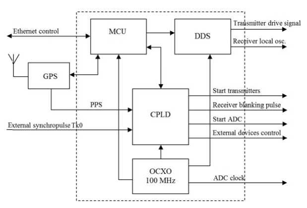
Figure 1 . Flow chart of a new system for synchroniz i ng and forming IISR operating frequencies
The SE observations of different typ e s exploited d ifferent reception bandwidths (from 25 k H z to 1 MH z ) and different gains.
This s y stem through the DDC submodule wa s connected in p arallel with the regular ac q uisition syst e m of DCAS and was used in 2012–2014 o nly to monit o r the spacecraft.
In 2014, the next stage of IISR modernizatio n occurred. A new system for synchronizing and gene r ating operating frequencies was devised a n d implemen t ed. It has the fol l owing capabilities:
-
• gen e rating control synchrosi g nals for all IISR units (start/stop signals of transmitte r s, switching t ubes, receivers);
-
• the source of all signals is a single referen c e oscillator;
-
• for m ing operating frequencies for transm i tters, local oscillators of receivers, and other IISR syste m s;
-
• con t rolling the transmitter pha s ing system;
-
• inte r acting with the control computer vi a the Ethernet interface.
Figure 1 shows a flow chart of a new control system for IISR. Its kernel is a microcontroller unit (MCU) based on a high-speed ARM processor. The unit is de- signed to configure and control the Direct Digital Synthesizers (DDS), Complex Programmable Logic Device (CPLD), to connect with a GPS receiver, and interact with the control computer. Immediately after power-up of this unit, all subsystems are configured to default operating parameters. Then, the connection is established to the control software of the host computer and settings needed for a particular experiment are downloaded. As a channel of control and connection with the control computer, the Ethernet controller and User Datagram Protocol (UDP) are used.
The source of a single refer e nce frequen c y for all the rada r systems wa s a temperatu r e-stabilized q uartz oscillator of 100 MH z (OCXO M33005) with a relative instability of 1.5·1 0 –9 s. The sa m e oscillator is used as a clock frequency s o urce for digi t al IISR recei v ers.
The subsyste m for generat i ng operating frequencies is implemented u sing two A D 9958 synth e sizers produced by Analog Devices; the s e DDS are p rogrammed by M CU and faci l itate generat io n of compli c ated modulate d (FM, LFM) sounding sig n als in the op e rating band of the radar 154–162 MHz f or various e xperiments. The s e synthesizers form het e rodyne freq u encies for IISR’s receivers.
Table 2
Stages of IISR moder n ization
|
Date |
Type of t ransmitted sig n als |
Duration of radar signal, μs |
R eceiver ba n dwidth, kHz |
Sta g es of IISR modernization |
|
2007, Sep t ember |
43-element phase-shift signal |
860 |
100 |
|
|
2008, Feb r uary |
sequence of rectangular and 4 3-element phase-shift signa l s |
|||
|
2008, Sep t ember, 1–3 |
||||
|
2008, Sep t ember, 4–8 |
sequence of rectangular and 13-element phase-shift signa l s |
858 |
50 |
|
|
2009, Feb r uary |
||||
|
2009, Sep t ember |
50 600 |
|||
|
2010, April |
||||
|
2010, August–September |
25 |
|
2011, April |
25 500 |
|||
|
2011, August |
sequence of two 13-element phase-shift signals (at different operating frequencies) transmitted in one sounding pulse |
442+442 |
1000 |
|
|
2012, April 2012, August 2013, April 2013, June |
sequence of two flat signals in one sounding pulse; in the next pulse, a chirp signal is transmitted, 498.891 MHz/s frequency tuning rate |
442+442 902 (LFM) |
8) timing: GPS, 10–6 s accuracy |
|
|
2014, April 2014, July |
sequence of two flat signals in one sounding pulse; in the next pulse, a chirp signal is transmitted; the tuning rate is 407.452 MHz/s |
|
The basic logic of control signal generation is implemented in CPLD. Input signals for it are represented by a clock frequency of 100 MHz from the OCXO oscillator and an external synchropulse Tk0 with a repetition rate of 24.4 Hz. All other service signals for different IISR units are formed from these two signals. The CPLD matrix has internal control registers accessible to MCU, thus facilitating flexible generation of sequences of synchrosignals depending on experimental conditions, for example, a quick shift of the position of the “Start ADC” signal on the time scan of transmission–reception cycles in each sounding pulse to gain information from different vertical ranges. The synchronizing system provides a precise phase matching of all signals to the OCXO reference oscillator.
The synchronizing subsystem with a unified precise time scale is based on a high-stable GPS receiver Trimble Thunderbolt. Connection with this receiver is also established through MCU. Via the serial interface, it gets current date/time, and due to the high-precision pulse per second (PPS) it syncs all the transmission–reception cycles up to 10–6 s. This makes it possible to substantially increase the synchrony of all observation modes in such a complicated experiment as Radar–Progress.
3. IISR OPERATING MODES
The Radar–Progress SE involves two main operating modes of IISR:
• ionospheric observation mode;
• spacecraft monitoring mode.
4. RESULTSOF THE MODERNIZATION
The ionospheric observation mode serves to detect a signal scattered from ionospheric plasma in a vertical range 150–1200 km. Signals are emitted by two phased transmitters with a pulse power of 1.2 MW each. DCAS generates two probing pulses with durations of 700 and 200 μs, one of which is filled with a 5-element Barker code with a spatial resolution of 6 km. The digital receiver and the acquisition system record separate time scans of a received signal in four independent channels with bandwidths of 125 and 250 kHz respectively. Received signals from narrowband channels are used to obtain ion and electron temperatures and plasma drift velocities [Potekhin et al., 2008; Shcherbakov et al., 2015]; signals from broadband channels serve as the basis for constructing vertical electron density profiles of ionospheric plasma [Alsatkin et al., 2015].
The spacecraft monitoring mode involves scanning a specific sector in the IISR AP in order to detect and track an object. In this sector, Progress CS onboard engines are switched on and off. DCAS turns on this mode by the time the CS enters the IISR scanning sector minus DT seconds and turns it off when the CS exits the scanning sector plus DT seconds; DT ranges from 15 to 30 seconds. The scanning area and the number of operating frequencies N (AP azimuths) involved in scanning depend on the geometry of the experiment, i.e. on the area of intersection of the scanning sector and the CS ephemeris. All parameters (time, frequency, waveforms, receiving interval length, ADC and DDC parameters) are calculated in advance and downloaded using configuration files to the DCAS control software.
During all the SEs, simultaneously with IISR upgrading, we tried sounding signals of different types. Table 2 lists stages and types of signals used in a given period. In April 2012, an alternating mode comprising signals of two types was adopted for spacecraft monitoring: two flat (unmodulated) signals and one signal with chirp filling, lasting for 442+442 and 902 microseconds respectively. Rectangular signals allows us to determine the range, radial velocity, and, rather roughly, angles. The chirp signal facilitates a high-precision identification of the antenna azimuth, as well as the range and the antenna elevation angle. The joint use of signals of the two types provides the most complete and accurate set of flight path information.
After being modernized, IISR’s DCAS features the following capabilities.
The programmable logic allows us to flexibly change the operating modes of the radar systems according to the tasks set in the experiments, without creating any new or modified hardware units.
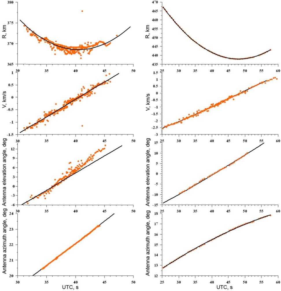
Figure 2 . Measurements of Progress CS (from top t o bottom): ra n ge R , speed V , antenna elev a tion angle, an d azimuth for September 19, 2007 (left), July 26, 2014 ( r ight). The ora n ge color indic a tes measured d ata; the black c olor, calculated data
All the ch a nges can be made in the C P LD firmwar e , and then it be d ownloaded at any time.
The interaction of MCU with DD S , GPS, and C PLD via serial i nterfaces allows us to us e in the futur e any units of o t her manufacturing companies, withou t substantial up g rading of the entire IISR software. On l y the microprog r am for MCU will be modi f ied.
Modern synthesizers in use allow us to reject one stage of multiplication in the subsystem for generating driving signals of transmitters and receiver local oscillators. In the previous version of such a subsystem, source DDS signals (~20 MHz) were multiplied 8 times; in its current version, signals of the operating range 154–162 MHz are multiplied 4 times, thus significantly increas- ing the quality of generated radio signals.
The control c hannel of th e entire syn c hronization system , implem e nted using the standa r d Ethernet equi p ment, exclu d es the need f or any speci a l interfaces and computers. W e can use a ny compute r s with any ope r ating system s to control th e entire IIS R hardware and software syst e m.
Since 2014, a l l SEs with II S R have bee n carried out using the new sy n chronizatio n and control system and the n ew digital receiver. Figur e 2 shows th e differences bet w een obtained path parame t ers of the Pr o gress CS in two sessions of the Radar– P rogress SE: before the DC A S moderniz a tion (Septe mb er 19, 2007, left panel) and after it (July 2 6, 2014, righ t panel).
After the modernization, it became possible to use chirp signals, which can significantly improve the accuracy of range and angle measurements: with a signal-to-noise ratio of 10, the range accuracy is 100–300 m, the angle accuracy is 1–5 arcmin. By comparison, the accuracy of measurements in the experiments until 2010 at the same signal-to-noise ratio was 1.5 km in range and 30–60 arcmin in angles. At present, the modernized DCAS identifies path parameters in real time, whereas before the modernization the processing took a long time and had several stages. The achieved accuracy in measuring path parameters in real time enabled us to solve the problem of pointing the telescope, installed in the Sayan Solar Observatory of ISTP SB RAS, at low-orbit spacecraft, using IISR data.
CONCLUSION
The modernization of IISR’s digital control and acquisition system during the Plasma–Progress and Radar– Progress space experiments made from 2007 to 2015 has improved the accuracy of identification of path parameters of low-orbit spacecraft and has expanded the capabilities of this system for future measurements. The use of the modern hardware components led to the unification of all DCAS units and opened prospects for further modernization of IISR, unique instrument of national significance No. 01-28 included into the worldwide network of radars of this type.
Other results of the Plasma–Progress and RadarProgress SE, obtained with IISR, are reported in [Lebedev et al., 2011; Khakhinov et al., 2012; Borisov et al., 2012; Khakhinov et al., 2012; Korsun et al., 2014].
Список литературы Модернизация иркутского радара некогерентного рассеяния
- Алсаткин С.С., Медведев А.В., Ратовский К.Г. Особенности поведения ионосферы вблизи максимума ионизации по данным Иркутского радара некогерентного рассеяния для низкой и умеренной солнечной активности//Солнечно-земная физика. 2015. Т. 1, № 3, С. 28-36.
- Борисов Б.С., Габдуллин Ф.Ф., Гаркуша В.И. и др. Радиофизические характеристики плазменного окружения низкоорбитальных КА по данным космических экспериментов//Нелинейный мир. 2012. Т. 10, № 10. С. 700-709.
- Жеребцов Г.А., Заворин А.В., Медведев А.В. и др. Иркутский радар некогерентного рассеяния//Радиотехника и электроника. 2002. Т. 47, № 11. С. 1339-1345.
- Корсун А.Г., Куршаков М.Ю., Кушнарев Д.С. и др. Исследование влияния двигателей космических аппаратов на ионосферу//Научное обозрение. 2014. T. 8, № 2. С. 563-571.
- Лебедев В.П., Хахинов В.В., Кушнарев Д.С., Твердохлебова Е.М. Повышение эффективности радиолокационных измерений на Иркутском радаре некогерентного рассеяния//XXVIII Всероссийский симпозиум «Радиолокационное исследование природных сред»: Труды. СПб.: ВКА им. А.Ф. Можайского, 2013. Вып. 10, Т. 1. С. 324-331.
- Потехин А.П., Медведев А.В., Заворин А.В. и др. Развитие диагностических возможностей Иркутского радара некогерентного рассеяния//Космические исследования. 2008. Т. 46, № 4. С. 356-362.
- Хахинов В.В., Потехин А.П., Лебедев В.П. и др. Результаты дистанционного зондирования ионосферных возмущений в активных космических экспериментах «Радар-Прогресс»//Современные проблемы дистанционного зондирования Земли из космоса. 2012. Т. 9, № 3. С. 199-208.
- Хахинов В.В., Потехин А.П., Лебедев В.П. и др. Некоторые результаты активных космических экспериментов «Плазма-Прогресс» и «Радар-Прогресс»//Вестник Сибирского государственного аэрокосмического университета им. акад. М.Ф. Решетнева. 2013. Специальный выпуск 5 (51). С. 160-163.
- Khakhinov V.V., Shpynev B.G., Lebedev V.P., et al. Radiosounding of ionospheric disturbances generated by exhaust streams of the transport spacecraft "Progress" engines//Proc. PIERS. Moscow, Russia. 2012. P. 1168-1171.
- Lebedev V.P., Khakhinov V.V., Gabdullin F.F., et al. Studying the characteristics of the plasma environment at low-orbiting space vehicles by radar methods//Cosmonautics and Rocket Engineering. 2008. V. 50 (1). P. 51-60.
- Lebedev V., Khakhinov V., Potekhin A., et al. Variations of the transport spacecraft "Progress" radar characteristics connected with the orbital maneuvering subsystem run//Proc. XXX URSI General Assembly, HP2.16. Istanbul, Turkey, 2011.
- Potekhin A.P., Khakhinov V.V., Medvedev A.V., et al. Active space experiments with the use of the transport spacecraft "Progress" and Irkutsk IS Radar//Proc. PIERS-2009 "Progress in Electromagnetics Research Symposium". Moscow, Russia, August 18-21, 2009. Moscow, Russia, 2009. P. 217-221.
- Shcherbakov A.A., Medvedev A.V., Kushnarev D.S., et al. Calculation of meridional neutral winds in the middle latitudes from the Irkutsk Incoherent Scatter Radar//J. Geophys. Res.: Space Phys. 2015. V. 120, N 12. P. 10851-10863. DOI: 10.1002/2015JA021678.
- URL: http://www.energia.ru/rus/iss//researches/geophis-13.html (дата обращения 18 мая 2017 г.).
- URL: http://knts.tsniimash.ru/ru/site/Experiment_q.aspx? idE=183 (дата обращения 18 мая 2017 г.).
