Modified Approach for Harmonic Reduction in Transmission System Using 48-pulse UPFC Employing Series Zig-Zag Primary and Y-Y Secondary Transformer

Author: Ragini Malviya, Rakesh Kumar Saxena
Journal: International Journal of Intelligent Systems and Applications(IJISA) @ijisa
Article in issue: 11 vol.5, 2013.
Free access
In this paper THD (Total Harmonic Distortion) is analysed and compared by using UPFC in a multi-line transmission system of 500 KV having 5-buses in two different arrangements. The UPFC converters are arranged as a Diode Clamped multilevel Converter (DCMLC) that leads to the cost reduction as compared with other multi-level converters. The comparison has been done by both series zig-zag/2Y-2Δ and series zig-zag/4Y transformer configuration for 48-pulses GTO based diode clamped converter. The THD is reduced to 42.59% and 58.82% of input waveform at bus B2 by using series zig-zag/4Y transformer configuration. This transformer converter configuration also reduces the difficulty of designing the transformer winding ratio. For calculation of THD, FFT analysis is carried out using MATLAB.
GTO Based Diode Clamped Inverter, FFT Algorithm, Harmonic Distortion, FACTS Devices, Unified Power Flow Controller
Short address: https://sciup.org/15010492
IDR: 15010492
Text of the scientific article Modified Approach for Harmonic Reduction in Transmission System Using 48-pulse UPFC Employing Series Zig-Zag Primary and Y-Y Secondary Transformer
Published Online October 2013 in MECS
The UPFC is a device, which can control simultaneously all the three parameters of line power flow which are line impedance, voltage and phase angle [1-2]. It improves terminal voltage regulation, series capacitor compensation and transmission angle regulation [3]. The UPFC is made out of two voltagesource converters (VSCs) i.e static compensator (SATACOM) and and a static synchronous series compensator (SSSC) with semiconductor devices having turn-off capability, sharing a common DC capacitor and connected to a power system through coupling transformers as shown in fig 1 [4].
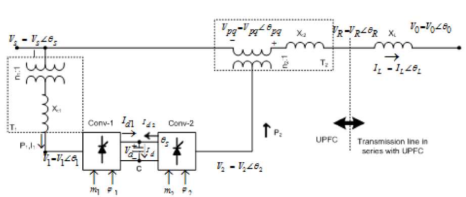
Fig. 1: Implementation of UPFC in transmission line
The shunt converter is primarily used to provide the real power demand of the series converter at the common DC link terminal from the AC power system. It can also generate or absorb reactive power at its AC terminal, which is independent of the active power transfer to (or from) the DC terminal [5-6]. The series converter is used to generate a voltage at the fundamental frequency with variable amplitude and phase angle, which is added to the AC transmission line by the series connected boosting transformer. The inverter output voltage injected in series with the line can be used for direct voltage control, series compensation, phase shifting, and their combinations. This voltage source can internally generate or absorb all the reactive power required by the different type of controls applied and transfers active power at its DC terminal as depicted in figure 1.
This paper deals with the DCML multilevel converter model, which is a 48-pulse (three levels) voltage source converter that helps to exploits the principle of harmonic neutralization in various input waveforms. It consists of three phase, three-level converter and four phase shifting transformers. In this 48-pulse DCML converter, dc bus V dc is connected to four three phase converter. The four voltage generated by the converter are applied to secondary windings of four zig-zag phase-shifting transformers connected in 4 Y. The four transformers primary windings are connected in series and the converter pulse are phase shifted so that the four voltage fundamental components sum in phase with primary side [7].
The paper is organized in 5 sections. The 48-pulse GTO based DCML converter emphasizes briefly in section 2. The concept of 48-pulse UPFC model was suggested by El. Moursi et.al in year (2005) is also described in the section 2 which is modified in this paper and explained in section 3 part A. This paper also explains about control strategy for active and reactive power flow control in a 5-bus interconnected system. The UPFC of 500KV, 100MVA is implemented in a transmission system of (500KV, 5 buses) having series zig-zag primary and 4Y secondary of transformer configuration for 48-pulse GTO based diode-clamped multilevel converter. This model is briefly discussed in section 3 part B. The simulation result and the comparison among the previous and proposed model is discussed in section 4. Finally in section 5, the conclusion after the comparison among the previous model i.e series zig-zag/2Y-2Δ GTO based 48-pulse DCML converter and the modified model i.e zig-zag/4Y GTO based 48-pulse DCML converter is presented.
-
II. 48-pulse GTO based Diode Clamped Multilevel Converter (DCMLC)
As compared with the other multilevel converters like cascade and flying capacitor converter DCMLI as shown in figure 2[8] is preferred to configure UPFC converter as it is an interface between the high voltage DC and AC high voltage transmission line[9] . It also shares a common DC bus for all the three phases which not only minimizes the capacitance requirements but also uses back-to-back interconnection, practically such as UPFC. The 1-phase of 5-level converter is shown in figure 2.
V 5
E 5
C1
D a1
V 4
D a2
E 5
C 2
V 3
E 5
C 3


D a3
D’ a1
D’ a2
Н4-
D’ a3
S a1
S a2
S a3
S a4
S’ a1
S’ a2
S’ a3

D 4
D 3
D 2
D 1
D- 1
D- 2
D- 3
v d
V 2
E 5
C 4
S’ a4
D- 4
V 1 =0
Fig. 2: 1-phase of 5-level DCML converter
The 48-pulse converter can be used in high-voltage high-power applications without any AC filters due to low harmonic distortion content on the AC side. The output voltage would have 48n±1, where n=1, 2,… i.e., 47th, 49th, 95th, 97th,….harmonics with typical magnitudes (1/47th, 1/49th, 1/95th, 1/97th,…. ), respectively with respect to the fundamental AC voltage. The operation of 48-pulse with eight 6-pulse groups, with one set of transformer of one 24-pulse converter phase shifted from the other by ±7.5 degrees [1] is used here in order to reduce harmonics as shown in figure 3. Using a symmetrical shift criterion, 7.5° phase shift are provided in following way: [7]
-
i) phase-shift winding with -3.75° on the two coupling transformers of one 24-pulse converter.
-
ii) phase-shift winding with +3.75° on the other two coupling transformers of one 24-pulse converter
In this paper the Diode –Clamped 3-level 48-pulse GTO based converters as UPFC is coupled with a zigzag transformer having phase shift of 7.5° with different configuration. These configurations are based on the converter arrangement with transformers. It is depicted as
-
1) Series zig-zag / 2Y-2Δ transformer configuration for 48-pulse GTO based DCML converter as shown in figure 4 and simulation model shown in figure 3.
-
2) Series zig-zag/4Y transformer configuration for 48-pulse GTO based DCML converter shown in figure 5 and simulation model in figure 6.
The comparison has been done between these two above configuration based on THD analysis and their design purpose.
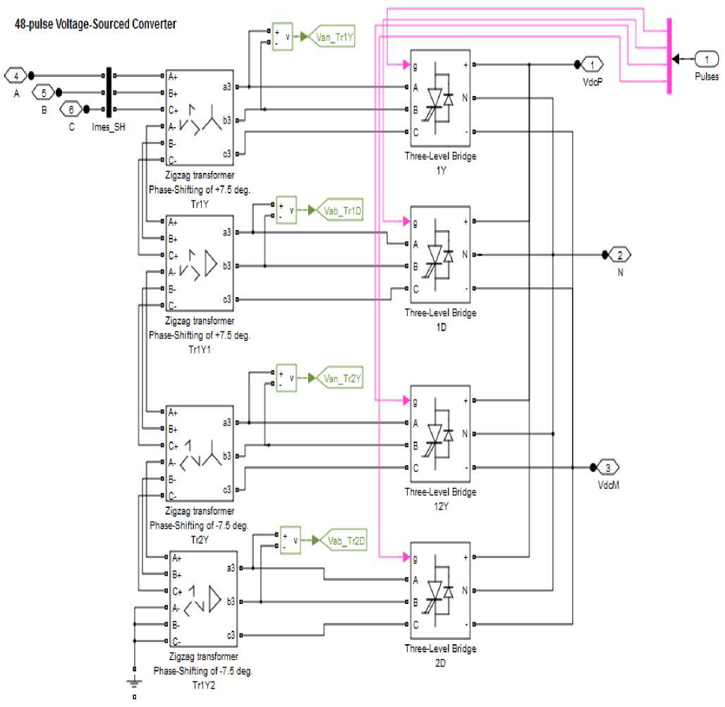
Fig. 3: Simulation Model of 48-pulse 3-level GTO based diode clamped multi-level Converter with series primary-zig-zag/2Y-2Δ secondary transformer
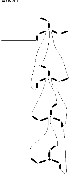
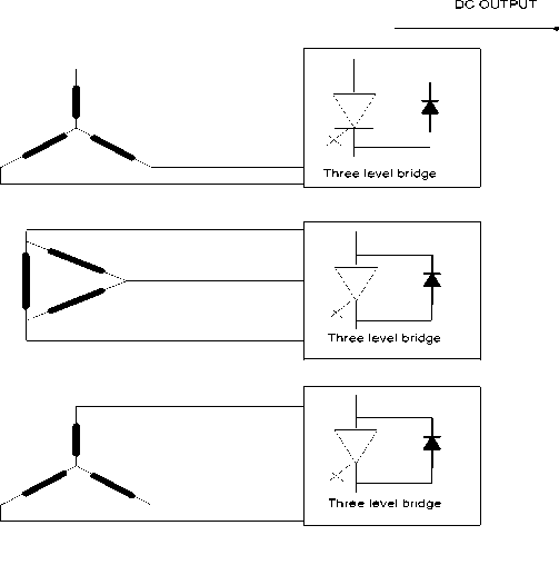
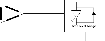
Fig. 4: 48-pulse Converter with zigzag /2Y-2Δ arrangement
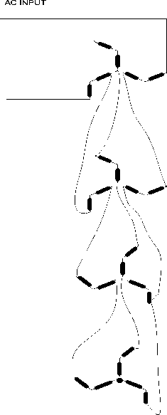
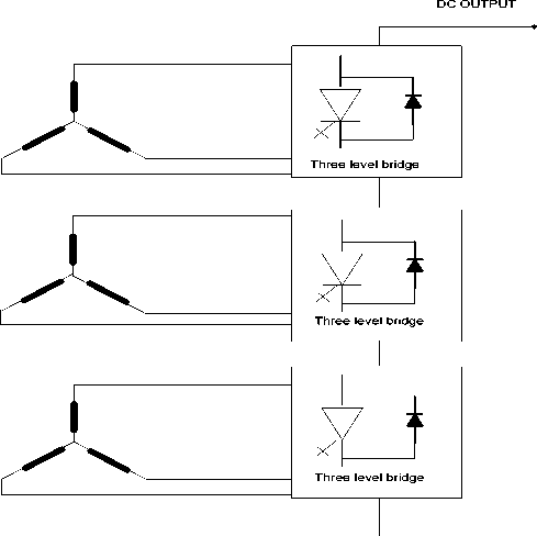
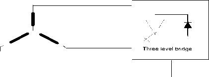
Fig. 5:48-pulse Converter with zigzag /4Yarrangement
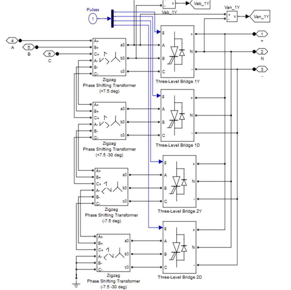
Fig. 6: Simulation Model of 48-pulse 3-level GTO based diode clamped multi-level Converter with series primary-zig-zag/4Y secondary transformer
2.1 Total Harmonic Distortion
A non-linear system produces harmonics of an input sine wave, the harmonics consisting of sine waves with frequencies which are multiple of the fundamental of the input signal. Total Harmonic Distortion (THD) is measured in terms of the harmonic content of the wave as
THD = 4 D^ 2 + D 3 2 + D 42.....x 100
4 E 4 + E 3 + E 4 2 +
E 1
x 100
Thd [ ^ ( Harmonics ) 2 ] 1/2
Fundamental
Where Dn (n=2,3,4_) distortion of n th harmonic and E n represents the amplitude of nth harmonic. E 1 is the amplitude of fundamental.
THD о /о = DD+DD+DD.x
4 E22 + E32 + E42 +
= ^---3---4x
E 1
By using the above equations THD is calculated in MATLAB software by using FFT Analysis.
-
III. Description of Modified Simulation Model
-
3.1 Simulation Model of 48-pulse 3-level GTO based Diode-clamped Converter:
-
-
3.2 Simulation model of a 5-buses transmission system with UPFC (48-pulse GTO based DCMLC):
The four 3-phase, 3-level, converters and four zigzag phase-shifting transformers in a 48-pulse square wave GTO based DCML converter with series primary-zig-zag/4Y secondary transformer (as shown in figure 6) helps to neutralize the harmonic in waveforms V i n j and I abc .
UPFC of 500 KV, 100MVA rating is used to control the power flow in a 500 KV multi-line transmission system. The UPFC is located at the left end of 75 km line L 2 named as L 2 _75 km, between the 500kV buses B 1 and B 2 , is used to control the active and reactive powers flowing through bus B 2 , while controlling voltage at bus B 1 as shown in figure 7. The active power P, reactive power Q flow at bus B 2 after the power flow control by UPFC is examined.
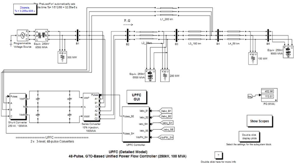
Fig. 7: Simulation model of 48-pulse GTO-based UPFC (500 KV, 100MVA)
-
IV. Simulation Results and Discussion
-
4.1 Simulation of 48-pulse 3-level GTO based DCML Converter with Series Primary-zig-zag/4Y Secondary Transformer
-
A 48-pulse 3-level GTO based DCML converter with series primary-zig-zag/4Y secondary transformer shown in figure 6 is simulated. Voltages generated by the converter (Va b c), load currents (Ia b c), phase-neutral voltage (Van) and phase-phase voltage (Va b ) of one of the four converters is shown in figure 8. When the inverter is operating at no load, the three (3-phase) 48-step voltage waveforms can be observed. When the load is switched on the voltage becomes smoother because harmonics are filtered by the transformer leakage reactance’s without the use of any external ac filters with the help of DCML converter [8]. Table 1
shows Active power P and reactive power Q flows at bus B 2 in the given simulation model.
Table 1: Comparison Of P and Q flow at bus B 2 in two different configurations (2Y-2Δ/ 4YSecondaries)
|
P&Q at bus B 2 Controller |
P(MVA) |
Q(MVA) |
|
System With UPFC with series zig-zag/2Y-2Δ transformer Configuration (initial work) |
910.61 |
63.09 |
|
System With UPFC with series zig-zag/4Y transformer Configuration (present work) |
911.87 |
63.79 |
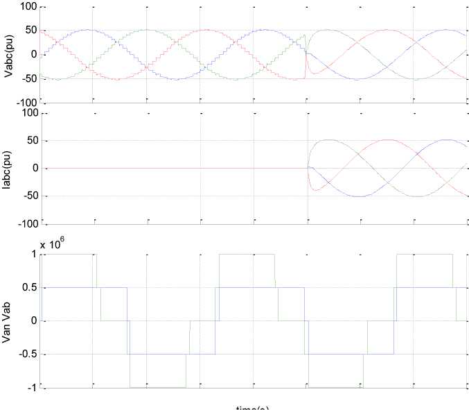
Fig. 8: Simulation waveform of 48-pulse 3-level GTO based diode clamped Converter (w.r.t. figure.6)
-
4.2 FFT analysis for THD of Vinj (injected voltage) and Iabc (current) at bus B2 in series zigzag-2Y-2Δ/ 4Y.
For THD calculat on, FFT analysis in MATLAB/SIMULINK ha been done. This analysis is done for the injected voltage V inj and line current I abc at bus B 2 .
The parameters of FFT window are:
Start time: 0.6, No. of cycles: 2, Fundamental
Frequency: 50 Hz, Max. Frequency: 2000 Hz
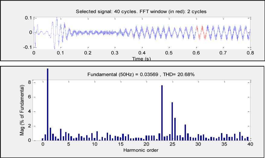
Fig. 9: FFT Analysis for injected voltage V inj at bus B 2 by using series zig-zag/2Y-2Δ transformer configuration
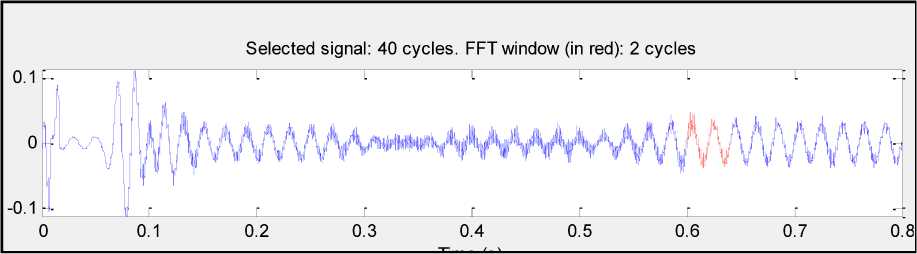
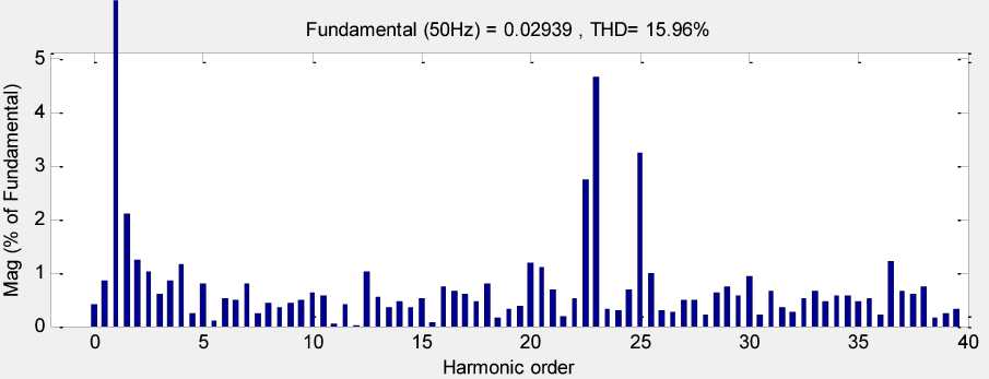
Fig.10: FFT Analysis for injected voltage V inj at bus B 2 by using series zig-zag/4Ytransformer configuration
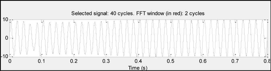
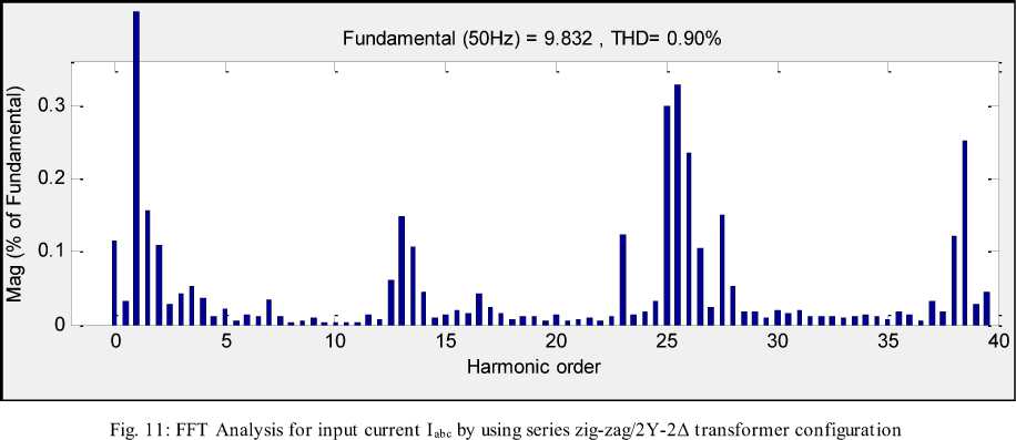
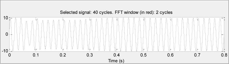
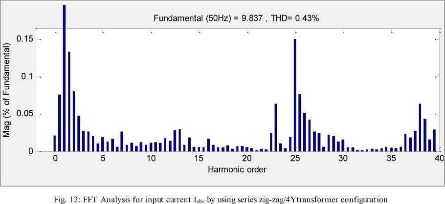
With reference to figure 9, 10,11 and 12 the THD comparison is done between 2Y-2Δ and 4Y configuration and discussed in Table 2.
Table 2: THD Comparison at two different configuration (2Y-2Δ)/ 4YSecondries
|
Zigzag-star delta |
Zigzag-star |
Decrease of THD |
|||
|
Fundamental Freq.(Hz) |
THD % |
Fundamental Freq.(Hz) |
THD% |
||
|
V inj (pu) |
.03547 |
22.61 |
0.2949 |
12.98 |
42.59% |
|
I abc (pu) |
9.821 |
0.85 |
9.833 |
0.35 |
58.82% |
As analysed the THD of Voltage injection in transmission line by SSSC is reduced to 42.59% and the line current I abc at bus B 2 is also reduced to 58.82% by using series zig-zag/4Y configuration than by zig-zag/2Y-2Δ configuration.
Also the effort of designing the zigzag primary and delta secondary (series zig-zag/2Y-2Δ) having phase shift of 30° is reduced and become easier by the zigzag primary and star secondary (series zig-zag/4Y). By using 48-pulse GTO based Diode clamped multilevel converter in UPFC the extra cost of AC filters is reduced as there is no need of these filters as the harmonics are neutralized itself with the help of transformer leakage reactance.
-
V. Conclusion
In this paper the proposed technique of adding the UPFC converter with different transformer configuration that is series zig-zag/4Y transformer configuration having phase shift of +7.5° instead of series zig-zag/2Y-2Δ in the multi- line transmission of 5-bus system is analysed and compared that though the active and reactive power flow is maintained same in both the cases but the (Total Harmonic Distortion) THD is comparatively improved. In short the paper concludes:
THD% is reduced by increasing the power transmission efficiency by using series zig-zag -4Y secondary transformer with converter configuration.
Effort of designing the turn ratio of transformer is reduced by using same arrangement.
DCMLC reduces the need of AC filters as it produces low harmonic distortion content in voltage and current.
References Modified Approach for Harmonic Reduction in Transmission System Using 48-pulse UPFC Employing Series Zig-Zag Primary and Y-Y Secondary Transformer
- N. G. Hingorani and L. Gyugyi, Understanding FACTS, Concepts, and Technology of Flexible AC Transmission Systems. Piscataway, NJ: IEEE Press, 2000.
- Gyuygi L.,"Unified power flow controller Concept for Flexible AC Transmission Systems”, IEEE Proceeding, vol.-139, no.-4, pp.323-331, July 1992
- Paserba, John J. "How FACTS controllers-benefit AC transmission systems."Transmission and Distribution Conference and Exposition, 2003 IEEE PES. Vol. 3. IEEE, 2003
- Huang, Zhengyu, et al. "Application of unified power flow controller in interconnected power systems-modeling, interface, control strategy, and case study." Power Systems, IEEE Transactions on 15.2 (2000): 817-824.
- Chengaiah, C., and R. V. S. Satyanarayana. "Power flow assessment in transmission lines using Simulink Model with UPFC." Computing, Electronics and Electrical Technologies (ICCEET), 2012 International Conference on. IEEE, 2012.
- Gyugyi L., Rietman L.R. and EdrisA. “UPFC: A New Approach to Power Transmission Control”, IEEE Transactions on Power Delivery, vol.-10, no.-2, pp. 1085- 1097, April 1995.
- El. Moursi, M. S., and A. M. Sharaf., "Novel controllers for the 48-pulse VSC STATCOM and SSSC for voltage regulation and reactive power compensation."Power Systems, IEEE Transactions on 20.4 (2005): 1985-1997.
- S. Kouro, M. Malinowski, K. Gopakumar, J. Pou, L. G.Franquelo, Wu ,J.Rodriguez,M.A.Perez,and J. I. Leon, “Recent advances and industrial applications of multilevel converters,” IEEE Trans.Ind. Electron., vol. 57,no. 8, pp. 2553–2580, Aug. 2010.
- J. S. Lai, F. Z. Peng, “Multilevel Converters - A New Breed of Power Converters,” IEEE Transactions on Industry Applications, vol. 32, no. 3, May 1996, pp. 509-517
- Keri A.J.F., Mehraban A.S., Elriachy A., Lombard X. and Edris A., “A Unified Power Flow Controller (UPFC): Modelling and Analysis”, IEEE Transactions on Power Delivery, vol.-14, no.-2, pp. 648-654, April 1999.
- Soto-Sanchez, Diego E., and Tim C. Green. "Voltage balance and control in a multi-level unified power flow controller." Power Delivery, IEEE Transactions on16.4 (2001): 732-738.
