Modified Binary Exponential Backoff Algorithm to Minimize Mobiles Communication Time

Author: Ibrahim Sayed Ahmad, Ali Kalakech, Seifedine Kadry
Journal: International Journal of Information Technology and Computer Science(IJITCS) @ijitcs
Article in issue: 3 Vol. 6, 2014.
Free access
The field of Wireless Local Area Networks (LANs) is expanding rapidly as a result of advances in digital communications, portable computers, and semiconductor technology. The early adopters of this technology have primarily been vertical application that places a premium on the mobility offered by such systems. Binary Exponential Backoff (BEB) refers to a collision resolution mechanism used in random access MAC protocols. This algorithm is used in Ethernet (IEEE 802.3) wired LANs. In Ethernet networks, this algorithm is commonly used to schedule retransmissions after collisions. The paper’s goal is to minimize the time transmission cycle of the information between mobiles moving in a Wi-Fi by changing the BEB algorithm. The Protocol CSMA / CA manage access to the radio channel by performing an arbitration based on time. This causes many problems in relation to time transmission between mobiles moving in a cell 802.11. what we have done show that the protocol using CSMA / CA access time believed rapidly when the number of stations and / or the network load increases or other circumstances affects the network..
Mobile Communicastions, CSMA/CA, Binary Exponential Backoff Algorithm
Short address: https://sciup.org/15012056
IDR: 15012056
Text of the scientific article Modified Binary Exponential Backoff Algorithm to Minimize Mobiles Communication Time
Published Online February 2014 in MECS
In wireless networks, computers are connected and communicate with each other not by a visible medium, but by emissions of electromagnetic energy in the air. The most widely used transmission support is radio waves. Wireless transmissions utilize the microwave specter: the available frequencies are situated around the 2.4 GHz ISM (Industrial, Scientific and Medical) band for a bandwidth of about 83 MHz, and around the 5 GHz U-NII (Unlicensed-National Information Infrastructure) band for a bandwidth of about 300 MHz divided into two parts. The exact frequency allocations are set by laws in the different countries; the same laws also regulate the maximum allotted transmission power and location (indoor, outdoor). Such a wireless radio network has a range of about 10–100 meters to 10 Km per machine, depending on the emission power, the data rate, the frequency, and the type of antenna used. Many different models of antenna can be employed: omnis (omni-directional antennas), sector antennas (directional antennas), yagis, parabolic dishes, or waveguides (cantennas). The other type of transmission support is the infrared. Infrared rays cannot penetrate opaque materials and have a smaller range of about 10 meters. For these reasons, infrared technology is mostly used for small devices in WPANs (Wireless Personal Area Networks), for instance to connect a PDA to a laptop inside a room [1].
-
II. WLAN Standards
There are presently three main standards [2] for wireless networks: the IEEE 802.11 family, HiperLAN, and Bluetooth.
IEEE 802.11
IEEE 802.11 is a standard issued by the IEEE (Institute of Electrical and Electronics Engineers). From the point of view of the physical layer, it defines three non-interoperable techniques: IEEE 802.11 FHSS (Frequency Hopping Spread Spectrum) and IEEE 802.11 DSSS (Direct Sequence Spread Spectrum), which use both the radio medium at 2.4 GHz, and IEEE 802.11 IR (InfraRed). The achieved data rate is 1–2
Mbps. This specification has given birth to a family of other standards:
HiperLAN
HiperLAN (High Performance Radio LAN) is a standard issued by the ETSI (European Telecommunications Standard Institute), and a competitor of IEEE 802.11. It defines two kinds of networks:
Bluetooth
Bluetooth is a standard designed by a consortium of private companies such as Agere, Ericsson, IBM, Intel, Microsoft, Motorola, Nokia and Toshiba. Bluetooth operates in the 2.4 GHz band using FHSS and has a short range of action of about 10 meters. For such characteristics and its low cost, Bluetooth is fit for small WPANs and is also employed to connect peripherals such as keyboards, printers, or mobile phone headsets. Bluetooth radio technology works in a master-slave fashion, and each device can operate as master or as slave. Communications are organized in small networks called piconets , each piconet being composed of a master and 1–7 active slaves. Multiple piconets can overlap to form a scatternet .
-
III. WLAN Architecture
A wireless network [3] can be structured to function in either BSS (Basic Service Set) or IBSS (Independent Basic Service Set) mode. The two modes affect the topology and the mobility capabilities of the machines ( nodes ) that compose the network.
BSS mode
In BSS mode, also called infrastructure mode , a number of mobile nodes are wirelessly connected to a non-mobile Access Point (AP), as in (Figure 2.4). Nodes communicate via the AP, which may also provide connectivity with an external wired network e.g. the Internet. Several BSS networks may be joined to form an ESS (Extended Service Set).
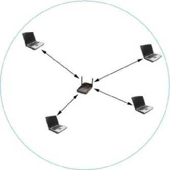
Fig. 1: BSS mode: an Access Point and its network cell
IBSS mode
The IBSS mode, also called peer to peer or ad hoc mode , allows nodes to communicate directly (point-to-point) without the need for an AP, as in (Figure 2.5). There is no fixed infrastructure. Nodes need to be in range with each other in order to communicate.
-
IV. Binary Exponential Backoff
Exponential Backoff is an algorithm that uses feedback to multiplicatively decrease the rate of some process, in order to gradually find an acceptable rate. In a variety of computer networks, binary exponential backoff or truncated binary exponential backoff refers to an algorithm used to space out repeated retransmissions of the same block of data, often as part of network congestion avoidance. Examples are the retransmission of frames in carrier sense multiple access with collision avoidance (CSMA/CA) and carrier sense multiple access with collision detection (CSMA/CD) networks. For instance, in the CSMA/CD: (i) If a collision is detected during transmission of a packet, the node immediately ceases transmission and it transmits jamming signal for a brief duration to ensure that all stations know that collision has occurred. (ii) After transmitting the jamming signal, the node waits for a random amount of time and then transmission is resumed. The random delay ensures that the nodes, which were involved in the collision, are not likely to have a collision at the time of retransmissions. To achieve stability in the back off scheme, the BEB algorithm is used. A node will attempt to transmit repeatedly in the face of repeated collisions, but after each collision, the mean value of the random delay is doubled. After 15 retries (excluding the original try), the unlucky packet is discarded and the node reports an error. A flowchart representing the binary exponential back off algorithm is given in Fig. 2
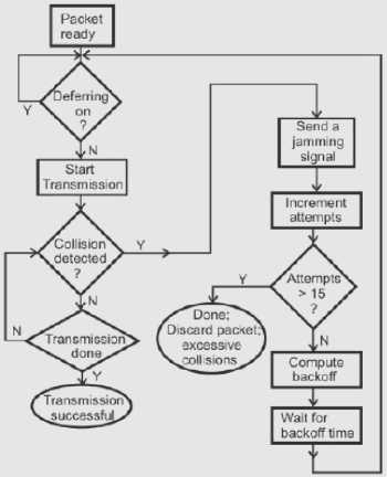
Fig. 2: Binary exponential back off algorithm used in CSMA/CD
-
V. Modified BEB Algorithm and Tools Used
In this section, we will present tools used in our simulation and the implementation of the changed BEB algorithm.
NS2 Simulator
Our simulation is done on NS2. Network simulator 2 or NS2 is an object-oriented discrete event allows us to study the design and protocols for computer networks. It offers various facilities for simulation of the protocols based on TCP, UDP, routing and multi-distribution (broadcast and multicast) in the (wired or wireless) networks. This simulator is a free open source. NS2 is developed in C++ which is a part of the VINT project (Virtual InterNetwork Testbed) is a joint effort led by the University of Berkeley, USC / ISI (University of Southern California's Information Sciences Institute), the LBL (Lawrence Berkeley National Laboratory) and Xerox PARC. It is supported by DARPA (Defense Advanced Research Projects Agency). It uses IU OTCL interpret. Through this language, the user can describe conditions of the simulation: network topology, selected from a lot of physical links, used protocols, communications done, etc.. The user can also create new objects in C++ and use them in NS by instantiations with OTCL, the two languages C++ and OTCL have both very close hierarchies to each other. In NS2 several libraries are available and there are some specific needs for simulation of wireless network and "multicast" communication [4-8]. In our work we use NS2 for its flexibility and the availability of its code [Ben07].
Communication entity in NS2
The node (communicating entity) is the basic element of our model. A node in NS2 is a class defined in OTCL which has three entities containing: the classifier, the link and the agent.
The classifier
The function of a node of the fields is examined by received packet, and more specifically, the source address and destination address. According to contention losses, the node sends the packet on its outgoing interfaces (Fig. 3). In NS2, then this is performed by an object called "Classifier". There are several types of classification that are used for different purposes:
-
- "Address classifiers" is used to treat with unicast packets, and its role is directly to select packets addresses, direct the node, and select the link to the next node.
-
- "Port classifier" its role is to select the agent to the packet which is intended.
-
- "Multicast classifier" is used to classify multicast packets.
The link
It is used to connect the nodes by each other (Fig. 3). A link is defined by several parameters including: bandwidth, entry point, the lifetime of each packet, etc.. NS2 has several types of links, so we can distinguish unidirectional links from bidirectional links and wired links to wireless networks model without sound.
The Agent
Agents represent endpoints where packets in network layer are constructed and consumed. These agents are the third component of the node. In NS2, the agent's role is to provide the destination address; its function is to generate the packets and the interface to the application class (Fig. 3).
In NS2 there are several types of agents, each has a specifying role:
-
- TCP agent: for emitting TCP traffic
-
- UDP agent: for emitting UDP traffic
-
- TCPSink agent: for the receipt of TCP traffic
-
- NULL Agent for receiving UDP packets.
Figure III.1 shows the Existing entities in a node and the links between ITS entities.
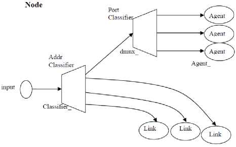
Fig. 3: Diagram of a node in NS2
TCL Language
Tcl (originally from "Tool Command Language", but conventionally spelled "Tcl" rather than "TCL"; pronounced as "tickle" or "tee-see-ell") is ascripting language created by John Ousterhout. Originally "born out of frustration", according to the author, with programmers devising their own languages intended to be embedded into applications, Tcl gained acceptance on its own. It is commonly used for rapid prototyping, scripted applications, GUIs and testing. Tcl is used on embedded systems platforms, both in its full form and in several other small-footprint versions.
AWK Language
The AWK utility is an interpreted programming language typically used as a data extraction and reporting tool. It is a standard feature of most Unix-like operating systems. AWK was created at Bell Labs in the 1970s, and its name is derived from the family names of its authors –Alfred Aho, Peter Weinberger, and Brian Kernighan.
AWK uses a data-driven scripting language consisting of a set of actions to be taken against textual data (either in files or data streams) for the purpose of producing formatted reports. The language extensively uses the string data type, associative arrays (that is, arrays indexed by key strings), and regular expressions.
-
VI. Simulations
Configuration of communicating entities
Configuration of access point
The base station is configured as follows [9-10] (Fig. 4)
$ Ns_ node-config-adhocRouting DSDV
-
• llType-LL / / LL layertype
-
• macType Mac/802_11 \ / / type of the MAC layer
-
• IfqLen 800 \ / / length of the tail
-
• antType Antenna / OmniAntenna \ / / type of antenna
-
• phyType Phy / WirelessPhy \ / / type of physical layer
-
• channelType Channel / WirelessChannel \ / / type of channel
-
• wiredRouting ON \ / / Wired link with other AP's.
In this list we find the basic configurations of the AP. (Type of MAC and physical layer, antenna type...). Figure 4 describes entities used for the AP (agents, links, and classifiers).
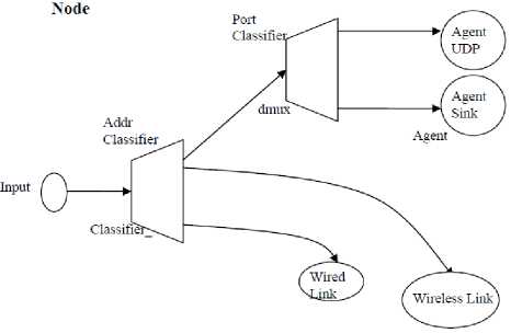
Fig. 4: Figure of base station
Configuration of mobile nodes
The nodes are moving in the Mi cell base station where each node has a unicast address and exchange packets with other mobile station through the base station. In each node there exist a single wireless link but there are two agents (Fig. 5):
-
• An agent to send UDP packets (UDP Because in Our case, we use UDP only)
-
• A null Agent to Receive UDP packets.
These nodes operates in the cell of an access point to which they are attached as shown in Fig 5.
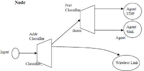
Fig. 5: Diagram of the mobile node
General parameters
The general parameters of this simulation are given in (table 4.1). These parameters for the simulation model are compatible with the measure made.
Table 1: Simulation Parameters
|
CBR Packet Size |
210 bytes |
|
CWMin |
31 ms |
|
CWMax |
1023 ms |
|
SIFS |
0.000010 s |
|
SlotTime |
0.000020 s |
|
CBR rate |
448Kb |
Modeling the methods of Back-off
We will now describe the numerical experiments to adjust the simulation parameters “a” and “b” of the back-off algorithm.
The purpose of this simulation is to study the effect of the load (by changing the number of mobiles) on the transmission time for different values of parameters: “a” and “b”. Our approach is based on cooperation involving the mobiles in the cell, by pairs, and each pair in the cell transmits CBR traffic to other one during a specified time.
Our simulation protocol is the following: We will evaluate the changes in throughput and end to end delay while changing “a” and “b” and the number of nodes in the cell. To increase the cell load, we increase the number of mobiles in introducing new pairs (the mobile communicates with other in pairs), each forming a cooperation group. In the example in (Figure 6) it is pair M5 - M6. For each simulation we vary the values of “a” and “b”. All these mobiles broadcast via the AP (in pairs) according to NS2 simulation parameters mentioned above.
If D is the transmission delay between mobile references, it can be defined as time between sending the message (Temis) and corresponding time to receive the message by the mobile receiver Trec: D= Max(Trec - Temis )
It should be noted that this simulation will help us to find the optimal values of “a” and “b” by changing the Back-off algorithm. The figure below describes our work
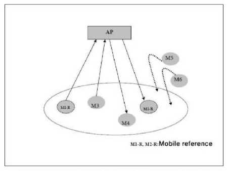
Fig. 6: Principle of simulation used to assess the changed Back-off
Implementation of the modified BEB
In fact the back-off algorithm BEB is implemented in standard NS2. To implement our "modified" algorithm of Back-off algorithm it is sufficient to act on some files in the hierarchy of NS2 MAC layer. We show this hierarchy in the (Figure 7).
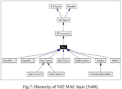
After the study of this hierarchy, we decided to modify the code in C++ functions included in in the following files:
-
• tcl/lan/ns-mac.tcl.
-
• tcl/lib/ns-lib.tcl.
-
• Mac/mac-802_11.h.
-
• Mac/mac-802_11.cc.
-
• tcl/lib/ns-default.tcl.
We want to change the formula of Back-off as follows:
On failure of transmission: CW = min (a.CW, CWmax) and each successful transmission, we decrement the value of CW by value b. CW = max (CW-b, CWmin)
In case of transmission failure, we modified the inc_cw() function by setting CW=min(a* CW,CWmax), a is initialized with a value taken from the interval [1,3].
Original Function:
inline void inc_cw()
{ cw_ = (cw_ << 1) + 1; if(cw_> phymib_.getCWMax())
cw_= phymib_.getCWMax();
}
Modified one:
inline void inc_cw()
}
In case of successful transmission, we modified the rst_cw() method by setting CW=max(CWmin, CW-b) instead of CW = CWmin.
Original Function:
inline void rst_cw()
{ cw_ = phymib_.getCWMin();
}
Modified Function:
inline void rst_cw()
Scenario of simulation
We calculate the average transmission time between all mobiles during a time interval T = 120s for which the cell load remains constant.
To find the best values of “a” and “b”, we vary b in the interval [0, 10] stepping 1 each time and for each b, value of a varies in interval [1,3] stepping 0.1 each time.
The results obtained at the end of the simulations corresponding to different values of “a” and “b” will allow us to choose their optimal values. The optimum means here leading the minimum transmission delay, and maximum throughput.
The following flowchart (Figure 8) describes the scenario simulation and the increment of “a” and “b”.
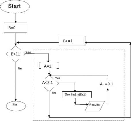
Fig. 8: Algorithm of evaluating (a, b) values of Back-off changed
Analysis of Results and Validation
In this section, we present the results obtained by changing the mechanism of Back-off. First we present test result for base BEB and the modified BEB with the same scenario mentioned in chapter 3 but during a period of 2s and not 120s for testing purposes. Second we present the results of our end simulation and obtaining the optimum values of “a” and “b”.
Before applying the new algorithm we make a simulation test to get results in order to proof that the new added parameters in ns2 files takes effect. The test is applied with the parameters mentioned in the previous chapter but during a period of 2 s only. The BEB algorithm without change has a=2 since when a failer transmission happens the contention window is doubled that’s means multiplied by 2 leading to a=2 but when a successful transmission occur cw returns to cwmin and in our algorithm cw will be the maximum between cwmin and cw-b for this reason we cannot deduce b but we will do the simulation assuming b is 0 and table 5.1 shows the results which proves the effect of the new algorithm on throughput and delay.
Table 2: Comparing results between old and new algorithm
|
Throughput Modified Algorithm |
|||||
|
a |
b |
T. RecvByte |
Throuput |
r/s |
|
|
n=6 |
2 |
0 |
6.64 |
435.63 |
0.19 |
|
n=10 |
2 |
0 |
6.79 |
445.97 |
0.11 |
|
n=30 |
2 |
0 |
4.64 |
304.84 |
0.02 |
|
Delay Modified Algorithm |
|||||
|
a |
b |
Packet Delivery Ratio |
Total Dropped Packets |
Average End-to-End Delay |
|
|
n=6 |
2 |
0 |
19.3 |
177 |
308.33 ms |
|
n=10 |
2 |
0 |
10.98 |
453 |
317.53 ms |
|
n=30 |
2 |
0 |
2.33 |
2531 |
335.18 ms |
|
Throughput UNModified Algorithm |
|||||
|
a |
b |
T. RecvByte |
Throuput |
r/s |
|
|
n=6 |
2 |
0 |
7 |
459.83 |
0.2 |
|
n=10 |
2 |
0 |
6.9 |
452.06 |
0.11 |
|
n=30 |
2 |
0 |
4.61 |
302.61 |
0.02 |
|
Delay UNModified Algorithm |
|||||
|
a |
b |
Packet Delivery Ratio |
Total Dropped Packets |
Average End-to-End Delay |
|
|
n=6 |
2 |
0 |
20.34 |
174 |
355.53 ms |
|
n=10 |
2 |
0 |
11.14 |
544 |
388.19 ms |
|
n=30 |
2 |
0 |
2.32 |
2573 |
417.30 ms |
New BEB Analysis and Result
Our goal is to make several simulations by changing the values of “a” and “b” in modified Back-off mechanism. In each simulation, we measure the transmission time between each two mobiles and calculate the average end to end delay of communicating mobiles, besides we calculate the throughput by measuring the total transmitted bits during a specified period of time (simulation period).
Our goal is to choose the optimal values of “a” and “b”, which gives:
-
- The minimum transmission time
-
- Maximum capacity.
For this, we made 21 x 11 simulations for the values of “a” and “b”. We present in the appendix A the tables of the results obtained for throughput and for end to end delay for which we can choose the optimal values of “a” and “b”. Figurs 9, 10, 11, 12, 13, 14 shows these results graphicaly.
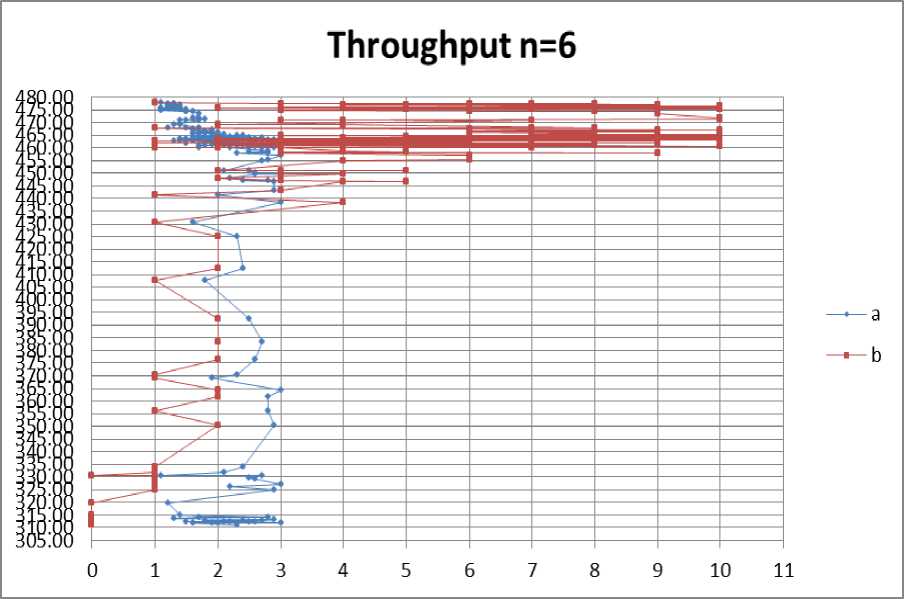
Fig. 9: Throughput for no. of nodes =6
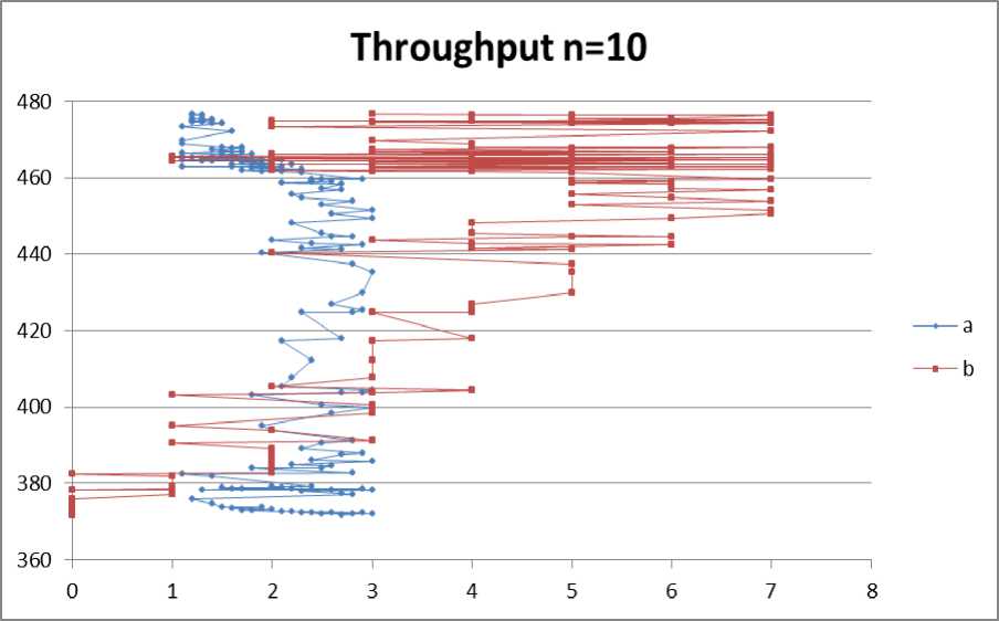
Fig. 10: Throughput for no. of nodes =10
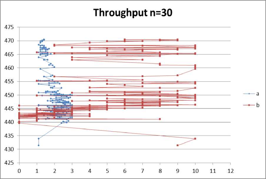
Fig. 11: Throughput for no. of nodes =30
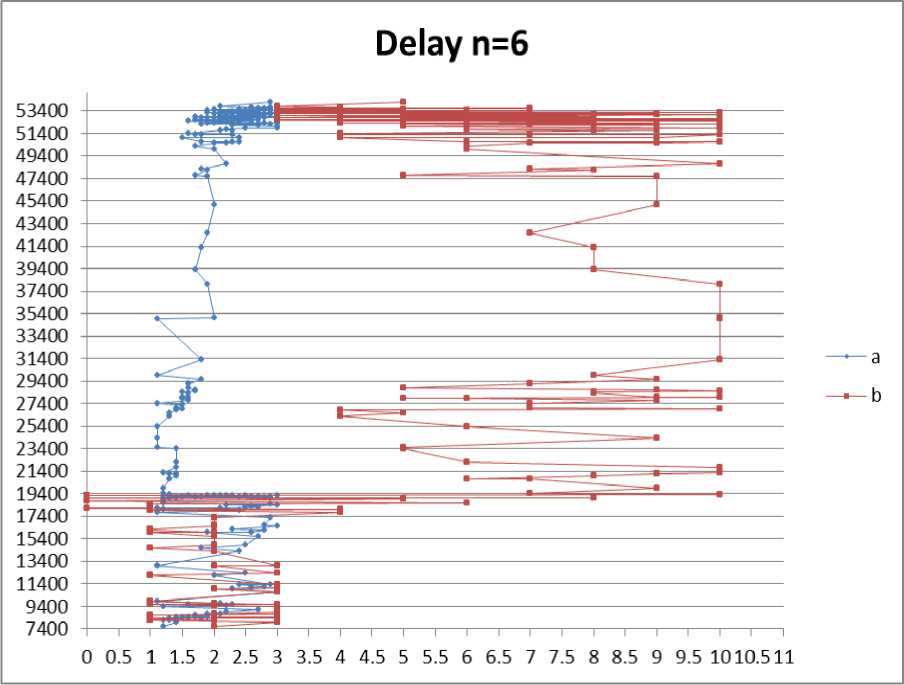
Fig. 12: End to end Delay for no. of nodes =6
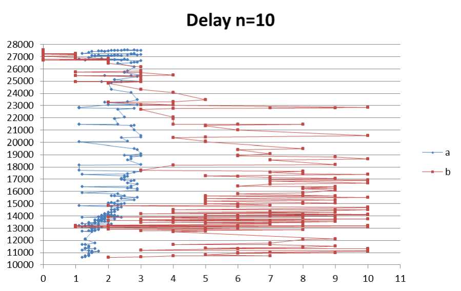
Fig. 13: End to end Delay for no. of nodes =10
Delay n=30
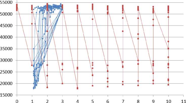
Fig. 14: End to end Delay for no. of nodes =30
According to the graphs shown and the tables in Appendix A we deduce that the optimum values of “a” and “b” are:
According to throughput measurement:
1 For n=6: a=1.1, b=1
According to delay measurement:
1 For n=6: a=1.2, b=2
2 For n=10: a=1.2, b=2
3 For n=30: a=1.1, b=4
2 For n=10: a=1.2, b=3
3 For n=30: a=1.4, b=6
The simulation result lead us to more than one optimum values of “a” and “b” according to circumstances the network based on.
-
[10] John G. Proakis, Massoud Salehi, “Digital communications”, McGraw Hill Higher Education, 2007
-
VII. Conclusion
This paper aims to minimize the delay time through wireless communication by changing the BEB algorithm. The Protocol CSMA / CA is a protocol that manages access to the radio channel by performing an arbitration based on time. This causes many problems in relation to time transmission between mobiles moving in a cell 802.11. what we have done show that the protocol using CSMA / CA access time believed rapidly when the number of stations and / or the network load increases or other circumstances affects the network.
Our objective is to minimize the time transmission cycle of the information between mobiles moving in a Wi-Fi. We reach our solution by changing two main functions in the BEB algorithm and our study proves that the changes we made give an acceptable result. We made the simulation according to variable number of nodes and for each one we get a new values of “a” and “b”. Future studies will be to create a fuzzy logic function to make choice of the optimum values of “a” and “b” according to specific rules and parameters.
References Modified Binary Exponential Backoff Algorithm to Minimize Mobiles Communication Time
- http://www.isi.edu/nsnam/ns/.
- Tutorial for the Network Simulator NS, http://www.isi.edu/nsnam/ns/tutorial/,2006.
- www.opnet.com.
- Gilberto flores Lucio, Marcos Paredes-Farrera, Emmanuel Jammeh, Martin Fleury,Martin J.Reed, Opnet Modeler and NS2: comparing the accuracy of network simulator for packet-level analysis using a network testbed, WSEAS Transactions on Computers, Issue 3,Volume 2:700-707 July 2003.
- P. Anelli, E. Horlait, « Ns-2: principle », version 1.3, 1999.
- Sabri Benfarhat, « rapport interne équipe réseau et protocole », LIMOS, Clermont Ferrand, 2007.
- Byung-Jae Kwak, Nah-Oak Song, Miller, “Performance analysis of exponential backoff”, Networking, IEEE/ACM Transactions on , volume 13, issue 2, april 2005.
- M. M. Carvalho, J. J. Garcia-Luna-Aceves, “Delay analysis of IEEE 802.11 in single-hop networks”, Proc. of IEEE ICNP, Nov. 2003.
- J. Chittamuru, A. Ramanathan, M. Sinha, “Simulation of Point Coordination Function for IEEE 802.11 Wireless LAN using Glomosim”, 2006.
- John G. Proakis, Massoud Salehi, “Digital communications”, McGraw Hill Higher Education, 2007.
