Motion Control of Five Bar Linkage Manipulator Using Conventional Controllers Under Uncertain Conditions

Author: Gopal Krishan, V. R. Singh
Journal: International Journal of Intelligent Systems and Applications(IJISA) @ijisa
Article in issue: 5 vol.8, 2016.
Free access
Robot trajectory tracking has been the core functioning unit in the modern industrial environment wherein the accuracy in the motion control of robotic manipulators is the main area of research. Based on the fact that the working of these automatic robotic machines is highly influenced by the disturbances, this paper constitutes various conventional controllers for the motion control of five bar linkage manipulator. To verify the performance of proposed conventional controllers, these are made to work with two different trajectories. Common disturbances like payload & friction has been incorporated in the five bar linkage manipulator system for validation purpose. Simulation results prove that the performance of SMC based controller is better when compared with other conventional controllers.
Motion Control, Robotic Manipulator, Trajectory Tracking, Sliding Mode Control, Computed Torque Control
Short address: https://sciup.org/15010821
IDR: 15010821
Text of the scientific article Motion Control of Five Bar Linkage Manipulator Using Conventional Controllers Under Uncertain Conditions
Published Online May 2016 in MECS
Most industrial robots are primarily, position controlled systems and this type of control mechanism is adequate for most industrial applications involving tasks that require high precision as in electronic assembly, medical robots for robot-assisted surgery, high speed tasks like visual serving. Applications involving high payload as in space craft maneuvers call for more precise and sophisticated control strategies.
A robot manipulator is a non-linear system comprising of mechanical linkages driven by electronic and electrical signals. The performance of these non-linear robotic systems can be enhanced by designing a non-linear controller. Generally, these non-linearities are neglected by linearizing the system around the operating point so as to use the ordinary linear controllers. But these controllers are of little use in case the system is having significant non-linearities in the robot dynamics [19]. Many researchers have done great work for the design of non-linear controller for robot manipulators [19-25].
Trajectory tracking is one of the most important applications of industrial robotic manipulators. Accuracy in tracking of a path by a manipulator can be achieved only if the dynamics of the system are perfectly known. Uncertainties in the mechanical manipulators such as payload changes, friction etc. affect its dynamics and hence its performance. Hence to get accurate mathematical model of a manipulator system is an impossible task. To compensate, specialized control schemes are required for specialized robotic manipulator like a five bar linkage manipulator.
In this paper dynamics of five bar linkage manipulator are given in section II. Section III deals with the details of conventional controllers. Section IV contains simulation and results obtained. Section V concludes the paper followed by references.
-
II. Fundamentals
In recent years, parallel manipulators have become popular among researchers and industrial applications as these manipulators can act as robot manipulators as well as machine tools [15]. There are multiple kinematic chains connecting a fixed base and a moving platform in parallel manipulators. Forces which are produced due to the result of actuated joints act in parallel in order to control the motion of the manipulator. This load is shared by different actuators in different chains. Hence, this class of manipulators have high stiffness and high load bearing capacity. Positioning accuracy of such manipulators is also high because the joint errors can be balanced considerably for a parallel design of manip
-
A. Dynamic Model of Five Bar Linkage manipulator
A five bar linkage manipulator is a special class of parallel manipulators where a minimum of two kinematic chains control the motion of end-effectors. Robotic research in this class of manipulators has seen active participation of researchers over the last twenty years [15]. The five bar linkage manipulator verifies the central strategies for all multi-link manipulators. (N-1) links of manipulator move in a vertical plane with the help of two prismatic or revolute motors. Elbow, spherical and cylindrical manipulators belong to this class of manipulators. The schematic diagram of five bar manipulator control is shown in Fig. 1.
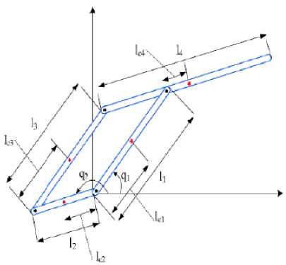
Fig.1. Schematic diagram of a five bar linkage parallel manipulator [1].
Two servomotors in this manipulator induce angular motion in link 1 and link 2 rotating about the revolute joints Q1 and Q2. In this two DOF mechanism, q3 and q4 are written as functions of q1 and q2. The dynamic model of the mechanism is derived from the reduced model method for closed chain mechanism. The dynamic model of the parallel manipulator is derived:
The system equations representing the dynamics of Five Bar Linkage are represented below [16] in (1)-(4).
∂М 12 ,
τ1=(M11+Ih)q̈ 1+M11 q̈ 2 q2 +g(m1lCl+m3lсЗ
∂ԛ
+m4l4)cos(q4)
∂М 12 -2 , ,
τ2 =(M22 +Ih)q̈ 2 +M12q̈ 1 q1 +g(m2lс2 +m3l2
∂ԛ
-m4lс4)cos(q2)
where,
M11=I11+I11 +m1lС1 +m3lСЗ +m4l1
M22 =I11+I11 +m2lс2 +m4l С4 +m3l2
M12 =M21=(m3lСЗ l2 -m4l с4 l1)cos(q1 -ԛ2)
where q 4 is the joint variable. τ4 and I h are torque and hub inertias respectively. I1,l1,lci and mi represent the inertia matrix, link length, distance of center of gravity and mass of the link respectively. Mis the inertia matrix of the entire manipulator. In all of the equations the index idisplays the i th motor.
-
B. Disturbances
Disturbances are the unwanted signals interfering with the model dynamics. Effect of most common existing uncertainties in the manipulator system naming, payload changes and friction are included in the present study.
-
i. Payload changes in mass of link 2:
m2 =m2o +Δm2 (5)
-
ii. Friction is one of the most common & dynamic uncertainty present in the robotic manipulator system. The classical model for friction incorporates coulomb and viscous friction models. The static model of friction considered in this paper is given below [17].
F = ̇+ Fcsgn ( ̇) (6)
where Fv is a diagonal matrix with diagonal elements as static friction constants and Fc is a diagonal matrix representing coulomb friction constants, ̇ is joint angle velocity for each link of the manipulator.
-
C. Trajectories to be Tracked
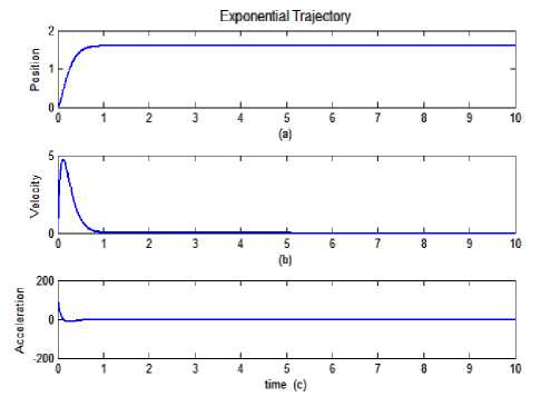
Fig.2. Exponential Desired Motion Trajectory.
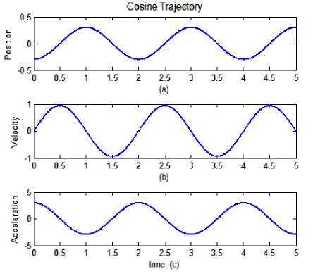
Fig.3. Cosine Desired Motion Trajectory.
-
III. Control Systems
This section contains the mathematical formulations and the brief overviews of the various conventional controllers of this paper for the motion control problem of robotic manipulator.
-
A. Proportional-Derivative(PD) Controller
Most of the industrial robot controllers are based on proportional-derivative (PD) or proportional-integral-derivative (PID) control techniques due to their simplicity of operation and satisfactory performance [13]. Moreover the robust performance of PID controllers allows the controlled plant work in wide operating range [4]. PD controller has some of its own issues. High control gains in PD controllers are generally selected to meet the desired tracking performance but it may cause vibration problems and noise amplification. To solve this some implementations in PD like gravity compensation has been given in literature [5].
The control term obtained for a PD controller is given as:
т = ( t )+ Kdt ̇( t )- F (7)
where, Kp and K d are suitable positive definite diagonal n x n matrices. Values of the controller constants i.e. Kp and K d are calculated by TAE (Trial And Error) method.
-
B. Computed Torque Controller(CTC)
Computationally complex Computed Torque Control (CTC) method of robot control is a model based control method which utilizes dynamics model of the system to compute the control signals that are given as input to the system. It also overcomes the problems faced in PID controllers. Its functioning is based on the mathematical model of the system dynamics to generate the control signal to compensate for the rigid body dynamics of the physical system. CTC controller performs effectively especially at higher speed and higher accelerations with massive payloads. This method of control can better tolerate the external disturbances such as payload changes if the dynamics of the payload are less significant compared to the dynamics of the system under control [6].
It is a model-based control method which utilizes the dynamics model of the system to compute the control torque signals. The control torque equation of the CTC is given as:
M(q̈d+k ė +kpe)+V(q̇d+k e+k ∫е)+G
- F =
where ∫е represents the integral error.
-
C. Sliding Mode Controller(SMC)
Sliding Mode Controller (SMC) is significantly nonlinear control scheme under conditions of partly uncertain dynamic parameters of the system [26]. SMC method of manipulator control is a special class of the variable-structure systems (VSSs) [7]. It has been widely used in practical applications due to its simplicity and robustness against parameter variations and disturbances [8]. SMC control theoretically achieves perfect tracking performance. Uncertainties in the system are well entertained by SMC manipulator control utilizing the non-linear feedback laws [8-10]. Robustness in tracking is assured in sliding mode controller as it can reject uncertainties and disturbances effectively. SMC has been applied to various areas of engineering due to its good tracking performance and robustness to external disturbances [11-14].
The conventional sliding mode control used sliding function definition involving the position error and the velocity error of the form (9)
σ(t) =ė +Ʌ! e (9)
In this paper, the sliding function is extended to include the integral error term. Therefore, the sliding function is defined as in (10)
σ(t) =ė +Ʌ!e+Ʌ2 ∫ е dt (10)
where Ʌ2_ and Ʌ2 are constant positive definite diagonal matrices
Torque equation for SMC is given as:
τ=-M( ∧ ! ė + ∧ 2е-q̈d)+V
(q̇ d - ∧ ! е-Λ2∫ е dt)+G-Ασ-Κ (11)
where A=[a2_,a2 …․an], ai is a positive constant, and
K= -k sgn (σ)
with
1, s > 0 sgn (о) ={0, s = 0
-1,s < 0
where k represents the discontinuous constant gain and produces unavoidable, non-required chattering in the system. Hence, it needs to be rectified.
-
IV. Experimental Evaluation And Result Discussion
Effectiveness of various controllers discussed in this paper is verified by simulating it on a 2-dof five bar linkage parallel manipulator. The manipulator is made to track two different types of trajectories in exponential and cosine. Uncertainties incorporated in the system are payload changes and friction. Numeric values of the parameters of the manipulator dynamics chosen are listed in Table 1.
Table 1. Parameters of the parallel manipulator [18]
|
S .No. |
Mass mt (kg ) |
Link 11 ( m ) |
Mass Centre m, (m) |
Inertia к ( 10“2 kgfm2 ) |
|
1 |
0.91 |
0.080 |
0.006 |
0.847 |
|
2 |
0.28 |
0.100 |
0.028 |
0.630 |
|
3 |
0.38 |
0.250 |
0.125 |
4.002 |
|
4 |
0.38 |
0.250 |
0.125 |
4.002 |
|
5 |
- |
0.250 |
- |
- |
These performance indices chosen for evaluation comparison of manipulator are the maximum value of tracking error, minimum value of the tracking error, average of the tracking error for both the joints. Various performance indices have been tabulated in different tables for the manipulator working under perfect and imperfect conditions. Table 2 gives the numeric indices for exponential trajectory under perfect conditions. Performance indices for exponential trajectory under imperfect conditions have been given in Table 3.
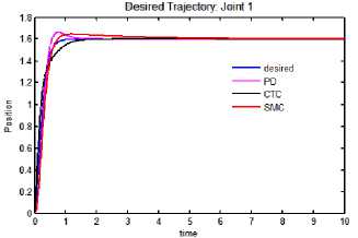
a. Tracking performance: joint 1
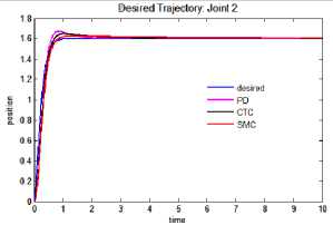
b. Tracking performance: joint 2
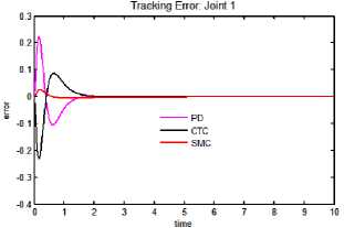
c. Tracking error: joint 1
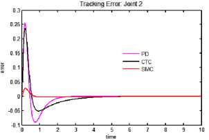
d. Tracking error: joint 2
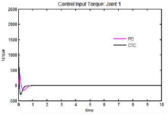
e. Control input torque: joint 1
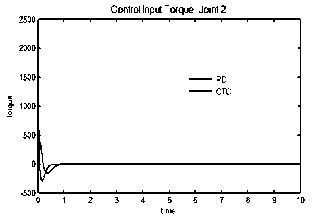
f. Control input torque: joint 2
Fig.4. Tracking performance, tracking error and control input torque for exponential trajectory.
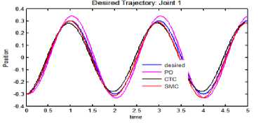
(a) Tracking performance: joint 1.
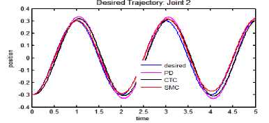
(b) Tracking performance: joint 2.
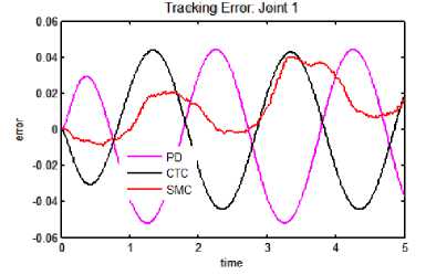
(c) Tracking error: joint 1
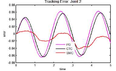
(d) Tracking error: joint 2.
torque
Control Input Torque: Joint 1
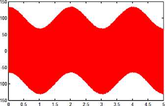
(e) Control Input Torque: joint 1
Fig.5. Tracking performance, error and control torque for cosine trajectory.
Control Input Torque: Joint 2
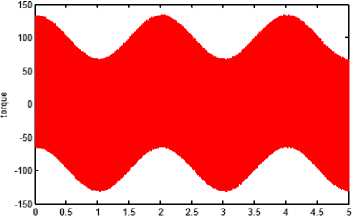
(f) Control Input Torque: joint 2.
Table 2. Performance indices under perfect conditions: exponential trajectory
|
Controller |
Joint-1 |
Joint-2 |
||||
|
Max. of tracking error (e max ) |
Min. of tracking error (e min ) |
2-norm of tracking error |
Max. of tracking error (e max ) |
Min. of tracking error (e min ) |
2-norm of tracking error |
|
|
PD |
0.2247 |
0.0051 |
1.1036 |
0.2558 |
0.0868 |
1.2992 |
|
CTC |
0.0855 |
0.2310 |
1.1200 |
0.2384 |
0.0476 |
1.2236 |
|
SMC |
0.0264 |
0.0030 |
0.1363 |
0.0284 |
0.0019 |
0.1481 |
Table 3. Performance indices under imperfect conditions: exponential trajectory
|
Controller |
Joint-1 |
Joint-2 |
||||
|
Max. of tracking error (e max ) |
Min. of tracking error (e min ) |
2-norm of tracking error |
Max. of tracking error (e max ) |
Min. of tracking error (e min ) |
2-norm of tracking error |
|
|
PD |
0.2226 |
0.1044 |
1.1191 |
0.2550 |
0.0902 |
1.3042 |
|
CTC |
0.0872 |
0.2351 |
1.1262 |
0.2378 |
0.0514 |
1.2292 |
|
SMC |
0.0261 |
0.0047 |
0.1408 |
0.0283 |
0.0025 |
0.1490 |
Table 4. Performance indices under perfect conditions: cosine trajectory
|
Controller |
Joint-1 |
Joint-2 |
||||
|
Max. of tracking error (e max ) |
Min. of tracking error (e min ) |
2-norm |
Max. of tracking error (e max ) |
Min. of tracking error (e min ) |
2-norm of tracking error |
|
|
PD |
0.0437 |
0.0514 |
0.7091 |
0.0621 |
0.0645 |
0.9329 |
|
CTC |
0.0436 |
0.0441 |
0.6490 |
0.0579 |
0.0631 |
0.8937 |
|
SMC |
0.0415 |
0.0097 |
0.4785 |
0.0091 |
0.0410 |
0.4801 |
Table 5. Performance indices under imperfect condition: cosine trajectory
|
Controller |
Joint-1 |
Joint-2 |
||||
|
Max. of tracking error (e max ) |
Min. of tracking error (e min ) |
2-norm |
Max. of tracking error (e max ) |
Min. of tracking error (e min ) |
2-norm of tracking error |
|
|
PD |
0.4420 |
0.0519 |
0.7161 |
0.0624 |
0.0648 |
0.9355 |
|
CTC |
0.0439 |
0.0444 |
0.6523 |
0.0581 |
0.0637 |
0.8966 |
|
SMC |
0.0403 |
0.0090 |
0.4120 |
0.0080 |
0.0417 |
0.4155 |
-
V. Conclusions
References Motion Control of Five Bar Linkage Manipulator Using Conventional Controllers Under Uncertain Conditions
- Astrom K.J. and Hagglund T., PID Controllers: Theory design and tuning. Instrument Society of America: Research Triangle Park, N.C. 1995.
- Dwyer A. O., Handbook of PI and PID Controller Tuning Rules. London, Britain: Imperial College Press, 2003.
- Choi, Chung and Suh, Performance and H∞ optimality of PID trajectory tracking control for lagrangian system. IEEE Transactions on Robotics and Automation. 16(7), December 2001.
- Goel A., Uniyal A., Bahuguna A., R. Patwal S., and Ahmed H., Performance Comparison of PID and Fuzzy Logic Controller using Different Defuzzification Techniques for Positioning Control of DC Motors. Journal of Information Systems and Communication. 3(1) : 235-238, 2012. Kelly R., PD control with desired gravity compensation of robotic manipulators: a review. International Journal of Robotic Systems. 16(5) : 660-672, 1997.
- Chen Q., Chen H., Wang Y. and Woo P., Global stability analysis for some trajectory-tracking control schemes of robotic manipulators. Journal of Field Robotics. 18(2) : 69-75, 2001.
- http://tspace.library.utoronto.ca/bitstream/1807/11687/1/MQ28868.pdf
- Utkin V. I., Variable structure systems with sliding modes. IEEE Trans. Autom. Control. AC-22(2) : 212-222, 1977.
- Utkin V. I., Sliding Mode in Control and Optimization. New York: Springer-Verlag, 1992.
- Hung J. Y., Gao W., and Hung J. C., Variable structure control: a Survey. IEEE Trans. Ind. Electr. vol. 40 : 2-22, 1993.
- Young K. D., Utkin V. I., and Özgüner Ü., A control engineer's guide to sliding mode control. IEEE Trans. Control Sys. Tech. vol. 7 : 328-342, 1999.
- Abidi K. and Šabanovic A., Sliding-Mode Control for High- Precision Motion of a Piezostage, IEEE Transactions on Industrial Electronics. 54(1) : 629-637, 2007.
- Bristow D. A. and Alleyne A. G., A High Precision Motion Control System With Application to Microscale Robotic Deposition. IEEE Transactions on Control Systems Technology. 14(6) : 1008-1020, 2006.
- Ghorbel F., Chételat O. and Longchamp R., A Reduced Model for Constrained Rigid Bodies with Application to Parallel Robots. In Proc. of the IFAC Symposium on Robot Control SYROCO'94, Capri, 1994.
- Bartolini G., Pisano A. and Usai E., Digital Second-Order Sliding Mode Control for Uncertain Nonlinear Systems. Automatica. 37(9) : 1371-1377, 2001.
- Merlet J. P., Parallel robots. 2nd ed. Dordrecht, the Netherlands: Springer, 2006.
- Eshaghi S., Kharrati H., Badamchizadeh M.A. and Hasanzadeh I., A predictive controller based on dynamic matrix control for a nonminimum phase robot manipulator. International Journal of Control, Automation and Systems. 10(3) : 574-581, 2012.
- Armstrong-Helouvry B., Dupont P. and Canudas C., A Survey of Models, analysis tool and compensation methods for the control of machines with friction. Automatica. 30(7) : 1083-1138, 1994.
- Acob J. M., Pano V. and Ouyang P. R., Hybrid PD Sliding Mode Control of a Two Degree of- Freedom Parallel Robotic Manipulator. In Proc. of the 10th IEEE International Conference on Control and Automation (ICCA), China, 2013.
- Kankashwar M.R. and Kharrati H., Design of Multivariable Controller Based on Feedback Linearization for Five-Bar Linkage Manipulator. In Proc. of the 23rd Iranian Conference on Electrical Engineering (ICEE), Iran, 2015.
- Hassanjadeh I., Kharrati H. and Bonab J.R., Model Following Adaptive Control for a Robot with Flexible Joints. In Proc. of Canadian Conference on Electrical & Computer Engineering (CCECE), Canada, 2008.
- Hassanjadeh I., Mobayen S. and Kharrati H., Design of MIMO Controller for a Manipulator using Tabu Search Algorithm. In Proc. of International Conference on Intelligent and Advanced Systems (ICIAS), 2007.
- Kwok D.P. and Sheng F., Genetic Algorithm and Simulated Annealing for Optimal Robot Arm PID Control. In Proc. of IEEE World Congress on Computational Intelligence, 1994.
- Rodger S., Fossen T.I. and Kokotovic P.V., Robust Output Maneuvering for a Class of Non-Linear Systems. Automatica 40(3) : 373-383, 2004.
- Eshaghi S., Kharrati H., Badamchizadeh M.A. and Hasanzdeh I., A Predictive Controller Based on Dynamic Matrix Control for a Non-Minimum Phase Robot Manipulator, International Journal of Control, Automation & Systems, 10(3) : 574-581, 2012.
- Ouyang P.R., et.al., Revisiting Hybrid Five Bar Mechanism : Position Domain Control Application. In Proc. of IEEE International Conference on Information & Automation (ICIA), 2014.
- Nazari I., Hosainpour A., Piltan F., Emamzadeh S. and Mirzaie M., Design Sliding Mode Controller with Parallel Fuzzy Inference System Compensator to Control of Robot Manipulator. International Journal of Intelligent Systems and Applications, vol. 04 : 63-75, 2014.
