NoC Research and Practice: Design and Implementation of 2×4 2D-Torus Topology

Автор: Xingang Ju, Liang Yang
Журнал: International Journal of Information Technology and Computer Science(IJITCS) @ijitcs
Статья в выпуске: 4 Vol. 3, 2011 года.
Бесплатный доступ
Design and Implementation of network on chip interconnection architecture for eight compute-intensive processors are mainly presented in this paper. Firstly, it introduces the basic concept and architecture of the NoC, through analysis and comparison of three common NoC topologies, 2×4 2D Turos is chosen as the final topology, and the single routing node architecture is designed, including packet format, routing and arbitration. Secondly, routing nodes coding, routing algorithm and node degree routing direction are designed. Thirdly, the programming and simulation of 2×4 NoC interconnection architecture are designed, and it achieves uninterrupted operation. The result shows the correctness of the interconnection architecture design. Finally, it chooses XC4VSX55-12ff1148 of vertext 4 to synthesize, the maximum frequency can up to 268 MHz, which provides foundation of subsequent research and application.
Network on Chip, On-chip communication, topology, routing node, routing algorithm, uninterrupted operation
Короткий адрес: https://sciup.org/15011635
IDR: 15011635
Текст научной статьи NoC Research and Practice: Design and Implementation of 2×4 2D-Torus Topology
Published Online August 2011 in MECS
Nowadays, as the number of processors on a single chip and the computing complexity increasing, the interconnection and communication mechanism among the processors become important factors affecting the performance of chip-multiprocessor. It needs more effective communication and interconnection among the processors to improve performance, rather than relies on their processing speed. It needs full consideration of communication demands and characteristics of all kinds of processors, and should provide better data transmission performance in limited conditions. Such as chip area, power consumption, data bandwidth and so on. Therefore, it requires higher demands for on-chip communication, such as high speed, high throughput, high bandwidth, while small area and low power consumption. Traditional interconnection architecture of the chip-multiprocessor, such as on-chip bus, crossbar, and so on, can’t satisfy these requirements because of the problems of reusability, flexibility and scalability. It needs a more perfect and effective interconnection technology.
NoC has been a research hot spot because of its mass data processing, multitasking parallel computing, scalability and flexibility and so on [1]. It uses routing and packet switching technology, adapts the message communication model, and connects resources to network communication. This reduces chip area and power consumption, and improves system performance, reliability, reusability and scalability. It adapts the communication requirement for “high data throughout and low communication delay” in chip-multiprocessor. At the same time, the communications among the processors depend on routing nodes with short link, which can effectively resolve interconnection delay. NoC uses for layered idea of communication protocol, which provides feasibility to overall control power consumption from physical level to system level. NoC architecture has a trend to replace on-chip bus architecture, and appears as a better effective architecture for on-chip communication in large scale complex chip-multiprocessor in future [2].
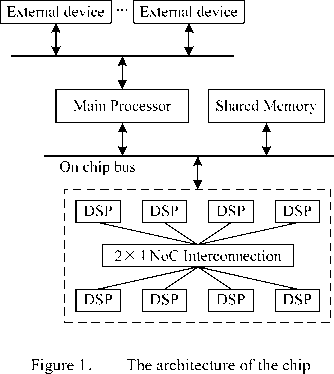
2×4 NoC interconnection architecture is mainly used as shown in figure 1. It is a heterogeneous structure; main processor as a control-intensive processor for system management and controlling, while eight DSPs as compute-intensive processors for mass data processing. It uses on-chip bus and NoC interconnection architecture, on-chip bus connects main processor, shared Memory and external devices, while eight DSPs interconnect each other with NoC interconnection architecture, which communicates with main processor through on chip bus.
There are several important choices to consider in NoC design, such as topology, routing strategy and switch strategy and so on. In this paper, it introduces the basic concept and architecture of NoC, through analysis and comparison of 2×4 NoC topologies, 2D Turos is chosen as the final topology. By package design, coding design, routing and arbitration design and routing algorithm design, the programming and simulation of 2×4 NoC interconnection architecture are implemented, and it achieves uninterrupted operation. XC4VSX55-12ff1148 of vertext 4 is chosen to synthesize and implementation, the maximum frequency can up to 268MHz, which provides foundation of subsequent research and application.
-
II. NoC Overview
NoC research began in 1999, its main idea is transplanting the network technology to chip design which solves communication bottleneck problem and global clock problem. In NoC architecture, computing resources, memory resources and I/O resources are interconnected by exchange switches and realized in a single chip. Its basic communication is packet switching which uses Globally Asynchronous Locally Synchronous systems (GALS) communication mechanism: each resource node can works on its own clock domain, and it communicates asynchronously between different resources nodes through communication nodes which solves one-clock synchronous problem. It separates computation from communication: resource node executes computing tasks, and then transmits data to network; communication node is responsible to data transition, it sends data from source node to destination node along with a determined direction.
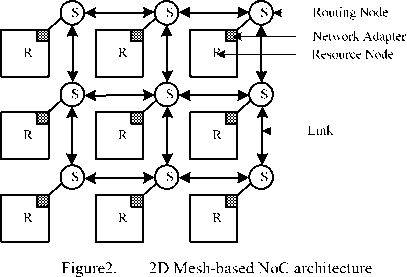
NoC basic architecture includes resource node, communication node, topology and links, Figure 2 shows a 3×3 mesh-based NoC architecture [3]. Data is sent from resource node to input channel of the communication node through network adapter, and then transmitted to corresponding output channel through crossbar in communication node, finally sent to the next communication node by links or to the destination node through network adapter.
-
• Resource node: (or computing node) is the node to execute computing tasks; it can be CPU, SoC, all kinds of IPs with special functions, memory arrays or reconfigurable hardware and so on.
-
• Communication node: deals with data communication among resource nodes; it includes routing node and network adapter, which transmits data from its input port to one or more output port.
-
• Routing node: determines data flow. It first receives data in input port, and then sends data from corresponding output port through certain routing and arbitration.
-
• Network adapter (or NI: Network Interface): implements the interface by which cores connect to the NoC. Its function is to decouple computation from communication.
-
• Topology: reflects the links and distribution of routing node, distribution and interconnection between routing node and link in chip. Figure 2 shows a 3×3 2D mesh topology.
-
• Link: connects each communication node and provides communication bandwidth. It consists of one or more logic or physical channels.
-
III. Ananysis and Comparison of NoC
Topologies
There are three typical topologies in 2×4 NoC, 2D Mesh, 2D Torus and hierarchical Mesh.
Figure 3 is 2×4 2D Mesh topology. R0~R7 are eight routing nodes, one routing node connect adjacent nodes through link, and each routing node connect each DSP through NI. R1, R2, R5, R6 are three node degrees, and R0, R3, R4, R7 for two node degrees.
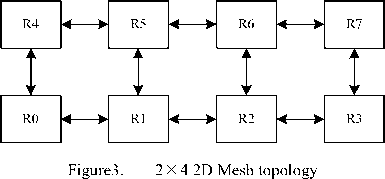
Figure 4 is 2×4 2D Torus topology. It adds long links in boundary nodes comparing with 2D Mesh, R0 and R3, R4 and R7 connects each other by long links. Each routing node is three node degrees.
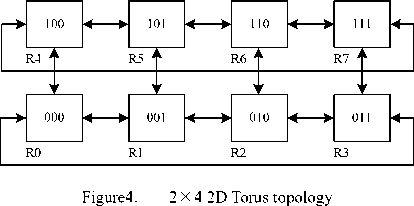
Figure 5 is 2×4 hierarchical Mesh topology. It connects between routing nodes for 2 hops with long links. R1, R2, R5 and R6 are four node degrees, and R0, R3, R4, R7 for three node degrees.
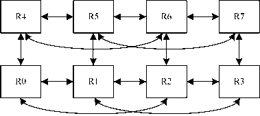
Figure5. 2 X 4 hierarchical Mesh topology
The ability of data transmission relies mainly on topology in NoC. It restricts the whole network information transmission speed, and has a crucial influence to network delay, throughput, area, power consumption, and further influences network routing strategies and mapping algorithm and so on. The topology should be simple, regular, easily realizable, good reusability and scalability because of the influence of communication needs, physical space, layout wiring and encapsulation, chip area and power consumption and so on [4]. Therefore, the choice of appropriate topology is one of the key issues in NoC design. Table 1 shows the comparison of attributes of three NoC topologies.
TABLE 1 .
COMPARISON OF ATTRIBUTES OF THREE TOPOLOGIES
|
Topology (2×4) |
Network diameter |
Node degree |
Number of links |
|
2D Mesh |
4 |
2,3 |
10 |
|
2D Torus |
3 |
3 |
12 |
|
hierarchical Mesh |
3 |
3,4 |
14 |
The advantages of 2D Mesh topology are that node connection and routing algorithm are simple, no longer links, easy to physical implementation [5]. But the network diameter is quite large (4), it can’t provide high enough bandwidth, node degree is not completely asymmetrical, which influences the design of routing node, and the scalability is also poor.
2D Torus topology is regular; each routing node is three node degrees, so the scalability is good. Its ideal throughput more than 2D Mesh topology [6], network diameter (3) is small, so it is easy to design routing node. There are only two long links, which is less influence to physical realization.
In hierarchical Mesh topology, network diameter (3) is small, and it can provide high bandwidth. But there are many circuits, node degree is asymmetrical, routing algorithm and arbitration is more complex than the former two topologies, and scalability is also poor.
Through above analysis and comparison, 2D Torus topology is regular, simple, small network diameter, good scalability and easily to physical realization, which is chosen as the final topology. As Figure 5 shows, DSP0~DSP7 are DSP processors which link with their respective NI, R0~R7 are eight routing nodes. Where, R0~R3 is not links directly with on-chip bus, and they communicate with on-chip bus through R4~R7 which can directly communicate with on-chip bus.
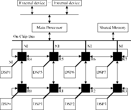
Figure 5 interconnection architecture of 2×4 multi-core processor
-
IV. The Design of Routing Node
-
A. Routing node architecture
In 2D Torus topology, each routing node is three node degrees, adding a port which connects its DSP through NI, the routing node architecture has 4 input ports and 4 output ports. Therefore, the basic routing node architecture is shown in figure 6 [7]. It consists of input/output channel, buffer, switch, routing and arbitration and link controller and so on.
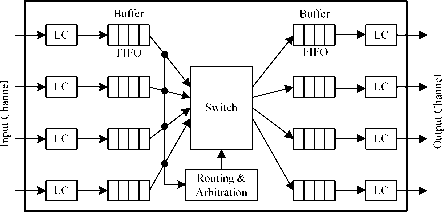
Figure 6 the basic routing node architecture
-
• Input channel: it injects data from resource node through NI or output port of other routing node into its routing nodes.
-
• Link controller (or LC): provides handshaking signal between adjacent routers and achieves information transmission on physical channel.
-
• Buffer: uses to storage temporarily data, it is usually composed of FIFO. In figure 6, each input channel and output channel consists of FIFO memory.
-
• Switch: connects input buffer and output buffer. High speed router usually adapts whole connection crossbar.
-
• Routing and arbitration: implements routing algorithm and controls switch on/off. The element allows arbitration if multiple messages ask for a same output channel at the same time.
-
• Output channel: it ejects data from its routing
nodes into corresponding resource nodes through NI or other routing node.
Routing node is the bridge connection among network nodes; it is a key component in NoC. In order to improve the ability of data parallel transmission, it adapt the input/output buffer architecture in this paper, as figure 6 shows, each input channel and each output channel consists of FIFO memory.
-
B. Packet format
Wormhole switching strategy is a popular switching strategy at present [8]; each packet is divided into some fixed length flits, and each packet head includes routing and controlling information. All flits forward transmit along the routing path, until reach destination node. However, the following flits will be stayed in corresponding routing node and blocked the pathway while packet head is blocked, so the package may simultaneously occupy more intermediate routing nodes.
In this paper, the switching strategy is referenced in [9]; the difference with wormhole switching strategy is that each flit contains data, routing information and other information. So, there are no packet head and packet tail, and no complex data transmission control protocol. The routing node only detects routing information of each flit, and the data can be transmitted to corresponding destination node, table 2 shows the flit format.
TABLE 2 .
FLIT FORMAT
|
Controlling information |
Routing information |
Data |
Where, controlling information contains, for example, flag is determined data available or not, flit serial number is the serial number of flit, and so on; routing information is the destination node information, such as coordinate or address.
-
C. Routing and arbitration
The design of routing node in this paper is a point to point data transmission, each input port has a chance to transmit data to four output ports, it will send requirement to routing and arbitration while data analysis, it reflects data should be transmitted to which output port, figure 7 shows sending requirement format.
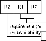
Output port
1: Data available
0: Data inavailable
Figure 7 sending requirement formats
Each input port has sending requirement signal which is obtained by routing algorithm, for example:
-
• Req(0)=“100”, means input 0 sends
requirement to output 0;
-
• Req(1)=“101”, means input 1 sends
requirement to output 1;
-
• Req(2)=“110”, means input 2 sends
requirement to output 2;
-
• Req(3)=“111”, means input 3 sends
requirement to output 3;
The competition among input ports appears when several input ports simultaneously send requirements to the same output port. Round robin (RR) algorithm is used widely in NoC because of its simplicity and practicability [10], so it is used in this paper. Which input port is served relies on the output port which input port is served for the last time; figure 8 shows the RR algorithm.
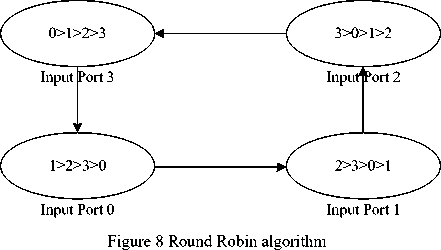
Where “Input Port 0” means input port 0 is served for the last time. ‘0’,’1’,’2’,’3’ means current input port. For example, input port 0 is served for the last time; input port 1 is served firstly refer to RR algorithm when input port 0 and input port 1 simultaneously send requirements to same output port.
-
V . Design of 2 X 4 NoC Interconnection
Architecture
The routing node coding is shown in figure 3. When the destination coding and current coding of the absolute value of the highest level in the same column is 1, data is transmitted to Y direction, when is 0, data is transmitted to X direction; when the destination coding and current coding of the absolute value of the difference of low 2 is 0, data is returned to local direction; when is 1 or 2, data is transmitted to X direction along short link; when is 3, data is transmitted to X direction along long link. Suppose that the current coding is ( x 0 y 0 z 0 ), destination coding is ( x 1 y 1 z 1 ), marks a = |x 0 -x 1 |, b = |decimalizing ( y 0 z 0 ) - decimalizing ( y 1 z 1 )|, this description can be expressed as follows algorithm:
If a=1 then
Data is transmitted to Y+(or Y-) direction;
Else if a=0 then
If b=0 then
Data is transmitted to local direction;
Else if b=1 or b=2 then
Data is transmitted to X+(or X-) direction;
Else if b=3 then
Data is transmitted to X+3(or X-3) direction;
End if;
End if;
Due to the limited power consumption and area, routing algorithm not only sends data correctly to destination node, but also as simple as possible and efficient., data can be sent to destination node through the shortest routing direction and waiting time, Consequently, it can reduce transmission delay and improve throughput. Deterministic routing algorithm is widely used in many topologies because of the least consumed resources [11], in this paper, the routing algorithm is transmitted first to Y direction and then to X direction, it describes as shown above. It is the shortest distance deterministic routing algorithm Data is analyzed and determined the routing direction through comparison of the destination coding and current coding. Each routing node is 4 input ports and 4 output ports: local, x+ (or x-), Y+ (or Y-) and x+3 (or x-3). The definition of routing direction of routing node is shows in figure 9.

X- ( or X+3)

Figure 9 the definition of routing direction of routing node
Input definition:
-
• Input 0: local: external data inputs through NI;
-
• Input 1: X+ (or x-3): data from X+ direction or x-3 direction;
-
• Input 2: Y: data from Y direction;
-
• Input 3: X-(or X+3): data from X- direction or X+3 direction.
Output definition:
-
• Output 0: local: network data outputs through NI;
-
• Output1: X-(or X+3): data is transmitted to
-
X- direction along short link or to X+3 direction along long link;
-
• Output2: Y: data is transmitted to Y direction along short link;
-
• Output3: X+ (or X-3): data is transmitted to X+ direction along short link or to X-3 direction along long link.
According to the definition of routing node coding and topology in figure 3, and the definition of routing direction of routing node in figure 9, therefore, the design of 2x4 2D Torus topology is implemented.
-
VI. Implementation and Simulation
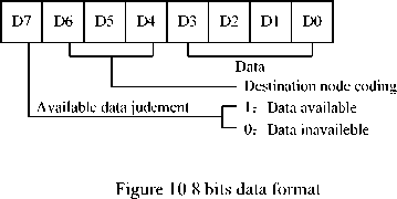
The design of 2×4 NoC interconnection architecture is designed by using Active-HDL software programming. Where interface protocol adopts request/response (or “req/ack”) handshaking protocols, buffer uses 64x8 bits FIFO. 8 bits data format is shows in figure 10. Each routing node contains current routing information; data is transmitted to corresponding routing direction by routing algorithm.
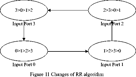
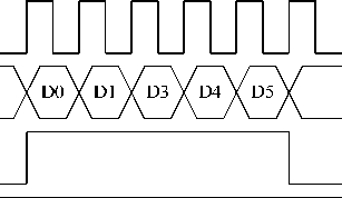
Because data transmission in single routing node is influenced by input and output buffering structure, routing and arbitration, data is transmitted to the final output needs several clock cycles. In order to improve network throughput and frequency, the data which is operated must be uninterrupted. In this paper, RR algorithm makes some changes, as figure 11 shows, for example, data of input port 0 is firstly transmitted if input port 0 is served for the last time, and input data X”00” as the flag of data end.
At the same time, the “req/ack” protocols makes some changes too, the initial value of “ack” is set as high in input channel and output channel. As figure 11 and figure 12 shown.
Clock input_data inputreq
inputack
Figure 11 Input “req/ack” timing diagram
In fugure 11, Clock is the clock signal; input_data is the data from input channel in routing node; input_req/input_ack is the “req/ack” protocol, the initial value of input_ack is set as high until the “full” signal from input FIFO is high; wr is the write signal. It can be see that data can be uninterruptedly written.
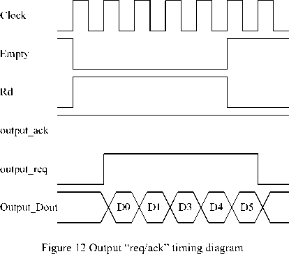
In figure 12, Clock is the clock signal; Empty is the “empty” symbol from output FIFO; Rd is the read signal; output_req and output_ack is the “req/ack” protocol, the initial value of output_ack is set as high until “busy” signal from NI is high; output_Dout is the data ejected into other routing node or resource node through NI. It can be see that data can be uninterruptedly read.
From above changes, data can achieve uninterrupted operation in routing node, which greatly improves data transmission throughput. In simulation environment, R0 routing node, for example, sends two data to R0~R7 respectively, according to the definition of 8 bits data format in figure 9, the input data is as follow:
R0 :
R2 :
R4 :
R6 :
”81” 、
”A1” 、 ”C1” 、
”E1” 、
”82” 、
”A2” 、 ”C2” 、
”E2” 、
00” ; ”00” ; ”00” ; ”00” ;
R1
R3
R5
R7
”91
B1
D1
F1
、
、
、
、
92” 、
B2” 、
D2” 、
F2” 、
”00” ;
”00” ;
”00” ;
”00” ;
The simulation result is shown in figure 13.
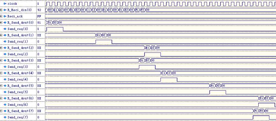
Figure 13 The simulation of 2×4 interconnection architecture
Where, R_Reci_din(0) is the local input port of R0, R_Send_dout(0)~R_Send_dout(7) are the eight local output port of routing node respectively; Send_req and Reci_ack are request/response signals, and the initial value of Reci_ack is set as high. According to the simulation result, input data is correctly sent to corresponding output port, and it achieves uninterrupted operation.
Finally, 2×4 2D Torus topology is implemented by FPGA device and is synthesized with ISE tool. FPGA device chooses xc4vsx55-12ff1148 of Vertex4. Table 3 shows the occupying resource of 2D Torus topologies
TABLE 3 .
OCCUPYING RESOURCE OF 2D TORUS TOPOLOGY
|
xc4vsx55-12ff1148 |
2D Torus |
||
|
Available |
Used |
Utilization |
|
|
Numbers of Slices |
24576 |
6735 |
27% |
|
Number of Slice Flip Flops |
49152 |
1664 |
3% |
|
Number of 4 input LUTs |
49152 |
9303 |
18% |
|
Number of bonded IOBs |
640 |
162 |
25% |
|
Number of G CLKs |
32 |
1 |
3% |
|
Max Frequency |
268.118MHz |
||
From above table, the maximum frequency can up to 268MHz. If it uses higher performance devices, such as Vertex5 or Vertex6, the frequency will get more improvement.
-
VII. Conclusion
It focuses on eight DSPs interconnection architecture design in a chip structure in this paper. Firstly, introduction of the basic concept and architecture of NoC, and then choice of topology and design of single routing node architecture are presented, including packet format, routing and arbitration; then 2x4 interconnection architecture is designed, including routing node coding, routing algorithm and node degree routing direction. Finally, it is designed by using Active-HDL software programming and simulation. In order to improve the efficiency of data transmission; the data can achieve uninterrupted operation. The maximum frequency can up to 268 MHz after synthesis, which provides reference to subsequent research. The next research focuses on performance analysis and evaluation of the architecture and NI design.
Список литературы NoC Research and Practice: Design and Implementation of 2×4 2D-Torus Topology
- Goossens K. A Ethereal Network on Chip: Concepts, Architectures and Implementations[J]. IEEE Design & Test of Computers, 2005, 22(5).
- Vivek Kumar Sehgal, Durg Singh Chauhan. State Observer Controller Design for Packets Flow Control in Networks-on-Chip. IBM Journal of Supercomputer, 2009.
- Tobias Bjerregaard and Shankar Mahadevan. A Survey of Research and Practices of Network-on-Chip. ACM Computing Surveys, 2006, 38: 1-51.
- Shuai Ding, Nin Wu, et al. The Research on System Level Modeling of Router for Network on Chip[J]. Microelectronics & Computer, 2009,26(1): 45-51.
- Yan Pan, Prabhat Kumar, John Kim, et al. Firefly: Illuminating Future Network-on-Chip with Nanophotonics. ISCA’09, 2009: 429-440.
- M. Mirza, S. Koohi, S. Hessabi,et al. An Empirical Investigation of Mesh and Torus NoC Topologies under Different Routing Algorithms and Traffic Models[C].the 10th Euromicro Conference on Digital System Design Architectures, Methods and Tools 2007:19-26.
- Duato, J., Yalamanchili, S., and Ni, L. Interconnection Networks: An Engineering Approach. Morgan Kaufmann. 2003.
- L. M. Ni and P. R. Mckinley. Wormhole Routing Techniques for Directly Connected Multicomputer Systems. ACM Computer Surveys, 1998, 26(5): 12-23.
- Chang Wu. The Research of Architecture and Key Communication Technology in Network on Chip [D]. xi’an: XiDian university, 2005.
- P P Pande, C Grecu, M Jones, et al. Performance Evaluation and Design Trade-offs for Network-on-Chip Interconnect Architectures. IEEE Transactions on Computers. August, 2005, 54(8): 1025-1040.
- E Bolotin, I Cidon, R Ginosar, et al. QNoC: QoS Architecture and Design Process for Network on Chip. J. Syst. Architecture: Euromicro J.Feb 2004, 50: 105-128.
