Numerical Analysis of Slot Position of Rectangular U Slot Microstrip Patch Antenna

Author: Harleen Kaur, Balwinder Singh Dhaliwal
Journal: International Journal of Wireless and Microwave Technologies(IJWMT) @ijwmt
Article in issue: 3 Vol.6, 2016.
Free access
The main focus of this paper is to study and analyze how the performance of rectangular U slot antenna is affected by the variation of U slot position. The work presented herein is a simulation based study. Experimentally, it has been revealed that variations in parameters such as the width and length of the U-slot, height and size of the patch, probe size and location as well as substrate permittivity can dramatically change the antenna's behavior. Till date, no analytical methods have been developed that accurately relate the complex relationships between the antenna dimensions and individuality. This paper describes the behavior of antenna with change of U slot position. A numerical solution is obtained by varying the various positions of U slot along all the axis and the effect of U slot position on various antenna output parameters is analyzed.
Microstrip Patch Antenna, Return Loss, Gain, Bandwidth
Short address: https://sciup.org/15012935
IDR: 15012935
Text of the scientific article Numerical Analysis of Slot Position of Rectangular U Slot Microstrip Patch Antenna
Published Online May 2016 in MECS
Available online at
The various slot shapes are available to fulfill the requirement of improvement in bandwidth. The etching of U slot on the Microstrip patch is considered to be a simple design [7] .Such a design does not make use of stacked or coplanar parasitic patches because either of these increases the thickness or the lateral size of the antenna. So, while changing the current distribution on the Microstrip patch enhancing the impedance bandwidth with sometimes more than one resonant frequency are obtained [8]. The loading of slot on the radiating patch results in increase of the current length that results in lowering fundamental resonance frequency which corresponds to reduced antenna size when compared to conventional patch antenna for a given resonant frequency.
-
2. Related Work
-
3. Variation of Positions of U Slot of the Patch
The earlier analysis and the empirical technique of U slot antenna are based on dimensional invariance relationships observed in the U-slot geometry and empirical design equations [9]. The strength of this method is that it converges on the optimized design quickly – if the desired frequency lies in the range in which the design equations are reliable. The constraint of former method is that the design equations were developed for specific values of substrate permittivity and thickness. The impracticality of deriving similar equations for all possible combinations of permittivity and thickness limits the usefulness of this technique. Also rather than chamfering any corner of the probe feed square patch microstrip antenna the symmetrical U-slot can be employed to produce the two orthogonal modes for circular polarization. The parametric study has also been carried out to analyze the effects caused by different arm lengths of the U-slot. Both experimental and theoretical results of the antenna had been verified [10]. The physical parameters for example length of U slot, width of U slot, height and size of patch, probe location, substrate permittivity can greatly affect the antenna’s performance[6]. In this paper the effect of various values of slot length and slot width on return loss and gain has been analyzed. After this the numerical solution is obtained for these values. The characteristics of the classical stacked and U-slot patch antenna were also examined.
In this paper, the effect of variation of U slot position on rectangular U slot antenna’s (shown in Fig 3.1) performance is analyzed. The position of U slot is varied w.r.t. centre of the slot. A numerical solution of the antenna is obtained for various values of the U slot position and the effect of these parameters on the return loss, gain, bandwidth, frequency of the antenna are studied.
The antenna geometry provided in [9] served as a basis for the analysis of U slot rectangular antenna which was carried out using a method of moments simulation package. The initial geometric and material properties are provided in table 1.
Several parameters are found to have significant effects on antenna’s behaviour e.g. substrate thickness, slot width etc. Here the position of U slot is varied to evaluate the effect on antenna’s behaviour. The slot position is varied such that the slot arms do not come out of the patch.
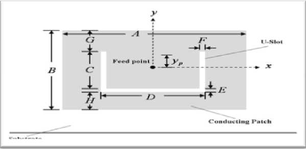
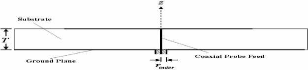
Fig.3.1. Geometry of the Rectangular U-Slot Microstrip Patch Antenna [9]
Table 1. Dimensions and Material Properties of the Initial U-Slot Antenna used in the Parametric Studies
|
A |
B |
C |
D |
E |
F |
H |
R |
T |
Offset |
ε r |
|
mm |
mm |
mm |
mm |
mm |
mm |
mm |
mm |
mm |
mm |
mm |
|
36 |
26 |
12 |
6 |
2 |
2 |
4 |
0.5 |
5.0 |
0 |
2 |
-
3.1. U Slot Position Variation along Positive Y Axis
-
3.2. U Slot Position Variation along Negative Y Axis
-
3.3. U Slot Position Variation along Positive X Axis
-
3.4. U Slot Position Variation along Negative X Axis
-
4. Results and Discussion
-
4.1. Results of Variation of Position of U Slot w.r.t. Positive Y Axis
-
This involves the variation of the position of the U slot along positive Y-axis. The variation is brought in the co-ordinates of the centre of the slot. Hence we can say that the position of the centre of the slot is varied. The last possible point along positive Y axis is (0,5). The U slot centre points are taken as (0,0), (0,1), (0,2), (0,3), (0,4) and (0,5). This variation of U slot results in change of the various parameters. The parameters like gain, resonant frequency are tending to degrade in their performance. Also the other parameters are also being affected by this variation.
Here the position of U slot is varied along negative Y axis. The last possible point along negative Y axis is (0,-5).The U slot centre points are taken as (0,-3), (0,-4), (0,-5). While moving from the origin towards negative axis, it is realized that the values of all parameters are changing.
This involves the variation of position of U slot along positive X axis. The variation of U slot is taken in the form of centre of U slot. The last possible point along positive X axis is (9,-2). The U slot centre points are taken as (1,-2), (2,-2 ), (3,-2 ), (4,-2), (5,-2), (6,-2), (7,-2), (8,-2), (9,-2).
Here the position of U slot is varied along negative X axis.. The last possible point along negative X axis is (-9,-2). The U slot centre points are taken as (-1,-2), (-2,-2 ), (-3,-2 ), (-4,-2 ), (-5,-2), (-6,-2), (-7,-2) , (-8,-2), (9,-2).
The centre of U slot is varied to various points along positive y axis and the antenna parameters such as frequency, return loss, gain and bandwidth are noted. The following graph shows the variation of U slot position and its effect on various parameters.
Fig. 4.1 and 4.2 represents the effect of U slot position on frequency and return loss of the antenna. Fig. 4.1 shows that as the centre of U slot is shifted away from the origin (0, 0) along positive y-axis, the resonant frequency shifts towards the upper end of frequency. Fig. 4.2 shows the degradation in return loss with increase of positive y axis.
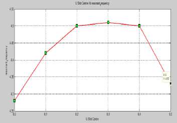
Fig.4.1. Plot of U Slot Centre and Frequency along Positive Y Axis
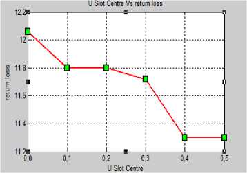
Fig.4.2. Plot of U Slot Centre and Return Loss along Positive Y Axis.
Fig. 4.3 and 4.4 represents the effect of U slot position on gain and bandwidth of the antenna. Fig. 4.3 shows that as the centre of U slot is shifted away from the origin (0, 0) along positive Y-axis, the value of the gain starts to decrease. Fig.4.4 shows the degradation in bandwidth with the shifting of U slot centre away from the origin.
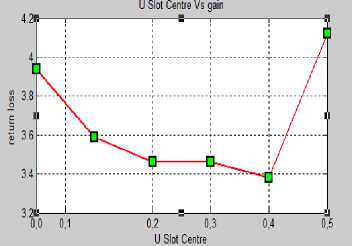
Fig.4.3. Plot of U Slot Centre and Gain along Positive Y Axis
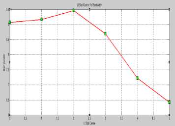
Fig.4.4. Plot of U Slot Centre and Bandwidth along Positive Y Axis
-
4.2. Variation of Position of U Slot w.r.t. Negative Y Axis
The second step is to vary the centre of U slot along negative y axis and note the output parameters such as frequency, return loss, gain and bandwidth. The following graph shows the variation of U slot position and its effect on various parameters.
Fig. 4.5 and 4.6 represents the effect of U slot position on frequency and return loss of the antenna. Fig. 4.5 illustrates the drop of resonant frequency towards the lower end of frequency while the centre of U slot is shifted away from the origin (0, 0) along negative Y-axis. Fig. 4.6 yields the better results in return loss with the shifting of U slot centre away from the origin along negative y axis.
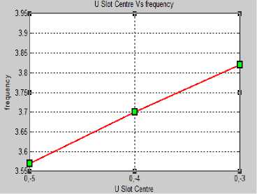
Fig.4.5. Plot of U Slot Centre and Frequency of Negative Y Axis
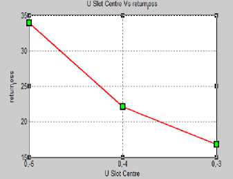
Fig.4.6. Plot of U Slot Centre and Return Loss of Negative Y Axis
Fig. 4.7 and 4.8 represents the effect of U slot position on gain and bandwidth of the antenna. In Fig. 4.7 it is shown that there is an increase of gain having the shift in centre of U slot away from the origin along negative Y-axis. Fig. 4.8 shows the degradation in bandwidth with shifting of U slot centre away from the origin along negative y axis.
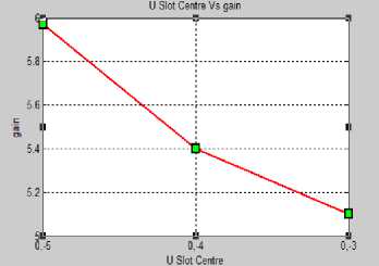
Fig.4.7. Plot of U Slot Centre and Gain of Negative Y Axis.
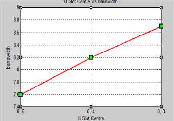
Fig.4.8. Plot of U Slot Centre and Bandwidth of Negative Y Axis
-
4.3. Variation of Position of U Slot w.r.t. Positive X Axis
The third step is to vary the centre of U slot along positive x axis and note the output parameters such as frequency, return loss, gain and bandwidth. It is observed from the variations that the variation of position of U slot gives better results. But these results are up to the U slot centre of (6,-2). After this point, the antenna performance degrades abruptly.
Fig. 4.9 and 4.10 represents the effect of U slot position on frequency and return loss of the antenna. Fig. 4.9 shows that as the centre of U slot is shifted away from the origin along positive X axis, the resonant frequency shifts towards the lower end of the frequency. Fig. 4.10 shows the better results in return loss with shifting of U slot centre away from the origin along negative y axis. But the better results of these parameters are up to the point (6,-2).
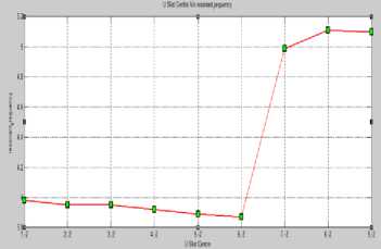
Fig.4.9. Plot of U Slot Centre and Resonant Frequency of positive X axis.
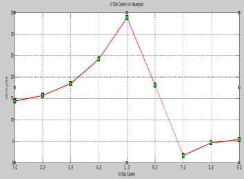
Fig.4.10. Plot of U Slot Centre and Return Loss of Positive X axis.
Fig. 4.11 and 4.12 represents the effect of U slot position on gain and bandwidth of the antenna. Fig. 4.11 shows the increase in gain with shifting of U slot centre away from the origin positive x axis. But this increase is up to the position at points of (6, -2). Fig. 4.12 shows the degradation in bandwidth with shifting of U slot centre along negative y axis.
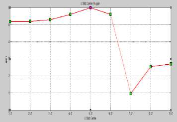
Fig.4.11. Plot of U Slot Centre and Gain of Positive X Axis.
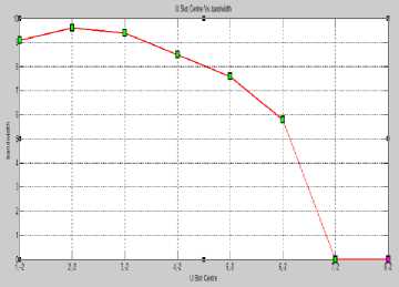
Fig.4.12. Plot of U slot Centre and Bandwidth of Positive X Axis.
-
4.4. Position of U Slot is varied w.r.t. Negative X axis
The next step is to vary the centre of U slot along negative X axis and note the output parameters such as frequency, return loss, gain and bandwidth. The following graph shows the variation of U slot position and its effect on various parameters.
Fig. 4.13 and 4.14 represents the effect of U slot position on frequency and return loss of the antenna. Fig. 4.13 shows that as the centre of U slot is shifted away from the origin along positive X axis, the resonant frequency shifts towards the lower end of the frequency. Fig. 4.14 shows the better results in return loss with the shifting of U slot centre away from the origin along negative y axis. But the better results of these parameters are up to the point (6,-2).
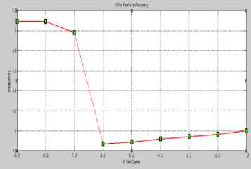
Fig.4.13. Plot of U Slot Centre and Frequency of Negative X Axis
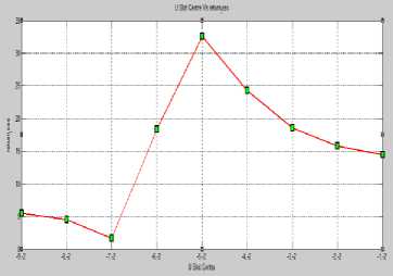
Fig.4.14. Plot of U Slot Centre and Return Loss of Negative X Axis
Fig. 4.15 and 4.16 represents the effect of U slot position on gain and bandwidth of the antenna. Fig. 4.15 shows the increase in gain with the shifting of U slot centre along negative x axis. But this increase is upto the position at points of (6, -2). Fig. 4.16 shows the degradation in bandwidth with shifting of U slot centre away from the origin along negative x axis.
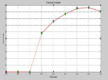
Fig.4.15. Plot of U Slot Centre and Gain of Negative X Axis
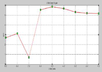
Fig.4.16. Plot of U Slot Centre and Bandwidth of Negative X Axis.
-
5. Conclusions
After this variation of U slot along all its axis it is concluded that The variation of position of the slot towards increasing positive y axis gives all the parameters degrading in their performance.
-
• With the variation of U slot along negative y axis, all the parameters are giving better results in their performance at the cost of bandwidth.
-
• The variation of U slot among positive X axis gives better performance of all its parameters. But this performance is up to some point (6,-2).
-
• With the variation of U slot among negative X axis, U slot gives better performance of all its parameters. But this performance is up to some point (-6,-2).
Therefore the results show that the variation of U slot position effects the antenna’s performance viz parameters like resonant frequency, gain, bandwidth.
In case of variation of U slot position along with all the axis, the best position has been analyzed where all the antenna parameters have improved performance. It is seen from the simulations that the optimal point of the variation of position of U slot centre is (0, -5) w.r.t. all the axis where the resonant frequency and return loss is reduced to 3.57 and -33.93 respectively. The gain increases upto 6dB.
References Numerical Analysis of Slot Position of Rectangular U Slot Microstrip Patch Antenna
- Balanis, C.A, Antenna Theory Analysis and Design, Wiley Publishers, (2005).
- Ansari, J.A. and Mishra, A. Analysis of L-Shaped Slot Loaded Circular Disk Patch Antenna for Satellite and Radio Telecommunication, Wireless Personnel Communication, (2012), vol. 70, pp. 927–943.
- Kumar, G. and Ray, K.P. Broadband Microstrip Antennas, Artech House, Waterhouse, R.B.J (2003).
- J. A. Ansari, R. B. Ram, and P. Singh. Analysis of a gap-coupled stacked annular ring microstrip antenna, Progress in Electromagnetics Research B, (2008) Vol. 4, 147–158.
- S. S. Yavalkar, R. T. Dahatonde. And S. S. Rathod. Parametric Study of Rectangular Microstrip Patch Antenna, IOSR Journal of Electronics and Communication Engineering (IOSR-JECE), (Mar. - Apr. 2013), Volume 5, Issue 2 pp 49-53.
- Surmeli, K. and Turetken, B .U-Slot Stacked Patch Antenna Using High and Low Dielectric Constant. Material Combinations in S-band, (2011).
- Uzer, M.S., Uzer, D., Yilmaz, N. and Gultekin, S.S. Bandwidth Modelling of U Slot Rectangular Microstrip Antenna with Artificial Neural Networks" Proceedings of Progress in Electromagnetic Research Symposium, Kuala Lumpur, MALAYSIA, (2012), pp. 559-563.
- Uzer, D., Uzer, M.S., Gultekin, S.S. and Yilmaz, N. Effect of U Slot Applications on Circular Microstrip Patches Modelling with Artifical Neural Network on Impedance Bandwidth, Proceedings of Progress in Electromagnetic Research Symposium, Kuala Lumpur, MALAYSIA, (2012), pp. 554-558.
- Weigand, S. and Huff, G.H. Analysis and Design of Broad-Band Single- Layer Rectangular U-Slot Microstrip Patch Antennas, IEEE Transactions on Antenna and Propagation, (2003), vol .51, No. 3, pp. 457-468.
- Tong, K.F. and Wong, T.P. Circularly Polarized U-Slot Antenna IEEE Transactions on Antenna and Propagation, (2007), vol. 55, No. 8, pp.2382-2385.
- Lee, K. F., K. M. Luk, L. Tongy, Y. L. Yung, and T. Huynh. Experimental study of the rectangular patch with a U-shaped slot IEEE International Symposium Dig., 10-13, 1996.
- J.A Ansari, P. Singh, and N.P. Yadav. Analysis of shorting pin loaded half disk patch antenna for wideband operation, Progress in Electromagnetic Research C, 2009 Vol.6, 179- 192.
- A. Rani, and R.K. Dawre. Design and Analysis of Rectangular and U slotted Microstrip Antenna for satellite Communication", International Journal of Computer Applications, 2010, Vol-12, No.7.
- Keith R. Carver and James W. Mink. Microstrip Antenna Technology IEEE Transactions on Antennas and Propagation, 1981, Vol. AP-29, No. 1.
- R. Arora, A. Kumar, S. Khan, S. Arya. Design Analysis and Comparison of HE and E Shaped Microstrip Patch Antennas International Journal on Communications Antenna and Propagation, 2014, Vol. 4, No. 1, pp. 27-31.
- D. M. Pozar, Microwave Engineering: Wiley Inter-science, 2006.
