
Numerical Simulation of Two-Phase Flow Dynamics in Counter-Current Swirl Separators: MultifactorAnalysis of Geometric and Operational Parameters
Журнал: Математическая физика и компьютерное моделирование @mpcm-jvolsu
Рубрика: Моделирование, информатика и управление
Статья в выпуске: 2 т.29, 2026 года.
Бесплатный доступ
This paper addresses efficiency optimization of centrifugal gas cleaning from fine particulate matter (PM2.5) in cyclone-type devices utilizing two opposing swirled flows. To unify various literature terms describing this hydrodynamic scheme – such as dual-vortex, opposed-swirl, or counter-current swirl configurations – we propose the comprehensive term “Counter-Current Swirl Separators” (CCSS). A defining physical feature of CCSS is the introduction of an axially swirled lower inlet stream that directly interacts with the upper vortex structure. The separation characteristics of the apparatus were evaluated using a combined computational and statistical approach. This methodology relies on a multi-factor design of experiments. In particular, a dataset of 60 numerical runs was generated via a maximin Latin Hypercube Sampling (Maximin LHS) strategy. This space-filling design provided data for a multi-dimensional sensitivity analysis. The cut-off diameter d50 was selected as the main objective function. The analysis covered joint variations of six key geometric and operational para- meters. As a result, the investigated factors were quantitatively ranked by their impact on fractional efficiency. The approach also revealed hidden masking effects and localized regions of non-linear system behavior during the vortex interaction. A comprehensive technical and economic criterion was introduced to evaluate the apparatus performance. This approach establishes a mathematical foundation for subsequent multi-objective optimization of the separator geometry. The resulting Pearson and Spearman correlation matrices confirm a predominantly monotonic response of the system within the studied ranges. These matrices define the validity boundaries for future continuous surrogate modeling.
Короткий адрес: https://sciup.org/149152110
IDS: 149152110 | УДК: 519.6 | DOI: 10.15688/mpcm.jvolsu.2026.2.3
Численное моделирование динамики двухфазных потоков в сепараторах со встречными закрученными потоками: многофакторный анализ влияния геометрических и режимных параметров
Работа посвящена повышению эффективности центробежной очистки газов от мелкодисперсных фракций (PM2.5) в сепараторах со встречными закрученными потоками (ВЗП). Для стандартизации терминологии в международной практике предложено использовать обобщающий термин Counter-Current Swirl Separators (CCSS). Динамика несущей фазы моделируется на основе стационарных уравнений Рейнольдса (RANS) с учетом модели переноса рейнольдсовых напряжений (RSM). Дисперсная фаза рассчитывается в лагранжевом приближении с помощью оригинального программного CUDA-модуля на GPU для непрерывного расчета траекторий ансамблей твердых частиц. Разработан новый метод оценки сепарационных характеристик ВЗП-аппаратов. В рамках единой методики объединены численные гидродинамические расчеты (CFD) и методы математической статистики на основе многофакторного планирования эксперимента. Использование методологии равномерного заполнения пространства параметров на базе оптимизированного латинского гиперкуба (Maximin LHS) позволило сформировать сбалансированную выборку численных экспериментов для динамики двухфазной среды. Выполнен многомерный анализ чувствительности целевой функции на основе медианного значения диаметра твердых частиц d50 посредством вариации шести управляющих геометрических и режимных параметров. Предложенная методология позволила количественно ранжировать исследуемые факторы по степени их влияния на фракционную эффективность. Выявлены скрытые эффекты маскирования второстепенных параметров доминирующими геометрическими характеристиками, а также локализованы области нелинейного поведения системы при взаимодействии встречных вихревых структур. В работе предложен и описан комплексный технико-экономический критерий эффективности аппарата, объединяющий аэродинамические и сепарационные параметры, что формирует математический базис для последующей многокритериальной оптимизации геометрии сепаратора. Полученные корреляционные матрицы Пирсона и Спирмена подтверждают преимущественно монотонный характер откликов системы в исследованных диапазонах и определяют границы применимости для последующего построения непрерывных суррогатных моделей.
Текст научной статьи Numerical Simulation of Two-Phase Flow Dynamics in Counter-Current Swirl Separators: MultifactorAnalysis of Geometric and Operational Parameters
DOI:
There are two main technologies for gas cleaning from solid particles. The first technology is based on inertial forces. The most effective method is separation due to rapid gas rotation in cyclones [16; 18; 22; 26; 27; 35; 48]. This is a rather economical, simple, and well-scalable method of gas cleaning. Particles with a diameter of d p) > 10 p m can be separated with an efficiency of up to 99 % [2; 49; 51]. The diameter interval of 2–10 µm represents a transition zone where the separation efficiency begins to noticeably drop to 40–85%, as the particle trajectories become heavily influenced by turbulent pulsations, vortex core precession, secondary flows, and other factors [39; 50; 51]. Increasing the efficiency requires adding complex curvilinear designs inside multichannel cyclones or the use of multi-cyclones [13; 21; 33; 37; 44].
For fine particles with a diameter of d^ < 5 pm, the cyclone demonstrates low performance because the separation efficiency can drop below 50%. Due to their extremely small mass, these particles behave almost like gas molecules. They follow all vortices and are easily carried out into the exhaust pipe. The cut-off separation diameter d 50 determines the size that is collected exactly by 50 %. The value of d 50 critically depends on the cyclone diameter D. In a first approximation, this relationship is determined by the dependence d 50 a D 1 / 2 . Therefore, only small-diameter high-efficiency cyclones can reduce d 50 to 2-3 p m. However, this approach requires significant energy consumption to create high static pressure [43; 56]. The quality of the gas-dynamic model is a defining factor in calculating particle trajectories and determining separation efficiency [9; 24; 39; 40]. Gas turbulence significantly affects the establishment of the mean velocity field and the level of the centrifugal force that ensures the quality of gas-solid separation [2; 3; 8; 50; 51].
An alternative approach for collecting submicron particles with a diameter under 1 µ m involves fabric baghouse filters. These filters are integrated into straight-through dust collectors [4; 53]. However, such systems feature high capital costs and significantly lower throughput compared to inertial analogs. Consequently, enhancing the efficiency of centrifugal separators through the introduction of new design modifications and the optimization of their operating parameters remains an urgent scientific and engineering task.
Thus, standard cyclone separation of PM2.5 and PM1.0 particles, which are critical to human health, yields poor results with efficiencies below 50%. The second technology is based on the use of baghouse filters. This method provides an efficiency of up to 99 % for PM2.5 and serves as the main industrial standard. However, the capital expenditures and operational costs of these filters are significantly higher. These costs include regular bag replacement, high energy consumption, and maintenance. A combination of these two technologies can solve the problem of PM2.5 collection while reducing the overall cost.
The most studied designs are classical cyclones with a global Rankine-type gas vortex [51]. Gas with a solid phase enters through one or more inlets in the upper part of the apparatus. The cleaned gas exits through the upper exhaust pipe [1; 6]. Another type of cyclone includes designs with two opposing swirled flows [6]. This scheme features a downward external flow from above. It also features an axially rotating gas from the lower inlet. The interaction zone of these two flows is a fundamental difference from classical cyclones. This second type of apparatus is still poorly represented in English-language studies. Various terms are used to describe these devices. These names include “Vortex Dust Collector (VDC)” [20; 30; 46; 57] and “Dust Collectors with Counter Swirling Flows (CSF)” [5; 14; 52]. Authors also use vortex dedusters “with counter-current swirled flows” [12] or even VZP as an abbreviation of the Russian transliteration [32; 55].
We propose to use the term “Counter-Current Swirl Separator (CCSS)” as it reflects the physical processes more accurately. The designation “Counter-Current” defines the structure of the flows that rotate in the same direction but move towards each other vertically. The use of the term “CounterSwirling” implies that two flows rotate in opposite directions around the same axis. This opposite rotation does not occur in the considered apparatus. A literature analysis shows that the term “Vortex Dust Collector (VDC)” currently leads in publication frequency with about 20 papers. However, the word “Vortex” in VDC completely hides the key physics of the process. Furthermore, the concept of a “Dust Collector” artificially limits the application of this technology solely to gas-solid separation. This term excludes gas-liquid separation tasks. Therefore, we use the term Counter-Current Swirl Separator (CCSS) below as it describes the hydrodynamic flow structure most completely.
The CCSS apparatus offers certain advantages [10]. However, the level of its fundamental understanding is incomparably lower than that of classical centrifugal dust collectors. Traditional cyclones are backed by thousands of publications based on large-scale physical and numerical experiments. In contrast, the field of CCSS remains poorly investigated. The use of modern computational fluid dynamics (CFD) for multiphase mediums to analyze CCSS performance and increase its efficiency is still extremely limited.
A characteristic feature of this field is the almost complete absence of CCSS technology in high-level Western scientific journals. Most published papers belong to scientists from Russia and the former USSR. This existing pool of publications is mainly local. The mathematical models and experimental depth often do not match modern global CFD standards. English-language publications by domestic authors on this topic include only a few dozen papers. These works are mostly presented in conference proceedings or translated versions of Russian journals. As a result, the CCSS technology remains isolated from the international scientific community. The lack of standard English terminology is additional evidence of the fragmented research in this area.
The optimization problem of classical cyclone geometry and its operational modes has an extensive literature [25; 26; 41–43; 48; 51; 56]. Similar studies for the CCSS focus mostly on applied optimization. These works cover only attempts to find relationships between individual parameters [6; 11; 12; 14; 55].
The aim of this work is to develop a method for the parametric analysis of Counter-Current Swirl Separators. The proposed method relies on multi-factor Latin Hypercube Sampling and system non-linearity estimation. This study also introduces a generalized technical and economic criterion for phase separation efficiency.
1. Computational model1.1. Simulations of two-phase flows
The dynamics of the two-phase disperse medium inside the CCSS are modeled within the classical Euler-Lagrange approach. The gas phase is treated as a continuous medium with a density % . The gas motion is described by the steady Reynolds-averaged Navier-Stokes (RANS) equations.
These equations express the conservation laws of mass and momentum
∂(%ui) =0, ∂xi where ui represents the components of the mean velocity for (i = x, y, z),
∂ ( %u i u j ) = ∂p + ∂
∂x j ∂x i ∂x j
µ
∂u i + ∂u j ∂x j ∂x i
ˆ
- %R ij
where p is the static pressure, µ is the dynamic viscosity. The variable R ˆ ij = u 0 i u 0 j represents the kinematic Reynolds stresses. Here, the prime symbol 0 denotes the fluctuating velocity component.
The closure of the system of equations is provided by the differential Reynolds Stress Model (RSM) [25; 42; 50; 51]. This model ensures an adequate description of strong anisotropic turbulence. We numerically integrated the governing RANS equations using the finite volume method. This procedure was performed within the ANSYS Fluent computational fluid dynamics software package.
The motion of the solid particle system as a disperse phase is modeled in the Lagrangian approximation using the Discrete Phase Model (DPM). The trajectory r(t) and velocity of each discrete m-th particle are calculated by integrating the equations d 2 rm dt
—pm + g + f add , m = 1,...,N (p) ,
τm drm %mdm2Cc where _n = m is the velocity of the m-th particle. The parameter Tp = — m---c represents the m dt m 18µ characteristic Stokes relaxation time of the particle. The variable Cc is the Cunningham correction factor. The parameter fadd is the additional specific force. This specific force accounts for various effects acting on a solid particle in a gas flow. These effects include the Saffman lift force, the Basset history force, the Magnus lift force due to particle rotation, and the pressure gradient force. The parameter Cc is introduced to refine the calculation of the Stokes drag force for submicron particles smaller than 1 µm.
1.2. Software package for modeling solid phase dynamics
Universal simulation packages inherently involve design compromises to maintain broad functionality. In steady-state CFD modeling, the built-in Discrete Phase Model (DPM) of ANSYS Fluent exhibits functional limitations that constrain the parametric analysis of counter-current swirl separators. To ensure high data resolution and accommodate specific hydrodynamic features of opposing swirling flows, a custom discrete phase simulation module was developed. This module integrates directly with the steady-state velocity fields exported from ANSYS Fluent, modeling the complete particle dynamics and overcoming the following key limitations of the standard DPM framework.
-
1) The built-in module does not allow for explicit determination of a fixed physical time interval for particle dynamics integration ∆ t mod = t end - t start . Instead, step control is managed indirectly through a combination of the ‘number of steps’ and ‘step length factor’ parameters. This introduces a complex, non-linear dependence of the interval ∆ t mod on local mesh discretization parameters, chamber geometry, and particle size fractions, which precludes rigorous time-dependent comparison of particle dynamics.
-
2) The architecture of the commercial software package is constrained to continuous trajectory
calculations, lacking the capability to export instantaneous state vectors of the particle ensemble.
This inability to record intermediate coordinates and velocities precludes step-by-step simulation restarts or dynamic runtime extensions. Access to these state vectors is critical for three primary reasons. First, this functionality is required to dynamically adjust discrete phase boundary conditions during the non-stationary or cyclic injections characteristic of industrial gas cleaning systems in electric arc furnaces and plant ventilation. Second, it is essential for modeling particle accumulation, coagulation, and deposition, which require tracking extensive particle rotations within localized dust ropes on walls or inside the top ash ring [29]. Third, an independent state-export capability simplifies the implementation of cascade multi-stage systems and optimization algorithms, allowing phase dynamics to be evaluated in isolated separator zones rather than across the entire computational domain. Under this decoupled framework, recording particle crossings through control planes generates downstream boundary conditions for alternative bottom-chamber geometries, thereby eliminating the need to repeat computationally expensive upstream trajectory calculations.
-
3) The standard simulation framework lacks explicit diagnostics regarding the final particle statuses, which are limited to basic trapped , escaped , or incomplete indicators. The detailed classification of these states is only possible through trajectory analysis using third-party tools. Consequently, identifying the physical mechanisms behind premature calculation termination or partial separation requires exporting and processing complete geometric trajectories, which substantially increases the computational complexity of the multi-factor Design of Experiments analysis.
-
4) Although recent versions of ANSYS enable Discrete Phase Model computations on the GPU, the extensive versatility of the Fluent architecture reduces parallel computing efficiency. The framework requires continuous data synchronization between the CPU and the GPU to evaluate diverse boundary conditions by transferring an Array of Structures containing all particle properties. Furthermore, execution within GPU warps is constrained by numerous built-in conditional branches because individual particles simultaneously occupy distinct physical states, such as free trajectories, wall reflections, porous media zones, or regions with high force gradients. This divergence of execution paths causes thread serialization, which significantly degrades GPU acceleration and forces the system into a lower-performance processing mode comparable to a standard CPU.
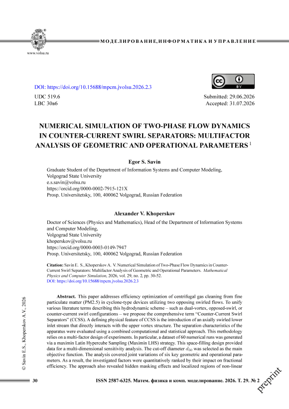
Figure 1 illustrates the software architecture developed for discrete phase dynamics modeling along with its external dependencies. The logical components are structured into four distinct subsystems. The import subsystem establishes the interface between the application and external CAD or CAE platforms by loading velocity fields and computational domain geometries. The optimization subsystem integrates components that substantially reduce the computational cost of the simulation process through the preprocessing of unstructured and irregular data. The computation subsystem executes all modules directly responsible for defining both the static and dynamic properties of solid particles as well as the phase interaction module handling particle-wall collisions. Finally, the export subsystem is designed to save intermediate particle states and compile comprehensive separation statistics.
Efficient parallel computing stands as a critical requirement when organizing large-scale simulations for multi-objective optimization tasks. The corresponding algorithm was implemented using NVIDIA CUDA technology. Figure 2 shows the CPU-GPU pipeline with the execution sequence and interaction between the CPU host and the GPU device. Within this diagram, rectangles represent specific computational stages, blue arrows show the transfer of control between modules, and green arrows show the direction of data transfer during CPU-GPU interaction. The logical blocks executed on different hardware components are grouped into the upper host section and the lower device section. The initial stage involves importing the input data. This is followed by particle system initialization and preparatory optimization steps. The next stage executes the iterative loop for particle trajectory computation directly on the GPU. At the end of each iteration, control transfers back to the CPU to advance to the next time layer and export particle state data if required. Upon completing the
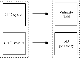
Discrete particle dynamics system
Computation subsystem
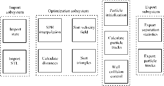
Fig. 1. Software architecture for discrete particle dynamics modeling within a gas velocity field trajectory calculations, the final stage performs the export of separation statistics.
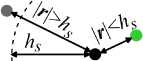
When a particle moves in a non-uniform flow, it is necessary to interpolate the gas velocity at the particle position. This procedure is executed at each integration step. The interpolation is based on the SPH approach, which is convenient for enabling operation with velocity fields on irregular meshes. The disadvantage is the high computational complexity O ( n · m) , where n is the number of particles and m is the number of mesh nodes of the velocity field. For this reason, algorithm optimization is required. The basic method involves using only a certain set of nodes within the smoothing length radius h s during interpolation via a smoothing kernel function. Figure 3 a shows this approach. Another important method consists in applying various sorting and nearest neighbor search algorithms to eliminate exhaustive search. This work uses a method based on cascade tables. Sorting is executed once for the velocity field. After that, a single sorted field is used for all particles.
Fig. 2. Interaction scheme between the central processing unit and the graphics accelerator
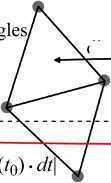
The correct detection of collisions between solid particles and the geometry of the simulated object is critical. Triangular meshes such as 3D models in STL format are used to define the geometry of the computational domain. We use an approach based on the Moller-Trumbore intersection algorithm to model the interaction of particles with solid walls. The triangles in the STL model are also sorted by the positions of their centers to avoid exhaustive search. The collision check itself is executed only when the particle is close to the wall. Figure 3b shows this procedure. For this purpose, the entire computational domain is pre-covered with a regular grid where the distances to the nearest triangles are stored in the nodes as distances(i,j,k). Further detection is performed provided that this distance is less than the displacement vector of the particle (distances(i,j,k) < Ud · dt).
a
b
dust particle ' Uf(x,y,z) ■ «
''..cellnode ,'' cell node
STL tri;
distances(i,j,K) e(iJ,k) cell node of distances array
dust particle 1
;distances(i,j,k)>m^2 (/o) * ^1
; dust particle 2
: ItteOoWI
4-----------
distances(i,j,k)<|L4/i (/q) •
Л|
C
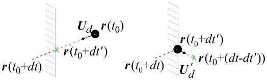
Fig. 3. Interaction scheme of a particle with irregular meshes: a – interpolation of the gas velocity field at the particle position using an SPH filter, b – criteria for initiating the collision check between a particle and a solid wall, c – processing of a triangle intersection by a particle displacement vector using local time-step truncation
The software implements an adaptive time-stepping system for particle integration. A global time step is defined for the entire system to govern velocity field updates and data export. In contrast, a local time step for each particle is calculated individually at each iteration based on its velocity, and further time-step truncation occurs during wall interactions. The collision of a particle with a solid surface involves momentum transfer via a restitution coefficient to simulate varying elastic properties of the dust and apparatus walls. Consequently, calculating the trajectory within a single time step becomes an iterative process.
Figure 3c shows an example of a solid particle interacting with a wall. If the particle trajectory intersects the structure surface, the integration step is truncated to a value dt0. This value is calculated using the Moller-Trumbore algorithm, and the particle is placed at the intersection point of its trajectory and the surface. Next, the gas velocity field is interpolated at this new position, and the equation of motion is integrated for the remaining time step dt - dt0. This iterative approach enables the modeling of multiple collisions. Thus, a variable number of adaptive local steps per particle can be executed within a single global integration step of the system.
2. Counter-Current Swirl Separators
Dry-type cyclone apparatuses can be divided into two classes [6; 51]. The first class includes classical cyclones. In these designs, one or more inlets at the top form the initial angular momentum of the gas. This feature remains a key property across various cyclone geometries. Figure 4 shows this variety of designs. The second class differs by having an additional inlet channel at the bottom along the axis of symmetry. The gas flow in this channel is swirled using special devices (Figure 5). Thus, there are two sources of gas swirl. One source provides the standard rotation of the peripheral part. The second source is created by the lower axial inlet. This formation of counter-current swirled flows is a distinctive feature of the second class of cyclones. CCSS devices began to spread later than classical cyclones. They were predominantly used in the USSR and CIS countries. This historical factor caused a certain imbalance in the volume of theoretical and experimental research. This is especially true for computational fluid dynamics studies. The number of CFD-DEM papers on classical cyclones reaches many thousands (see, for example, reviews [16; 17; 19; 27; 51]). In contrast, similar studies for CCSS using numerical simulations and semi-empirical approaches remain insignificant [7; 14; 28; 45].
These two types of designs create distinct flow structures of two-phase streams. The classical centrifugal cyclone forms a global Rankine-type vortex structure. This structure consists of a core region with a linearly growing rotation velocity U ϕ ∝ r . It also includes an outer quasi-free vortex region bounded by the wall. In this outer zone, the rotation velocity decreases as U ϕ ∝ r - n v for n v > > 0 [50] (Figure 4). Gas enters the upper part of the apparatus. This fluid forms a region of downward swirling medium along the walls. The flow reflects from the bottom. This reflection creates a vortex core of rising gas in the central zone. This rising gas leaves through the upper vertical pipe called the vortex finder. Gas can enter through several upper tangential channels. These channels create the angular momentum of the gas in the working zone. Crucially, this process results in a self-consistent Rankine vortex. This vortex exhibits different quantitative characteristics depending on the device geometry.
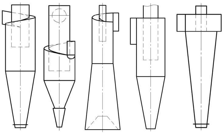
Fig. 4. Examples of different designs of classic cyclones [6]
The second type always has two or more inlet channels (Figure 5). Gas enters the apparatus from above with a velocity Ut(oinp) and a flow rate Q(tionp) . This fluid shifts downward in the outer zone closer to the walls. This behavior is similar to the classical cyclone case. However, another mandatory inlet pipe is located along the device axis. An independent rotating flow enters through this lower pipe. This counter-flow has a flow rate Q(bin) and an upward velocity Ub(in) . All gas similarly leaves the working chamber through the upper vortex finder. The presence of the lower swirled flow fundamentally changes the physics of gas motion. Instead of a wall-bounded Rankine vortex, there are two rotating flows. These streams move in opposite directions from two independent sources at the bottom and top. These flows can differ in gas velocity and flow rate.
We highlight three fundamental physical and structural differences based on the numerical simulation results.
-
1) In a classical cyclone, the gas and solid particle swirl decays during the downward movement. This attenuation occurs due to wall friction and turbulence. The flow is swirled only once at the upper inlet. In the CCSS, the lower inlet feeds the vortex as well. This counter-flow additionally swirls the medium in the lower part of the chamber. The equalization of the tangential velocity profile along the entire apparatus height weakens the vortex attenuation.
-
2) The second feature is the changed role of the dust hopper and the protection against particle reentrainment. The upward vortex in a classical cyclone contacts the collected dust in the conical part and the hopper. This process picks up fine particles from the bottom. These particles are then carried out into the exhaust pipe along the axial vortex core. A deep low-pressure zone forms in the center of the Rankine vortex. This zone creates a vacuum effect and sucks the gas upward from the bottom of the hopper. Together with the gas, the collected dust rises from the hopper. This phenomenon creates a significant secondary re-entrainment effect. In the CCSS, the lower upward vortex emerges from an independent pipe located high above the dust hopper. This stream creates a repelling effect that physically blocks the upper descending vortex from reaching the dust hopper, thereby completely eliminating the re-entrainment of the solid phase.
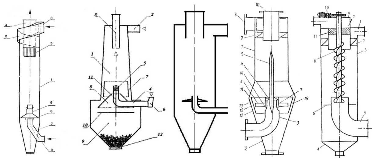
Fig. 5. Examples of different CCSS constructs [1]
-
3) The separation mechanism of fine fractions changes significantly due to the comprehensive reconstruction of the vortex structure, which represents a fundamental disruption when transitioning from a classical cyclone to the CCSS. In a classical cyclone, the unified global hydrodynamic system consists of a downward near-wall vortex that smoothly transforms into a central upward stream. This fluid movement results in the formation of a free vortex rope within the axial zone that reaches the very bottom of the separator. This vortex rope is subject to intense precession along its entire length, leading to continuous flow disturbances, a decrease in the particle settling velocity, and the secondary re-entrainment of fine dust from the lower section of the apparatus. Furthermore, the system experiences
distinct phenomena known as superbursts, which are associated with occasional strong interactions between the lower end of the vortex rope and the conical walls, thereby generating highly unsteady gas flow disturbances [50].
These phenomena, including precession and superbursts, completely disappear in the CCSS due to the impact of the independent lower rotating gas inflow. In the axial zone at the bottom, there is a total absence of a free vortex rope capable of reaching the lower part of the separation chamber, which stabilizes the flow structure and ensures a more effective separation of fine fractions without any risk of their re-entrainment into the upward stream.
Figure 6 illustrates the flow structure inside the CCSS for the base geometry, where a distinctive feature contrasting with a classical cyclone is the very weak rotation of the medium below the upper edge of the lower inlet pipe. This is especially noticeable within the conical part of the apparatus. The traditional application of a baffle disk in the form of an apex cone further suppresses the vortex structure in the lower zone. The axial low-pressure zone in a classical cyclone extends to the very bottom of the hopper, in contrast to the CCSS where this low pressure completely disappears in the area below the upper edge of the lower pipe due to the lower axial inflow.
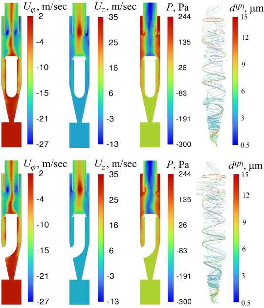
Fig. 6. Distribution of physical characteristics in the CCSS where the upper row shows the pressure, azimuthal velocity, vertical velocity, and solid particle trajectories in the xz plane, and the lower row relates to the yz plane
The azimuthal velocity field Uϕ exhibits greater asymmetry in the xz and yz planes due to the presence of the lower inlet pipe. The rotation velocity decreases significantly below the apex cone where the medium is in a quasi-static state, which creates favorable conditions for dust accumulation in the hopper. The axial velocity distribution Uz is also more uniform compared to a classical cyclone.
There are inverted V-shape axial velocity distributions with a single maximum of positive vertical velocity on the CCSS axis, while configurations with an inverted W-shape oran on-axis recirculation zone are completely absent, in contrast to the classical cyclone [50]. Large and medium particles moving downward in a spiral within the outer vortex fly past the apex cone and enter the conical part of the apparatus, slowly falling into the hopper, whereas fine particles perform many turns in the cylindrical part where their slower migration to the walls takes place.
3. Planning and conducting experiments based on the Latin hypercube3.1. Key factors and the Latin hypercube
The investigation of the hydrodynamics and separation characteristics of the CCSS involves significant computational costs due to the necessity of solving three-dimensional Navier–Stokes equations closed by differential turbulence models such as RSM or LES. The self-consistent solution of the discrete phase model equations further increases the requirements for computational resources. A high-quality optimization implies the variation of a large number of hypercube parameters N hc that determine the device geometry and its operational modes. In this study, we limit the choice to N hc = 6 with the total number of numerical experiments equal to N exp . Classical design of experiments approaches for N hc = 6 , such as full factorial design or central composite design, require an irrationally large number of simulations and lead to an inefficient filling of the inner regions of the parameter space.
Various space-filling designs are actively used in the modern practice of parametric analysis for complex computational systems to solve such problems [23; 31]. These approaches notably include deterministic Sobol sequences based on the quasi-Monte Carlo method and quasi-randomized algorithms that minimize multi-dimensional discrepancy [41].
A related approach involves the generation of experimental designs based on space-filling curve sampling, which utilizes fractal curves such as the Hilbert curve, Peano curve, and Morton order [54].
The Latin Hypercube Sampling (LHS) method is considered the most effective and universally recognized standard for constructing reliable surrogate models and conducting Pearson and Spearman sensitivity analyses [15; 36; 38]. The fundamental idea of this method is a strict requirement that the projection of the set of computational points onto any of the N hc coordinate axes must be distributed quasi-uniformly. Thus, each computational experiment is defined by a unique combination of parameters, which completely excludes the duplication of individual factor values on neighboring partitioning intervals. It is important to distribute the computational runs uniformly throughout the entire volume of the N hc -dimensional region without leaving any blind spots, as realized in the optimized LHS algorithm known as Maximin LHS. The original Latin hypercube method introduced in [38] relied on a random permutation of the matrix rows. In the optimized LHS approach, the initial random matrix is processed by a genetic algorithm or a simulated annealing method, shifting the points until they are distributed with perfect uniformity. Each computational experiment is defined by an N hc -dimensional vector of parameters
S ( j) = j , f j , f j , f j , f j , j , j = 1 ... N exp , N hc = 6
with a set of Euclidean distances
ρ
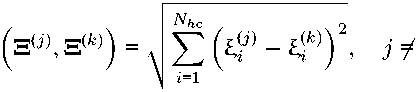
k
between any two unique computational points represented by the matrix rows j and k. The mathematical formulation of the maximin LHS criterion is to maximize the minimum distance max min ρ Ξ(j), Ξ(k) Ξ j6=k
This approach guarantees that all points of the hypercube repel each other, ensuring the most uniform and regular filling of the investigated parameter space without the occurrence of any local clustering.
The choice of key factors Ξ ~ = ( ξ 1 , ξ 2 , ξ 3 , ξ 4 , ξ 5 , ξ 6 ) for the LHS approach is discussed in this section. The diameter of the cylindrical part of the CCSS D , the height of the conical part H con , and the height of the dust hopper H dh are fixed at D = 0.15 m, H con = 0.3 m, and H dh = 0.2 m.
-
1) For apparatuses utilizing counter-current swirling flows, the balance between the upward and downward vortices is critically important. The most crucial operational characteristic of the CCSS is the flow rate ratio between the upper swirling flow Q ( t i o n p ) = U t ( o in p ) S top and the lower pushing flow Q ( b in) = U b ( in) S b . We limit our study to varying the velocity U b ( in) at a fixed value of U t ( o in p ) = 13 m/s, which yields the first LHS parameter defined as ξ 1 = U b ( in) /U t ( o in p ) varying within the interval of ξ 1 = = 0.38–1.15.
-
2) The second parameter is the relative diameter of the vortex finder defined as ξ 2 = D e /D , which varies within the interval of ξ 2 = 0.43–0.73.
-
3) The width b of the upper tangential inlet ata fixed velocity U t ( o in p ) and flow rate Q ( t i o n p ) determines the structure of the downward flow, which defines the third parameter as ξ 3 = b/D under the condition that a < H e . A violation of this condition leads to a sharp decrease in the collection efficiency due to the direct short-circuiting of even large particles into the vortex finder. For each point of the hypercube, the inlet height a must satisfy the relation a = 0.005 m 2 /b to maintain a constant area of the upper inlet, where ξ 3 = 0.2–0.45.
-
4) The relative diameter of the lower inlet defined as ξ 4 = D b ( in) /D must be coupled with the lower inlet gas velocity, where ξ 4 = 0.35–0.6. An excessive reduction of this diameter creates a concentrated jet that pierces straight through the core vortex. Conversely, an overly wide pipe scatters the counter-flow along the walls.
-
5) The length of the vortex finder to the top cover of the apparatus is denoted as H e . The relative immersion depth of this pipe, defined as ξ 5 = H e /D , ranging from 0.8 to 1.6 , must be strictly limited by the condition H e > a .
-
6) The relative distance from the lower edge of the vortex finder to the upper edge of the lower inlet pipe represents the sixth parameter, defined as ξ 6 = H int /D , where ξ 6 = 1.0–2.07 . This value determines the length of the active interaction zone of two vortices where the sign inversion of the axial gas velocity occurs and the interface surface between these flows develops.
The choice of the number of experiments N exp in the hypercube is often determined on the basis of the heuristic rule by J.L. Loeppky et al. [34]
N exp = 10N hc .
This rule of thumb is derived from a detailed analysis showing that the number of runs for an effective initial computer experiment should be approximately 10 times larger than the input dimension. For our case with N hc = 6 , this relation yields N exp = 60 . An additional strict geometric constraint of the design H e > a physically cuts off a certain part of the 6-dimensional space, which narrows the actual search space. Consequently, the distribution density of the remaining 60 valid points within this truncated volume remains high and effectively satisfies the rule (7). However, there are cases that require larger sample sizes in highly complex systems such as climate models [47].
Each row in the matrix of independent dimensionless factors Ξ of the LHS design defines a single simulation run, representing a unique point within the 6-dimensional parameter space of the hypercube. There is a strict geometric constraint H e > a that prevents any geometric overlap of elements. The axial height of the upper inlet pipe a for each experiment was calculated automatically from the condition of strict preservation of the inlet cross-sectional area S Op . This approach allows for an isolated investigation of the impact of the inlet pipe width ^ 3 at constant flow rates and velocity of the upper inlet stream.
Below we conduct a sensitivity analysis of the separator objective functions with respect to variations in the structural and operational parameters of the apparatus, which illustrates the behavior of the relationship between the input and output variables. The Pearson and Spearman correlation analysis shows the basic linear and monotonic relationships, respectively. The linear Pearson correlation coefficient is equal to riT =
E N exp j=1

-


j l ij-^l^
i = 1, 2,..., N hc ,
where T represents the objective function. This value indicates how strictly linearly a specific criterion T depends on the input factor ξ i .
The Spearman rank correlation coefficient r iS used to evaluate the monotonicity of the relationship between the factors and the response is calculated by the formula
. (S) i T
= 1 -
6 • P jN exp R (j - N exp ( Nexp —
R (T ( j)))
i = 1, 2, . . . , N hc ,
where R ^(j) j is the rank of the value of the i -th dimensionless factor in the j -th computational experiment, and R (T j j)) represents the rank of the corresponding value of the objective function T ( j) in the general ordered sequence of results.
3.2. Technical and economic efficiency criterion of the separator
Performance criteria can be based on the fractional efficiency, the hydraulic resistance of the apparatus ДР [48], and the turbulent kinetic energy that determines the risk of fine particle re-entrainment. An additive aggregation is very common for constructing such criteria because it transforms diverse physical quantities into a dimensionless form and sums them with specific weighting coefficients. The use of free weighting coefficients can be a major advantage of the criterion since it makes the mathematical model more universal. Varying these weights allows for tuning the optimization procedure for different types of industrial facilities. A strict environmental scenario provides for setting the cleaning efficiency weight to its maximum values if the enterprise is located inside a city where the penalties for PM2.5 emissions are severe. In this case, the energy consumption becomes a secondary factor. For example, another limiting case arises if the apparatus is used for rough primary cleaning at a remote quarry far from populated areas. In that situation, the energy consumption weight must be higher due to the necessity of saving the resource of diesel generators.
The optimal vector of the apparatus characteristics χ~ is determined through a comprehensive parametric criterion relationship. The objective function TF(~) approximates the total annual costs and environmental damage. The general design optimization problem is formulated as a search for the global minimum of the total objective function
min T f (X ) = T f i ( X ) + T f 2 ( ~).
χ~ where the costs due to hydraulic resistance are determined by the pressure drop ДР. The function in equation (10) includes the energy criterion defined as
Tf i ( X ) = ДР ( X)
Q τ T T el
1000 n vent
where η vent is the total efficiency of the gas fan providing the pumping of the two-phase medium through the cyclone. Theparameter η vent lies in the range of 0.60–0.75 depending on the concentration and dispersion of the solid phase. The variable Q represents the volumetric gas flow rate in m 3 / s, τ T is the operating time of the plant per year in hours per year, and T el denotes the electricity tariff in monetary units per kW · h. Thus, the objective function estimates the annual costs of the enterprise in monetary units per year.
The second factor in equation (10) is the environmental component T F 2 ( ~) expressed as a financial penalty for solid particle emissions into the atmosphere. The annual cost of the environmental damage or fines must couple the mass, the particle size distribution of the dust, and the separation efficiency n ( d (p) ) . The cost of the dust emission penalty is equal to
n

/ 1
1 - n ( d ( p) ,~)
Т^\~ ) = M(in\TTfine • X Am i • i=1
where M ( in) is the total inlet mass flow rate of dust in kg/h, and T fine represents the base economic penalty for emitting 1 kg of dust in monetary units per kg. A power function with the exponent β allows for adjusting the role of fine and coarse particles in the penalty calculations. Setting в > 0 increases the financial fines for the bypass of finer fractions. The value d base serves as a normalization factor. The simplest approach is to choose d base = 1 ^ m. Linking d base to the environmental standards of the PM2.5 or PM10 dust classification requires a readjustment of the parameter β because these variables are coupled with each other within the power function.
The appearance of the logarithm functions in equation (12) ensures the commensurability of the contributions from fine and coarse fractions. A linear consideration of the penetration defined as 1 — n creates an imbalance where the optimization algorithm exhibits high sensitivity to large-scale changes in efficiency for fine particles but completely ignores weak changes in the distribution of large diameters where n ^ 1 . The transition to the logarithmic scale ln( 1/ ( 1 — n )) transforms small changes in high efficiency into substantial increments of the objective function and shifts the evaluation from an absolute scale to a relative one.
Thus, we obtain a generalized parametric objective function for minimizing the operational and environmental costs of the cyclone, which includes a free control parameter β. The physical meaning of this value is discussed below.
-
1) The case of в = 0 corresponds to the evaluation of the net mass emission when coarse and fine dust are taken into account equally. The apparatus easily collects large heavy particles that contribute more than 90% of the total mass, and it does not create high resistance at a small pressure drop ДР .
In this case, the energy costs remain low, and the penalty for fine dust is also minimal because its total mass is insignificant.
2) An increase to β = 1 leads to the condition where the weight of the fractions is inversely proportional to the particle diameter. As a result, the contribution of 1 µm particles is enhanced by a factor of 10 relative to 10 µm particles.
3) The value of β = 2 yields a strong shift of the optimization priority toward the fine-disperse fractions where the financial penalty increases inversely proportional to the square of the particle diameter. The objective function optimizes the separator geometry by the total surface area of the emitted particles at a fixed total mass. This value represents an important indicator since hazardous toxic substances settle on the surface of the aerosol particles. An increase in this surface area determines a higher adsorption capacity with respect to these toxic substances. Therefore, the choice of β = 2 models a strict environmental scenario aimed at minimizing the medical and ecological damage caused by both PM1.0 and PM2.5 fractions.
4) The choice of β = 3 signifies a transition to the particle number distribution where the contribution of fine fractions increases by a factor of 1000 compared to coarse ones. The optimization focus shifts from a gravimetric evaluation to minimizing the absolute number concentration of the emitted particles. This scenario is highly relevant for the monitoring of ultrafine aerosols smaller than 1 µm that are capable of penetrating into human blood and tissues. Therefore, the parameter β = 3 defines the objective function for the most rigorous environmental standard where the main goal is to protect against submicron dust regardless of its mass.
3.3. Objective function of fractional separation efficiency
Thus, depending on the specific technological tasks and regulatory policy, the control parameter β can vary within the entire range of β = 0–3. At the same time, the interval of β = 1.5–2.5 represents the greatest practical interest for finding a rational compromise between the particle mass and particle number distributions.
For instance, several real industrial situations correspond to the model with β = 0 . First, environmental fines can be calculated on a gross basis without conducting a fractional analysis of the dust composition, where the objective function at β = 0 perfectly optimizes costs to meet the requirements of such legislation. Second, the recovery of valuable raw materials such as cement clinker, milk powder, or powder metals back into the technological cycle from drying or grinding units is determined solely by the total mass of the commercial product. Third, a rough primary cleaning stage in multi-stage systems is necessary to protect expensive baghouse filters from overloading, where the goal of the first stage is to separate the coarsest and medium dust to reduce the load on the final filter. Fourth, certain industries do not initially emit fine fractions. This case includes primary wood processing, the primary separation of grain dust, the collection of cotton or textile fluff during weaving and winding, cutting and garment manufacturing, and the primary mechanical cleaning of raw cotton.
The development of this performance criterion has an independent methodological significance. The two-factor objective function (10) with free weighting parameters integrates the analysis of hydraulic resistance and fractional efficiency into a single technical and economic problem. The non-linearity of the investigated space of six geometric and operational factors makes the direct CFD calculation of this criterion computationally inefficient for optimization algorithms. Therefore, the analytical description of the objective function establishes the necessary mathematical foundation for the subsequent construction of Kriging surrogate models to perform multi-objective optimization of the CCSS geometry.
For the primary analysis of the response space, we limit our consideration to a simple objective function defined as the cut-off separation diameter TF = d50 . This transition from a generalized criterion to an isolated physical characteristic allows for a detailed study of the phase separation hydrodynamics. The joint consideration of aerodynamic resistance and dust mass emissions at the initial stage can lead to a mutual masking of extrema. Determining the d50 diameter allows for evaluating the ability of the CCSS apparatus to retain fine dust regardless of weighting coefficients and cost tariffs. The obtained regularities form a foundation for subsequent multi-objective optimization.
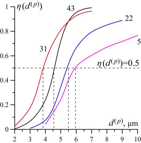
Fig. 7. Examples of fractional efficiencies for some points of the hypercube
Figure 7 shows the η ( d) dependencies for several experiments from LHS design. The condition η ( d ( p) = d 50 ) = 0.5 yields the d 50 value for each simulation run j = 1, ..., N exp . The results of processing these experiments are summarized in table ?? .
The dominant factor is the relative diameter of the lower inlet ξ 4 . The relationship d 50 ( ξ 4 ) exhibits a stable monotonic behavior and remains close to linear. An increase in the diameter of the lower inlet leads to a growth in d 50 . This deterioration in the cleaning quality is caused by a drop in the tangential velocity of the counter-current vortex at the inlet, which weakens the centrifugal force and promotes the re-entrainment of fine particles. The resulting monotonic trend indicates the necessity to expand the boundaries of the parametric analysis into the region of smaller values for ξ 4 < 0.35 , which will allow for a further increase in the separation efficiency. However, the search for the exact parameters of the technological extremum requires a dedicated numerical study to verify the moment when the stable counter-current vortex transitions into an unstable axial jet flow regime.
Values of the linear Pearson correlation coefficients r i T and Spearman rank correlation coefficients r (S) for the objective function T = d 50 .
|
Correlation criterion |
ξ 1 |
ξ 2 |
ξ 3 |
ξ 4 |
ξ 5 |
ξ 6 |
|
Pearson’s coefficient, r i T |
0.0177 |
0.2200 |
0.5638 |
0.6981 |
-0.3514 |
-0.2875 |
|
Spearman’s coefficient, r i ( T S) |
-0.0369 |
0.1743 |
0.5533 |
0.7004 |
-0.3700 |
-0.3554 |
The parameter ξ 3 represents the second most significant dominant factor. An increase in the relative width of the upper slot leads to a growth in d 50 and a decrease in efficiency. Conversely, a smaller value of b at a fixed gas flow rate and velocity enhances the separation quality. We highlight the main physical mechanisms of this observed effect. First, a narrow slot initially distributes the particles closer to the wall where the downward vortex layer develops. A thinner radial stream provides a better migration of the particles to the wall, which improves their overall deposition. Second, if the flow enters as a thin horizontal layer with a small parameter a and a large parameter b , a strong hydraulic expansion occurs along the vertical direction, accompanied by intense turbulent mixing and vortex dissipation. As a result, the gas with dust is ejected into the axial zone. Third, a decrease in b shifts the effective center of mass of the incoming jet closer to the apparatus wall. This shift increases the integral angular momentum of both the gas and solid phases, which favorably affects the migration of particles to the wall.
The parameter ξ 5 exhibits a negative correlation, and its growth contributes to a decrease in d 50 . However, an additional analysis revealed a masking effect caused by other factors. An overly short vortex finder leads to the short-circuiting effect accompanied by a low separation efficiency. Conversely, an excessively long vortex finder blocks the entire working chamber, which drastically reduces all the advantages of the CCSS and results in poor separation performance. Apparently, the chosen variation range in the hypercube lies entirely within the zone of a stable hydrodynamic optimum. The vortex finder already performs its main function within these boundaries, reliably cutting off the zone of direct gas short-circuiting from the upper inlet into the exhaust.
The relative diameter of the vortex finder ξ 2 shows a moderate positive monotonic relationship. Expanding this pipe reduces the rotation velocity, which enhances the dust mass re-entrainment by the gas flow.
The lower gas velocity ξ 1 also exhibits a weak positive correlation. From a physical perspective, the growth of the d 50 values with an increase in ξ 1 is explained by the fact that the excessive kinetic energy of the counter-current jet begins to intensively turbulize the interface surface of the interacting vortices. The emerging velocity pulsations partially inject fine-disperse fractions into the central upward flow, thereby increasing the dust penetration. The weak nature and stable positive sign of the obtained coefficients indicate that the investigated range of ξ 1 = 0.38 . . . 1.15 is located entirely on the ascending branch of the hydrodynamic dependence. The region of the optimal velocity balance for the opposing flows, which corresponds to the minimum of d 50 , is localized near the lower boundary of the DoE design where ξ 1 → 0.38 . This result allows for formulating a preliminary practical recommendation. The collection of submicron fractions requires tuning the apparatus to the minimum sufficient velocities of the lower inlet stream, which ensures the stable existence of the interface surface without its axial breakthrough.
The Pearson and Spearman coefficients are close to zero for the relative distance ξ6.A detailed analysis of the complete cloud of points shows that within the interval from 1.0 to 2.07, the relationship represents a flat band with a high vertical variance. This parameter does not exert any noticeable directional impact on the separation efficiency. The influence of ξ6 is masked and suppressed by the dominant factors ξ3 and ξ4, which proves the impossibility of optimizing the CCSS using simple one-dimensional or linear methods. The revealed autonomy of the parameter ξ6 allows for minimizing the total height of the apparatus to the lower boundary of the range where ξ6 → 1.0
while maintaining the separation quality.
Conclusion
A comprehensive approach combining high-fidelity CFD modeling and multi-factor statistical analysis is implemented for the parametric analysis of the hydrodynamics and separation characteristics of Counter-Current Swirl Separators (CCSS).
An original software architecture is proposed and verified in a Lagrangian framework based on CUDA technology to perform full calculations of the motion laws and trajectories of the discrete phase over the entire integration interval. The developed module successfully bypasses the limitations of the standard ANSYS Fluent DPM tools regarding the definition of physical integration time and the export of instantaneous phase state vectors, while providing additional capabilities for solid particle processing.
Analysis of the spatial distributions of physical property fields (pressure, azimuthal, and vertical velocities) demonstrates the advantage of CCSS apparatuses over conventional cyclones. The lower gas stream eliminates the centerline low-pressure zone and the corresponding gas vortex structure below the apex cone due to specific geometric design features. The formation of a quasi-static zone in the cone almost entirely prevents the secondary re-entrainment of solid particles from the dust hopper.
For the first time, the sensitivity of fractional separation efficiency to six control parameters simultaneously was quantified using the space-filling Maximin LHS design method. The calculation of Pearson and Spearman correlation coefficients allowed for ranking these factors by their degree of influence on the cut-off diameter d 50 and revealing the masking effects of minor geometric parameters by dominant ones.
The practical significance of the work lies in formulating constructive recommendations for designing high-efficiency PM2.5 separators. It is demonstrated that to minimize submicron dust penetration, the apparatus must be configured for the minimum sufficient lower inflow velocities and minimum diameters of the lower nozzle. The resulting dataset of consistent, monotonic DoE analysis data serves as the foundation for constructing continuous Kriging surrogate models to perform multiobjective techno-economic optimization of CCSS apparatuses.
Thus, an original generalized technical and economic efficiency criterion for CCSS apparatuses is proposed. Its mathematical structure is based on a joint analysis of energy consumption and media purification degree, expressed through a single cost equivalent. The introduction of free parameters allows for flexible adaptation of the objective function to specific production constraints. The obtained result forms a theoretical basis for the multi-criteria optimization of the separator geometry and operating modes without involving resource-intensive CFD simulations at each step of the optimization algorithm.
NOTE
1 The work was supported by the Ministry of Science and Higher Education of the Russian Federation (project FZUU-2026-0005).