On Design of Modified Hexagonal Slot UWB Antenna with Band Notched Characteristics

Author: Sampada C.Deshmukh, R.P.Labade
Journal: International Journal of Wireless and Microwave Technologies(IJWMT) @ijwmt
Article in issue: 4, 2017.
Free access
A micro strip-fed printed, modified hexagonal slot ultra wideband antenna with a band notch function is presented as well as investigated in this paper. The basic antenna comprises a U-shape radiating patch on one side of the substrate and ground plane with modified hexagonal slot on the other side of the substrate. Proper alignment and use of a modified hexagonal slot gives additional resonances and much wider impedance bandwidth is obtained. To create a notched band for WiMAX, symmetrical L- shape parasitic stubs are embedded in the upper edge of the modified hexagonal slot of the ground plane. The proposed antenna operates over the frequency band from 2.71 GHz to 11.73 GHz with a band rejection from 3.27-4 GHz (for WiMAX).The proposed antenna is fabricated on a FR-4 substrate having a dielectric constant of 4.4 with an overall size of 28 x 28 x 1.6mm3. Parametric studies have been conducted by changing length, width and thickness of symmetrical L- shape parasitic stubs. Simulated results are in good agreement with measured results. Designed antenna exhibits good radiation, efficiency greater than 80% within the entire ultra wideband except for WiMAX frequency.
Modified hexagonal slot antenna, ultra wideband (UWB), U-shape radiating patch, WiMAX
Short address: https://sciup.org/15012992
IDR: 15012992
Text of the scientific article On Design of Modified Hexagonal Slot UWB Antenna with Band Notched Characteristics
Published Online July 2017 in MECS DOI: 10.5815/ijwmt.2017.04.06
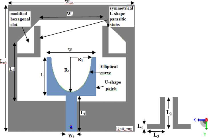
Fig.1. Geometry of proposed antenna
In [8], a planer slot antenna was proposed for UWB application along with dual-band-notch characteristics. They were notched WiMAX and WLAN by using parasitic slit. In [9], UWB antenna using a pair of L-shape slots in the ground plane is used for WLAN rejection, quarter wavelength slots and inverted L shaped slots for triple band notched characteristics [10]. In [11], the antenna operates at Bluetooth frequency along with band notch characteristics for WLAN band.In [12], antenna uses Land U-slot to create dual band notch characteristics for C-band satellite communication system and WLAN-band. To design an antenna for a transponder in radio frequency identification (RFID) different design of a novel approach is proposed [15].
-
2. Antenna Design and Analysis
-
2.1 Design parameters
-
Substrate (FR4) having dielectric constant 4.4 and thickness of 1.6 is used for manufacturing the antenna. The length and width of the micro-strip antenna is found by the formula given below [17].
Width of the patch is given by,
г
W = — х
4f r
Where C is the velocity of light in free space Effective Dielectric Constant:
£ 1 11.
£reff = 2 +
£У -
^
• 1
I2h ■ W
Length Extension: Extended distance ΔL along the dimensions of patch length and the normalized extension of the length is given by the equation,
AL _ 0.412(£re//+0.3)(^+0.264) h (£ re// -0.258)(^+0.8)
Effective Length:
C
L reff Г;
Length of Patch: Actual length of the patch is L p
Lp = L eff — 2AL
2.2 Band notch stub analysis
Symmetrical L- shape parasitic stubs are embedded at the upper edge of the modified hexagonal slot of the ground plane to create notch in WiMAX. The length of the symmetrical L- shape parasitic stubs are calculated by following formula.
L notch
C
Where

Optimized value of Lnotch=13.28mm and C is the velocity of light in free space.
-
2.3 Evolution of geometry
Firstly, the UWB antenna with an impedance bandwidth of 2.76 ~ 11.06 GHz is achieved as shown in Fig 2(a) which is printed on an FR4 substrate of thickness 1.6mm, loss tangent 0.02 and permittivity 4.4.It is fed by 50Ω micro-strip line. The antenna structure consists of a U-shape radiating patch in elliptical curve shape, having a radius of 4.5 and 8mm in x and y-direction, respectively, which is fed by 50 Ω micro-strip feed line, ground plane along with modified hexagonal slot. The patch has a width W and length L and it is connected to feeding line of width Wf and length Lf. Further, we insert symmetrical L- shape parasitic stubs on a ground plane having modified hexagonal slot to achieve band stop function as shown in Fig.2.(b). This provides band stop function for WiMAX band.
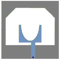
Fig.2. (a) The UWB antenna (b) Symmetrical L- shape parasitic stubs
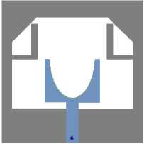
Table 1. Dimensions of proposed antenna
|
Configuration |
Parameter |
Value(mm) |
|
Substrate |
L sub (Length of the substrate) |
28 |
|
W sub (Width of the substrate) |
28 |
|
|
h (Substrate thickness) |
1.6 |
|
|
Patch |
W |
10.87 |
|
L p |
8.5 |
|
|
U-slot |
R 1 |
4.5 |
|
R 2 |
8 |
|
|
Modified hexagonal slot |
W 1 |
24 |
|
W 2 |
14 |
|
|
L 1 |
13 |
|
|
Symmetrical L-shape parasitic stubs |
L 2 |
6.98 |
|
L 3 |
5.5 |
|
|
L 4 |
0.8 |
|
|
Feed Line |
W f |
2.5 |
|
L f |
8 |
In this section, the single notch band modified hexagonal slot antenna with various design parameters is constructed. The simulated results are obtained using CADFEKO 7.0 software [18]. Fig.2.shows the various antenna geometries used for simulation studies. Reflection coefficient (dB) characteristics for the UWB antenna Fig.2. (a) and the symmetrical L- shape parasitic stubs Fig.2. (b) are shown in Fig.3.
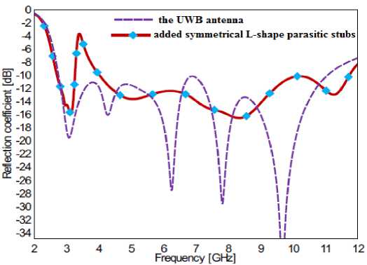
Fig.3. Simulated reflection coefficient characteristics for antenna shown in Fig.2.
From the above Fig.3., symmetrical L- shape parasitic stubs are used to provide band stop function for WiMAX. The red line indicates the reflection coefficient characteristics of proposed geometry. It shows that antenna operates over entire UWB with a band notch function. The parametric study has been conducted using the CADFEKO 7.0 simulation software. In the parametric study, the optimal value of each parameter (L1, L2, L3) was chosen and remaining parameters were optimized by fixing it.
Initially , the graph of length L 2 is varied by keeping L 3 and L 4 constant is shown in Fig.4.
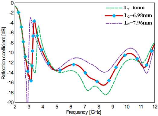
Fig.4. variations in parameter L2 of symmetrical L shape parasitic stubs
As the length (L2) increases, the higher edge frequency shift to lower side as shown in Fig.4. At L2=6.98mm, the band rejection property satisfies well at WiMAX. The graph of the variation in parameter L 3 of symmetrical L- shape parasitic stubs is shown in Fig.5. It shows that even though the width (L 3 ) change, the notching bandwidth remains same. The value of the thickness L 4 parameter was varied as shown in Fig.6. It is observed that as the length increases the band rejection goes on increasing .The results are better in L 4 =0.8mm.
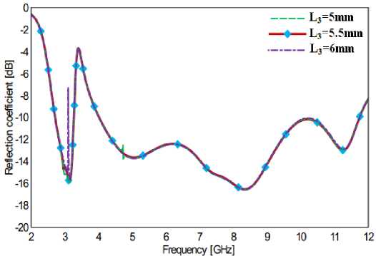
Fig.5. Variations in parameter L3 of symmetrical L shape parasitic stubs
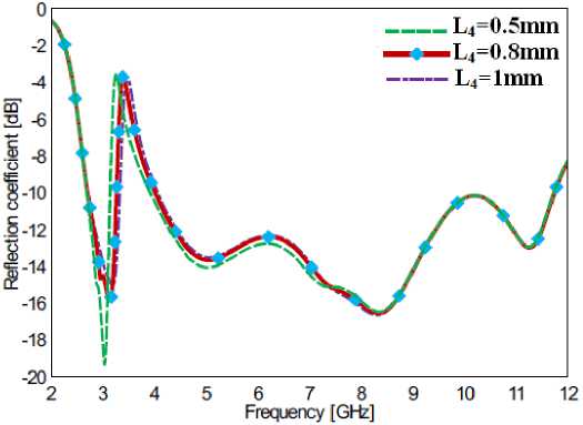
Fig.6. Variations in parameter L4 of symmetrical L shape parasitic stubs
From Fig.(4,5,6), it shows that there is no effect on the impedance bandwidth of antenna even though L 2 ,L 3 and L 4 are changed. This parametric analysis clearly shows the effect of symmetrical L- shape parasitic stubs on band notching characteristics. The effect of symmetrical L- shape parasitic stubs are observed in current distributions of proposed antenna at two different frequencies as shown in Fig.7. At un-notched frequency (5.09GHz) current distribution is dense as shown in Fig.7.(c,d).In Fig.7.(a,b) ,at the notch frequency (3.54GHz) current distribution is stronger and concentrated more along the symmetrical L- shape parasitic stubs. This shows that, symmetrical L- shape parasitic stubs are responsible for band notching characteristics.
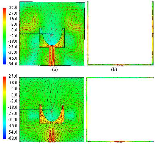
(c)
Fig.7. Current distribution inside slot (a) top view 3.54GHz (b) bottom view 3.54GHz (c) top view 5.09 GHz (d) bottom view 5.09 GHz
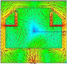
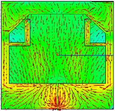
(d)
-
3. Results and discussion
The impedance bandwidth is measured using Agilent Field-fox Vector Network Analyzer (30 KHz to 14 GHz, Model No: N9916A), while the radiation pattern (E and H-field) measurements are carried out in an anechoic chamber. The simulated and measured reflection coefficient versus frequency of the proposed antenna is illustrated in Fig.8. The proposed antenna exhibits a band stop function for WiMAX, having a broad
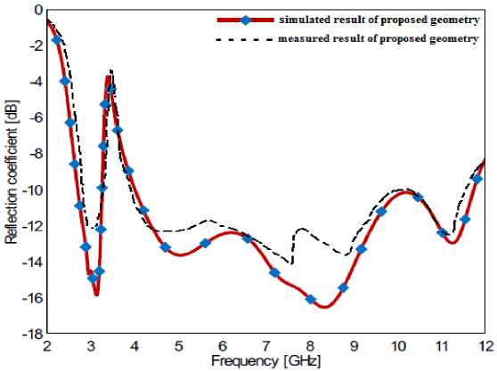
Fig.8. Simulated and measured reflection coefficient characteristics for proposed antenna.
impedance bandwidth of 2.71-11.73GHz for the reflection coefficient (S 11 ) <-10db. Simulated and measured results are in good agreement. The efficiency of proposed antenna is greater than 80% in the entire UWB band except WiMAX band as shown in Fig.9. At the notch frequency antenna efficiency drops sharply to 15%. Similarly, the gain of the antenna remains high except for notch frequency band (Fig.11.) shows clearly the band rejection characteristics of the antenna.
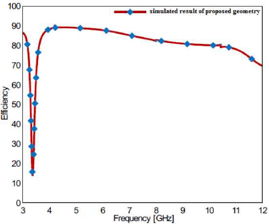
Fig.9. Simulated efficiency characteristics for proposed antenna.
Ludwig Ш(Сго$$)
Ludwig III(Co)
Measured
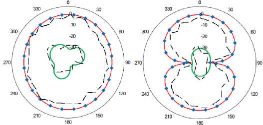
(a)
(b)

(e)
Fig.10. Simulated and measured radiation pattern of the proposed antenna at (a)H-field co and cross polarization at 4.02GHz (b)E-field co and cross polarization at 4.02GHz(c) H-field co and cross polarization at 5.09GHz (d) E-field co and cross polarization at 5.09GHz(e) H-field co and cross polarization at 6.95GHz (f)E-field co and cross polarization at 6.95GHz
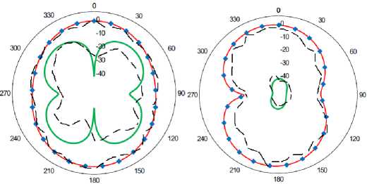
(f)
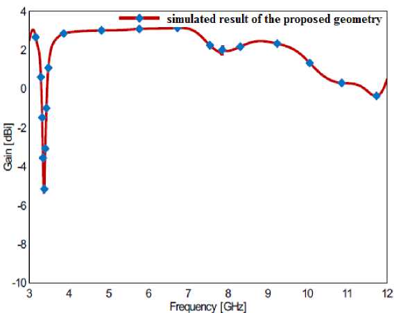
Fig.11. Simulated gain of the proposed antenna
Fig.10. shows the simulated and measured H-plane (x-z plane) and E-plane (y-z plane) radiation pattern of proposed antenna at 4.02GHz, 5.09GHz and 6.95GHz. It helps to demonstrate the antenna radiation property over the entire frequency band. It can be seen that the radiation pattern in H-plane is omnidirectional and dumbbell shape in E-plane. The cross-polarization increases with increase in frequency, however, it is less than -20db.
-
4. Conclusions
A compact modified hexagonal slot antenna with notched band characteristics has been proposed and investigated. Parametric studies have been conducted by changing length, width and thickness of symmetrical L- shape parasitic stubs. As the length L 2 increases, the higher edge frequency shift to lower edge and as width L 4 increases, the band rejection goes on increasing towards higher frequency .The proposed antenna provides a 9.02 GHz bandwidth (2.71 to 11.73GHz) for S 11 < ˗10 dB except for WiMAX (3.41~4GHz). By incorporating symmetrical L- shape parasitic stubs in the ground plane, the antenna shows good suppression ability of WiMAX band. The proposed antenna exhibits efficiency, greater than 80% and peak gain 3dbi , dumbbell shape and omnidirectional radiation pattern in E & H plane respectively, except the notched band shows the suitability of the proposed antenna for UWB applications.
References On Design of Modified Hexagonal Slot UWB Antenna with Band Notched Characteristics
- Federal Communication Commission(FCC),Washington, DC, “First report and order in the matter of revision of Part 15 of the commission’s rules regarding ultra-wideband transmission systems”, ET-Docket 98-153,2002.
- Daniel Valderas,Juan Iqnacio Sancho,David Puente,Cong Ling and Xiaodong Chen,“Ultrawideband Applications”,World Scientific Publication,London, 2011.
- Ghavami M.,Michael L.B.,and Kohno R,“Ultra-wideband Signals & Systems in Communication Engineering”,2nd edition, Wiley, New York,2008.
- Rekha P. Labade, Dr. Shankar B. Deosarkar, Dr. Narayan Pisharoty and Dr. Akshay Malhotra, “Printed Dual Band UWB Monopole Antenna with Tri Band Notched Characteristics for Wireless Communication”,International Journal of Microwave and Optical Technology, Vol.10, No.5, September 2015, 343-315.
- Sajad Mohammad ali nezhad, H.R.Hassani, Ali Foudazi, “A dual-band WLAN/UWB printed wide slot antenna for mimo/diversity applications”, Microwave And Optical Technology Letters,Vol.55,No.3,March 2013.
- Mohammad Ojaroudi and Nasser Ojaroudi, “Ultra-Wideband Small Rectangular Slot Antenna With Variable Band-Stop Function”, IEEE Transaction On Antenna And Propagation,Vol.02,No.1,January 2014.
- A.A.Kalteh, R.Fallahi and Golparvar Roozbahani“5-GHz Band-Notched UWB Elliptical Slot Antenna Fed by Microstrip Line”.
- Rezaul Azim, Mohammad Tariqul Islam and Ahmed Toaha Mobashsher, “Design of a Dual Band-Notch UWB Slot Antenna by Means of Simple Parasitic Slits”,IEEE Antennas And Wireless Propagation Letters,Vol.12,2013.
- Dang Trang Nguyen,Dong Hyun Lee,and Hyun Chang Park, “Very Compact Printed Triple Band-Notched UWB Antenna With Quarter-Wavelength Slots”, IEEE Antennas And Wireless Propagation Letters,Vol.11,2012.
- Sourabh Kumar,Shashank Verma,Abhik Gorai,Rowdra Ghatak, “Ultra-Wideband Antenna using Inverted L Shaped Slots for WLAN Rejection Characteristics”, International Journal of Computer Applications(0975-8887),International Conference on Communication, Circuits and Systems “ic3S-2012”.
- Rekha P. Labade, Dr. Shankar B. Deosarkar and Dr. Narayan Pisharoty “Compact Integrated Bluetooth UWB Band notch Antenna for Personal Wireless Communication”, Microwave and Optical Technology Letters, Vol 58, Issue 3, 540-546
- Ajay Yadav, Dinesh Sethi, Suman Kumar, Suman Lata Gurjar,“ L and U Slot Loaded UWB Microstrip Antenna: C-Band/WLAN Notched”, IEEE International Conference on Computational Intelligence & Communication Technology, 978-1-4799-6023-1/15 $31.00 © 2015 IEEE,DOI 10.1109/CICT.2015.99.
- G. Kumar and K. P. Ray, “Broadband Microstrip Antennas”, Artech House, 1992.
- FEKO user´s manual 7.0; May 2014.
- Omrane NECIBI, Abdelhak FERCHICHI Tan-phu VUONG, Ali GHARSALLAH “A Discussion of a 60GHz Meander Slot Antenna for an RFID TAG with Lumped Element” I.J. Wireless and Microwave Technologies, 2014, 2, 1-11.
