On Transforming Business Patterns to Labeled Petri Nets Using Graph Grammars

Author: Karima Mahdi, Raida Elmansouri, Allaoua Chaoui
Journal: International Journal of Information Technology and Computer Science(IJITCS) @ijitcs
Article in issue: 2 Vol. 5, 2013.
Free access
In this work we present an approach and a tool for transforming business patterns to labelled Petri nets. This transformation is justified by the fact that Petri nets have efficient analysis techniques. We specify first, business patterns and labelled Petri nets Meta-Models in UML Class Diagram formalism with the Meta-Modelling tool Atom3, and then we generate visual modelling tools according to the proposed Meta-Models. Finally, we define a graph grammar which transforms Business Patterns models to Labelled Petri Nets model for analysis purposes. The approach is illustrated with examples.
Business Patterns, Labelled Petri Nets, Meta-Models, Graph Transformation
Short address: https://sciup.org/15011808
IDR: 15011808
Text of the scientific article On Transforming Business Patterns to Labeled Petri Nets Using Graph Grammars
Published Online January 2013 in MECS
In the literature, there are many languages developed for modeling business process, each with its own tools and notations. They provide simple graphical representation but they do not support complex verification. The formal techniques provide better verification methods, but often, these models are too complex to be comprehensible by the human experts that have to validate them.
To avoid several and dangerous errors in business patterns models, many researchers proposed the mapping of business patterns to Petri net theory [1], which Provide a formal approach to process modelling. However, several patterns are difficult, if not impossible, to realize using this theory. Examples are patterns dealing with multiple instances, and advanced synchronization patterns. In [2] the authors proposed a deterministic Petri net language which implemented the main business patterns proposed in [3]. Therefore, the purpose of this report is to achieve this mapping automatically with the Multi-formalism and the MetaModelling tool Atom3 [4].
Atom3 was developed at the Modelling, Simulation and Design Lab in the School of Computer Science of McGill University, Written entirely in Python. AToM3 is a visual tool for meta-modelling and modeltransforming. Meta-modelling refers to modelling formalism concepts at a meta-level, and modeltransforming refers to automatic converting, translating or modifying a model of a given formalism into another model of the same or different formalism [3].
In this paper, we illustrate how Meta-Modelling is used to design business patterns (BP) and Labelled Petri Nets (LPN) meta-models then to transform BP models to LPN ones.
The remainder of the paper is structured as follows. In section 2, we discuss some basics of BP and LPN. In section 3 we propose a new approach for mapping BP models to LPN ones. In section 4, we apply the proposed approach on a BP model.
Finally, in section 5 we conclude this paper and present some directions for further research.
-
II. Background
-
2.1 The Basics of Business Patterns
-
2.2 The Basics of Labelled Petri nets
In the following, we recall some notions about business patterns, labeled Petri nets and the informal mapping between them.
A BP is a diagram composed of a set of activity nodes, denoting business events; and control nodes capturing the flow of control between activities such as AND-split, AND-join, XOR-split and XOR-join.
Activity nodes and control nodes can be connected by of a flow relation in almost arbitrary ways.
The patterns range from very simple patterns such as sequential routing to complex patterns involving complex synchronizations such as the discriminator pattern. The most relevant patterns can be classified into six categories [5]: Basic control flow patterns, advanced branching and synchronization patterns, Structural patterns, Patterns involving multiple instances, Statebased patterns and Cancellation patterns.
It is important to note that the means scope of our patterns is limited to static control flow.
A classical Petri net consists of places and transitions connected by arcs, places may contain tokens.
In [2] authors define a deterministic Petri Net language generated by a labelled Petri Net (LPN) as follow:
PN = ( N , т, ц0, F )
N = ( P , T , A ) is a Petri Net ,
P : a finite set of places ,
T : a finite set of transitions ,
A c ( PxT ) и ( TxP ) is the flow relation
( P n T ) = ф,
-
т: T----- >2 a labeling of T in the alphabet X,
-
2.3 An Informal Mapping of BP into LPN
Цр is the initial marking,
F is a set of final markings
According to definitions of BP and LPN (given in section 2.1 and 2.2), elements of Business diagram can be mapped to those of LPN like this:
V Activities can be modelled by transitions,
V Control nodes are modelled by places and/or by transitions (depending on the control nodes semantics),
V Activities are instantiated if the transition can fire; this is determined by tokens in LPN,
V The initial state of a BP model can be specified by the initial marking of the corresponding LPN model. A start event signals the start of a BP process. We hereafter put a token in the initial place of the LPN model.
-
III. Our Approach of Transforming Business Patterns to Labeled Petri Nets
-
3.1 Metamodel of Business Patterns
A meta-model of a given formalism specifies the syntax aspect of the formalism by defining the language constructs and how they are built-up in terms of other constructs. BP and LPN meta-models were created with the UML class diagram formalism of AToM3.
We have proposed the metamodel of Figure 1 for business patterns. It consists of four classes and two associations.
> The “BP_Activity” Class designs any business pattern activity; it has only one attributes “A_name” which denotes the name of the activity.
> The “BP_Connect” Class designs control nodes capturing the flow of control between activities such as AND-split, AND-join, XOR-split and XOR-join; it has only one attributes “C_name” which denotes the name of the connector.
> The “Init_Activ” Class designs the initial activity of the BP, it inherit from the “BP_Activity”.
> “From_Activ” and “TO_Activ” are two associations designing the input and output arcs of BP activities.
> The “Activ2Activ” association is used to create sequential activities.
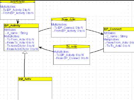
Fig. 1: The Business Pattern Metamodel
Finally, we define the Appearance property of each construct in accordance with the following notation.
|
Object |
Graphical appearance |
|
“BP_Activity” |
— |
|
“BP_Connect” |
--^BPJ>hne<^ |
When the metamodel is defined, we can generate the BP modelling tool (see Figure 2).
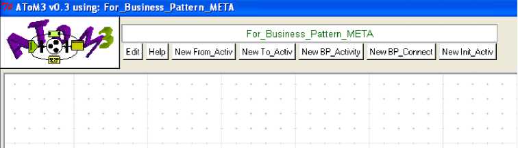
Fig. 2: A tool for manipulating BP
-
3.2 Metamodel of Labelled Petri Nets
We have proposed the metamodel of figure 3 for labelled Petri nets. It consists of two classes and two associations.
-
> The “PN_Place” Class designs any place in the LPN, it has two attributes the name of the activity “P_name” and the number of tokens in the place “Tokens”.
-
> The “PN_Transition” Class designs any transition in the LPN, it has one attribute the name of the transition “TName”.
-
> “PNIn” and “PNOut” are two associations designing the input and output arcs of LPN transitions.
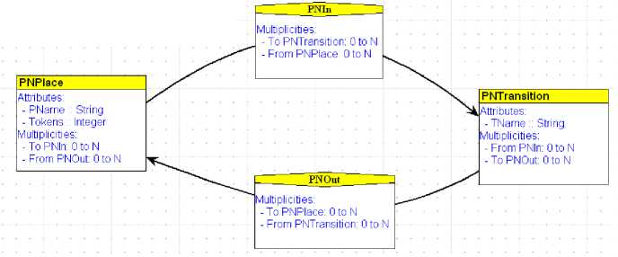
Fig. 3: The LPN Metamodel
-
3.3 Transformation of BP to LPN
Finally, we define the graphical appearance property of each construct according to the following notation.
|
Object |
Graphical appearance |
|
Object of “PN_Place” class |
/
\ |
|
Object of “PN_Transition” class |
|
When the metamodel is defined, we can generate the BP modelling tool (see Figure 4).
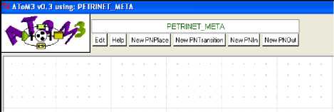
Fig. 4: A tool for manipulating LPN
In Atom3 model transformations are specified through graph grammars, and consist of Initial Action, Final Action and a Set of transformation rules. Each rule defines how to transform graph rewrite left hand side (LHS) to right hand side (RHS). LHS is a pattern which is matched against model being transformed; RHS is a graph that is inserted into the model instead of a matched Sub graph. The complete definition of a rule consists of: Name, Order, LHS, RHS, Condition and Action.
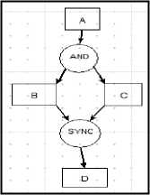
Fig. 5: A BP Model example
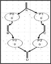
Fig. 6: LPN of the BP model of Fig. 5
To transform BP models to LPN ones, we have proposed a grammar with 20 rules. For example, to transform the BP model in figure 5 to the LPN model in figure6, we must execute the rules of our grammar in this order as follows:
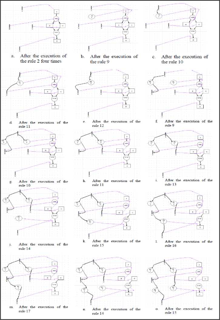
Now, we give the rules of the proposed grammar used in the previous transformation:
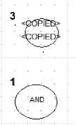
Rule 2 (priority 2):
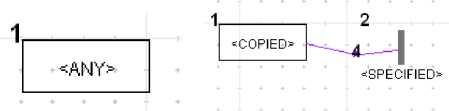
Fig. 7: (a) LHS of rule 2
(b) RHS of rule2
Brief Description: this rule is applied to attach each BP Activity (not previously processed) to a new LPN transition, and specified that the name of the attached transition is the same name of the corresponding BP Activity.
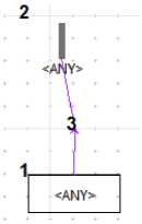
Brief Description: this rule is applied to locate an arc from an AND link to an activity in the model, and then create an Output Arc from the Place (attached to AND Link) to the Transition (attached to the Activity) . Also, this rule removes the Arc from AND Link to Activity.
Rule 12 (priority 12):
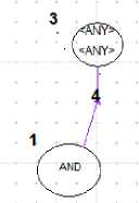
Fig. 11: (a) LHS of rule 12 (b) RHS of rule12
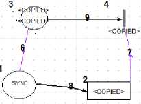
Rule 9 (priority 9):
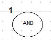
Fig. 8: (a) LHS of rule 9
(b) RHS of rule9
Brief Description: this rule is applied to remove generic link between AND connector and LPN place.
Rule 13 (priority 13):
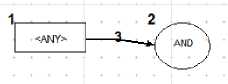
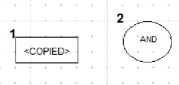
Fig. 12: (a) LHS of rule 13 (b) RHS of rule13
Brief Description: this rule is applied to Attach each BP connector AND to a new place.
Rule 10 (priority 10):
Brief Description: this rule is applied to locate an Arc from an Activity to an AND link in the model, and then removes it.
Rule 14 (priority 14):
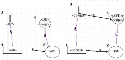
Fig. 9: (a) LHS of rule 10 (b) RHS of rule10
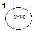
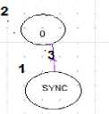
Fig. 13: (a) LHS of rule 14 (b) RHS of rule14
Brief Description: this rule is applied to Attach each BP connector SYNC to a new place.
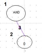
Brief Description: this rule is applied to locate an arc from an activity to an AND Link in the model, and then create an Output Arc from the Transition (attached to the Activity) to the Place (attached to AND Link).
Rule 11 (priority 11):
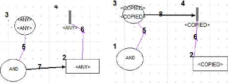
Fig.10: (a) LHS of rule 11
(b) RHS of rule11
Rule 15 (priority 15):
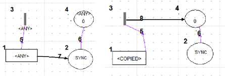
Fig. 14: (a) LHS of rule 15 (b) RHS of rule15
Brief Description: this rule is applied to locate an Arc from an Activity to an SYNC link in the model, and then create an Output Arc from the Transition (attached to the Activity) to the Place (attached to SYNC Link) . Also, this rule removes the Arc from Activity to SYNC Link.
Rule 16 (priority 16):
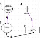
Fig. 15: (a) LHS of rule 16
(b) RHS of rule 16
Brief Description: this rule is applied to locate an Arc from an SYNC link to an Activity in the model, and then create an Output Arc from the Place (attached to SYNC Link) to the Transition (attached to the Activity).
Rule 17 (priority 17):
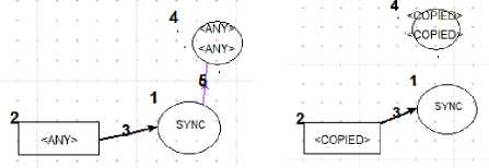
Fig. 16: (a) LHS of rule 17
(b) RHS of rule17
Brief Description: this rule is applied to remove generic link between SYNC connector and LPN place.
Rule 18 (priority 18):
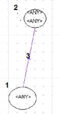
Fig. 17: (a) LHS of rule 18
(b) RHS of rule 18
Brief Description: this rule is applied to remove all the BP connector (linked by generic links to PN places) of the model.
Rule 19 (priority 19):
(a)
Fig. 18: (a) LHS of rule 19
(b)
(b) RHS of rule 19
Brief Description: this rule is applied to remove all the BP activities (linked by generic links to PN places) of the model.
Each rule in the grammar may have condition and action. The following lines give the condition and the action of the rule 2:
node._uniqueName8 = True pass
-
IV. Case Study
We have chosen a real example that was specified in Lotos in [6]. In this example, the system will check if the accident was already reported. If it is not the case, it will find the closest hospital to the accident. Then, it will concurrently send paramedics and a police patrol, before marking the accident as reported.
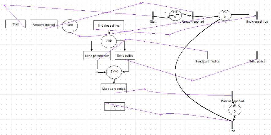
We have applied our tool on the case study of figure 19 representing a BP model created with our BP modeling tool. It contains Sequential patterns, Exclusive Choice pattern (XOR-Split), parallel split pattern (AND) and synchronization pattern (SYNC). The result of our model-transforming is the LPN model shown in Figure 20.
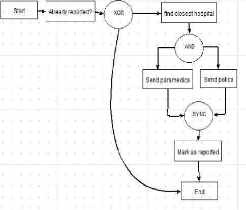
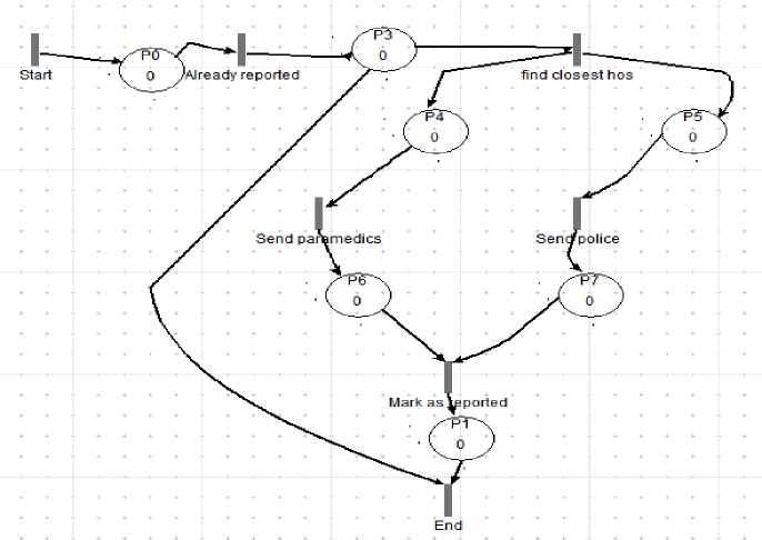
Fig. 19: BP Model of the case study

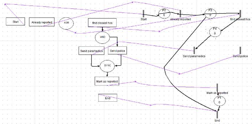
Fig. 20: LPN of the BP model of the case study
Now, we try to follow the transformation step by step:
Step1: rule 2 is applied 7 times for linking each BP activity to a PN transition with a generic link.
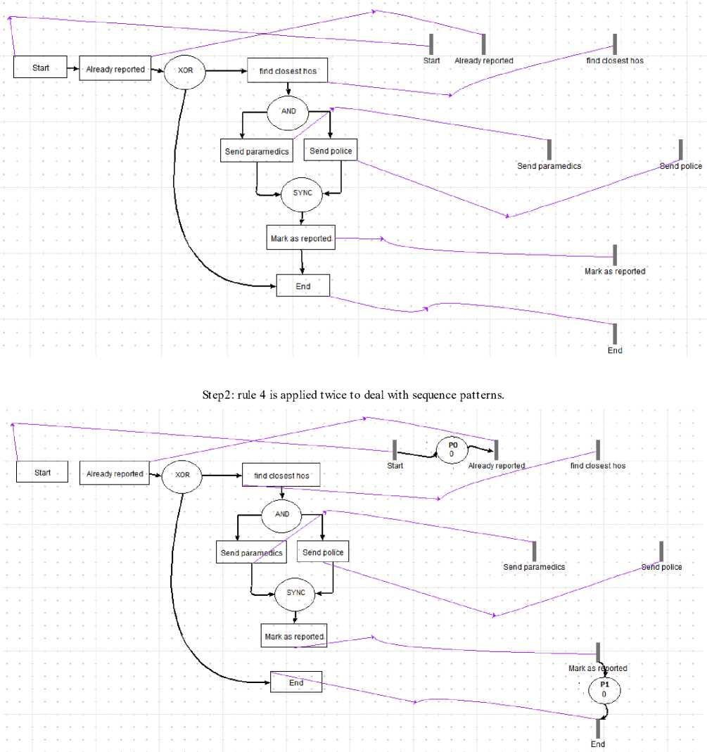
Step3: rule 5 is applied for creating a new place linked with generic link to XOR
Step 4: rule 6 is applied once because there is one input arc to XOR connector then rule 8 is applied twice to deal with the two output arcs of the XOR connector.
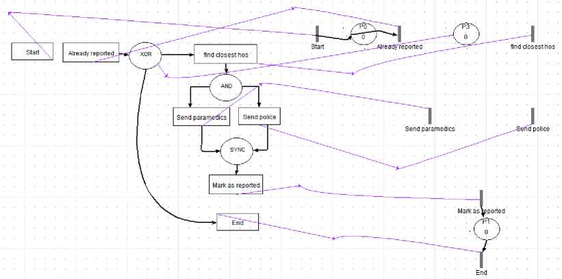
Step 5: rule 9 is applied for creating a new place P4 linked with generic link to the AND connector
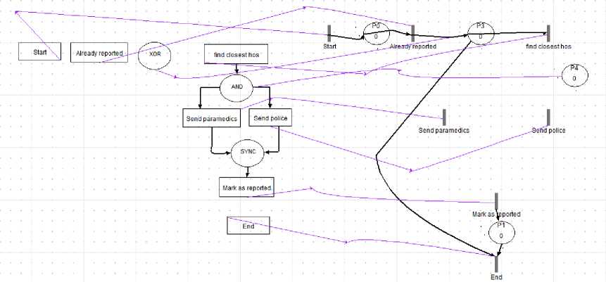
Step 6: rules 10 and 11are applied to deal with the input and output arcs of the AND connector
Step 7: rules 12 is applied to remove the generic link between the place P4 and the AND connector. We do this in order to process the other branches of the AND connector
Step 8: rules 9, 10 and 11ares applied deal with the other branches of the AND connector.
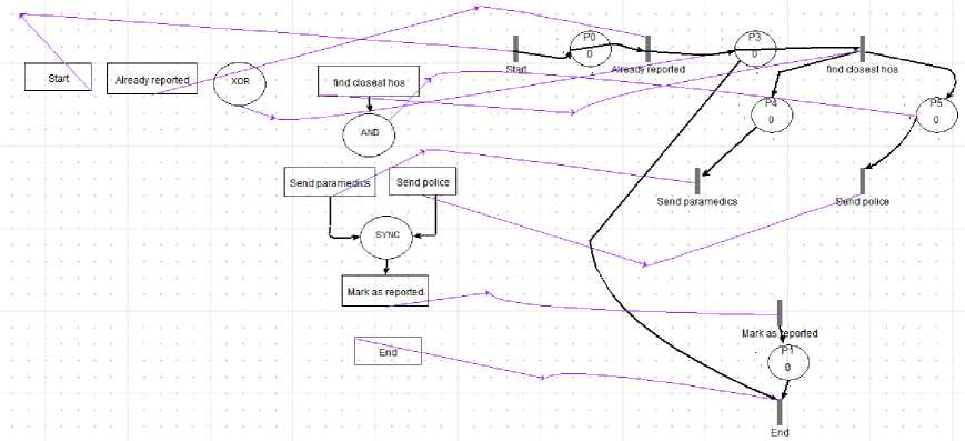
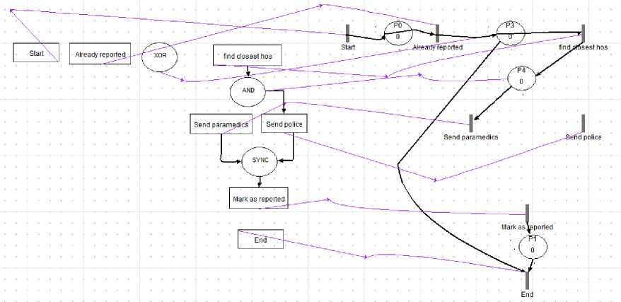
Step 9: it’s the end of the transformation of the AND connector, rules 13 is applied to remove the input arc of the AND connector
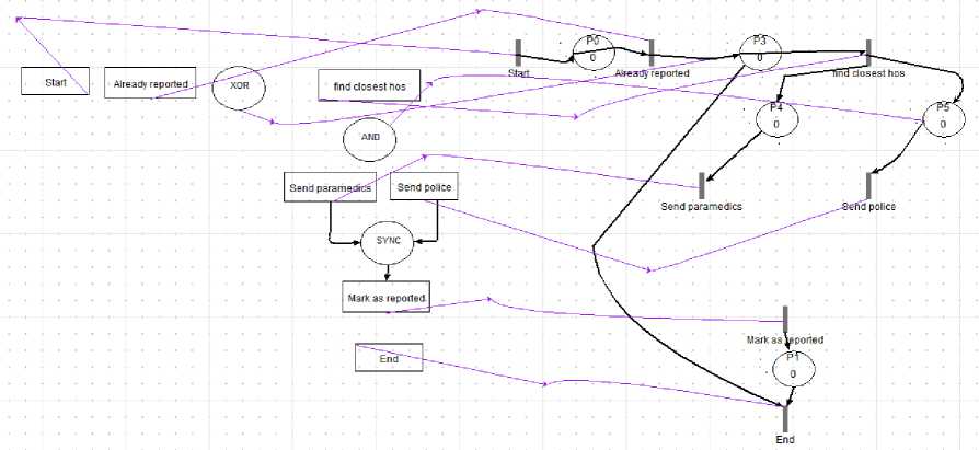
Step 10: we begin the transformation of the Sync connector . Rules 14 is applied for creating a new place P6 linked with generic link to the SYNC connector
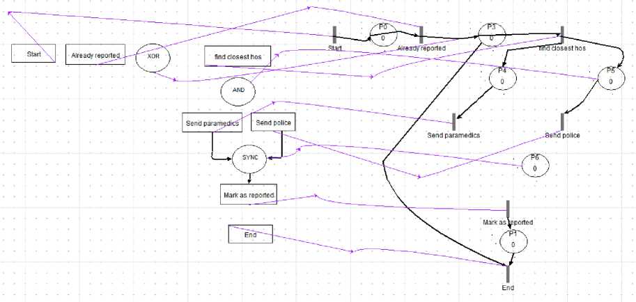
Step 11: rules 15 and 16 are applied to deal with the input and output arcs of the SYNC connector
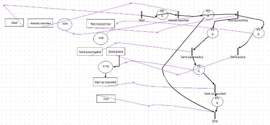
Step 12: rules 17 is applied to remove the generic link between the place P6 and the SYNC connector. We do this in order to pro cess the other branches of the SYNC connector
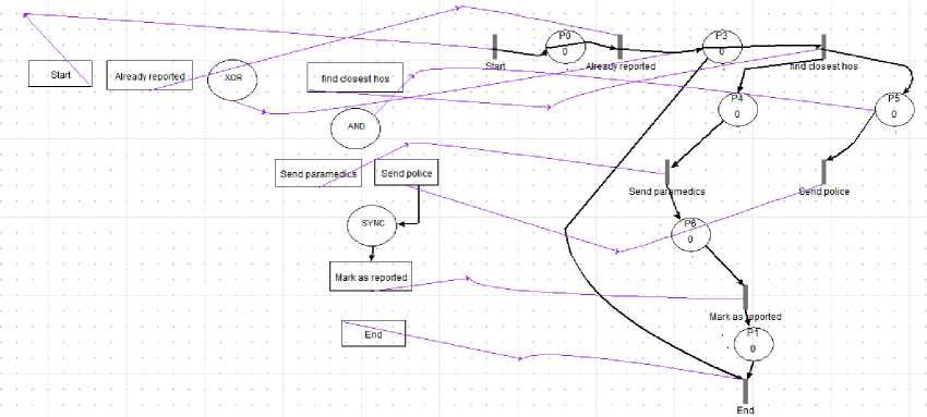
Step 13: rules 14, 15 and 16 are applied to deal with the other branches of the SYNC connector.
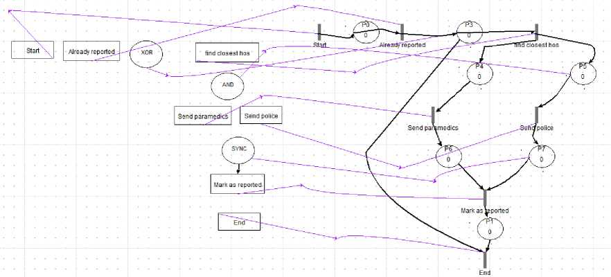
Step 14: Rule 18 is applied for 3 times in order to remove all the BP connectors of the model (XOR, AND, SYNC) then rule 19 is applied for 7 times in order to remove the seven BP activities of the model .
-
V. Related Work
There are many research works in the field of model transformation by graph grammars in the literature. In [7] the authors presented a transformation from Statecharts (without hierarchy) to Petri Nets. In [8], the authors have provided the INA Petri net tool [9] with a graphical environment. First, they have proposed a meta-model for Petri net models and used it in the metamodeling tool AToM3 to generate automatically a visual modeling tool to process models in INA formalism. Then they have defined a graph grammar to translate the models created by the generated tool to a textual description in INA language (INA specification). Then INA is used to perform the analysis of the resulting INA specification. In [10], we have presented a formal framework (a tool) based on the combined use of Meta-modelling and Graph Grammars for the specification and the analysis of complex software systems using G-Nets formalism. Our framework allows a developer to draw a G-Nets model and transform it into its equivalent PrT-nets model automatically. To perform the analysis using PROD analyzer, our framework allows a developer to translate automatically each resulting PrT-Nets model into PROD’s net description language. To this end, we have defined a meta-model for G-Nets formalism and another for PrT-Nets formalism. Then the meta-modeling tool ATOM3 is used to automatically generate a visual modelling tool for the two formalis ms according to their proposed meta-models. They have also proposed two graph grammars. The first one performs the transformation of the graphically specified G-Nets models to semantically equivalent PrT-Nets models. The second one translates the resulting PrT-Nets models into PROD’s net description language. In [11] we have proposed an approach for transforming UML Statechart and collaboration diagrams to Colored Petri nets models. More precisely, we have proposed an automated approach and a tool environment that formally transforms dynamic behaviors of systems described using UML models into their equivalent Colored Petri Nets (CPN) models for analysis purpose.
-
VI. Conclusion
In this paper we proposed an approach to automatically transform a BP with basic patterns to the equivalent category of Petri nets called LPN model. The approach is based on graph transformation and ATOM3 tool. In a future work we plan to adapt the proposed approach to deal with more advanced patterns and to integrate tools for Petri nets verification such as INA tool [9].
References On Transforming Business Patterns to Labeled Petri Nets Using Graph Grammars
- W.M.P. van der Aalst. 1968. The Application of Petri Nets to Workow Management. The Journal of Circuits, Systems and Computers, 8(1):21- 66, 1998.
- De Backer,M. and Snoeck, M. 2005. Deterministic Petri net languages as business process specification language. Dtew research report 0577, K.U.Leuven,
- Van der Aalst, W. M. ., A. H. M. ter Hofstede, B. Kiepuszewski, and A. P. Barros. Workflow patterns. QUT Technical report, FIT-TR-2002-02, 2002.
- De Lara, J. and Vangheluwe, H. 2002. ATOM3: A Tool for multi-formalism and meta-modeling. LNCS No 2306, 2002
- W.M.P van der Aalst, A.H.M. ter Hofstede, B. Kiepuszewski, and A.P. Barros.Workflow Patterns. Distributed and Parallel Databases, 14(3):5-51, July 2003.
- Dumez,C. Bakhouya,M, Gaber,J, and Wack,M. 2010. Formal Specification and Verification of Service Composition using LOTOS. Proceedings of the 7th ACM International Conference on Pervasive Services ICPS'10. ACM Computer Society Press, July (2010).
- De Lara,J and Vangheluwe,H.2002. Computer aided multi-paradigm modeling to process Petri-nets and Statecharts. International Conference on Graph Transformations (ICGT), Lecture Notes in Computer Science, vol. 2505, pp.239-253, Springer-Verlag, Barcelona, Spain,.
- El Mansouri,R. Kerkouche,E. and Chaoui,A. 2008. A Graphical Environment for Petri Nets INA Tool Based on Meta-Modeling and Graph Grammars. Proceedings of World Academy of Science, Engineering and Technology, ISSN 2070-3740, vol. 34, pp.471-475, October (2008).
- INA Home page http://www2.informatik.huberlin.de/~starke/ina.html
- Kerkouche, E. and Chaoui, A. 2009. A Formal Framework and a Tool for the Specification and Analysis of G Nets Models Based on Graph Transformation. International Conference on Distributed Computing and Networking ICDCN’09, LNCS 5408, pp. 206–211, Springer-Verlag Berlin Heidelberg, India, 3-6 January (2009)
- Kerkouche,E. Chaoui,A. Bourennane,E. Labbani, O. 2010. A UML and Colored Petri Nets Integrated Modeling and Analysis Approach using Graph Transformation. In Journal of Object Technology, vol. 9, no. 4 (2010), pages 25–43. Available at http://www.jot.fm/contents/issue_2010_07/article2.html
