Optimal Placement and Sizing of Capacitor and Distributed Generation with Harmonic and Resonance Considerations Using Discrete Particle Swarm Optimization

Author: M. Heydari, S.M. Hosseini, S.A. Gholamian
Journal: International Journal of Intelligent Systems and Applications(IJISA) @ijisa
Article in issue: 7 vol.5, 2013.
Free access
Presence of distributed generation (DG) in distribution systems has significant impacts on the operational characteristics of these systems, also using capacitor for reactive compensation and loss reduction is so common. Injected harmonic currents from non-linear loads into distribution system distort all of voltages and currents and must be considered when placing the capacitor banks so that the resonance will not occur. In this paper discrete particle swarm optimization (DPSO) approach is used for the optimal placement and sizing of distributed generations and capacitors in distribution systems for simultaneous voltage profile improvement, loss and total harmonic distortion (THD) reduction. There is a term in the objective function which prevents harmonic resonance between capacitor reactance and system reactance. Constraints include voltage limit, voltage THD, number/ size of capacitors and generators. For evaluating the proposed algorithm, the IEEE 33-bus test system is modified and employed.
Capacitor, Distributed Generation, Optimal Placement, Harmonic, Resonance, Discrete Particle Swarm Optimization
Short address: https://sciup.org/15010442
IDR: 15010442
Text of the scientific article Optimal Placement and Sizing of Capacitor and Distributed Generation with Harmonic and Resonance Considerations Using Discrete Particle Swarm Optimization
Published Online June 2013 in MECS
Centralized Power plants deliver the electricity to the end-user via transmission system. Distribution system makes a link between the high voltage transmission system and consumers. In distribution system, the voltage levels are low but current levels are high in the compare of transmission system, so the loss, in distribution system is greater than in transmission system. Most of loads connected to distribution systems are induction loads which make the system power factor will be lag and the voltage drop to a lower level even lower than the acceptable range. Any components connected to power system for working properly and safely must receive voltage in the defined range, any voltage out of this boundary can damage these components. In power system, operator is obligated to maintain voltage level of each costumer bus within the required limit. A most acceptable voltage variation is within the range of t 5% [1].
The rest of this paper is organized as follows: in section 2 modeling of network components at harmonic frequencies is discussed. Problem formulation for the objective function for improving voltage profile and minimization of loss and THD is presented in section3.In section 4 the pso algorithm is described briefly. The results of DG and capacitor placement on 33-bus test system are presented and discussed in section5. Finally, section 6 summarizes the main points and results of this paper.
-
II. Model of Network Components at Harmonic Frequencies
-
2.1 Cable
-
2.2 Transformer
-
2.3 Capacitor and Inductor:
In this paper for modeling of network components at harmonic frequencies, some practical and approximation of references [16,17] is used.
For very accurate model of cable at high frequency some modifications need to be applied to the resistance and inductance of cable. But for practical harmonic analysis a simple model is enough. For the h harmonic order the line impedance can be written as:
Z( ) =R +jhX (5)
Because of non-linear magnetizing properties of transformer it is difficult to model it at harmonic frequencies and because of core saturation it produces harmonic itself. For harmonic study in this paper we assume transformer operates in normal condition. So the impedance of transformer at harmonic frequency can be written as:
Z( ) =R +jhX (6)
Capacitor and inductor can be modeled similarly and their impedance at harmonic frequency can be expressed by:
Χ = 1 ⁄2πhfc (7)
-
Χ = 2πhfL (8)
where f is the main frequency of the system.
-
III. Problem Formulation
-
3.1 Constraints
In this paper the following assumptions are made:
> Capacitors are fixed type.
> Both linear and non-linear loads are presented in a balanced 3-phase system.
Voltage constraint will be defined as follows:
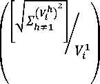
≤√ ( ) ≤
where V is lower , V is upper bounds of rms voltage and V is h harmonic order of voltage at bus i . In this paper V =0.95 and V =1.05.
THD:
Total harmonic distortion of voltage (THD) should be less than the maximum of allowable
≤
, =
max v
In this paper according to IEEE-519, THD =0.05.
-
3.2 Indexing
-
3.2.1 Voltage deviation index
For forming of objective function some indexes are defined.
This index is for improving of voltage profile and defined as follows:
∑ -
( ) (11)
. _ чиут
Where V is the nominal of system voltage
(V =1) , V is the voltage at node i and n is number of busses.
capacitors which make resonance will be omitted automatically in the minimization progress of the algorithm.
3.3 Objective Function
By introducing above indexes objective function is defined as follows:
3.2.2 Active and reactive power loss index (PL-I, QL-I)
- =
‘L—MO
- =
Ql Ql-no
F=αVD-Ӏ+αPL-Ӏ+αQL-Ӏ
+αTHD-Ӏ +αRES-Ӏ (16)
where α is the index weight, these weights indicate the importance of each index in the placement problem. They depend on the required analysis.
Where P , Q are active and reactive power losses after installation of DG and capacitor respectively and P , Q are active and reactive power loss before installation.
∑α=1
α ϵ [0 1] 3.2.3 THD index In table 1 these weights is defined, for selecting these weights, the guides of [19,20] is used. This index is for minimizing of total harmonic distortion: n THD-Ӏ=∑max(0,(THD-THD )) (14) i=l Where THD is the total harmonic distortion of bus i. Table 1: index weights
index
Index weight
value
VD-I
аг
0.3
PL-I
«2
0.2
QL-I
«3
0.2
THD-I
d4
0.15
RES-I
«s
0.15
3.2.4 Resonance index (RES-I)
Many works concerning capacitor placement, consider all loads are linear, recently some works take non-linear loads into account, so the capacitor placement problem mixed with harmonic consideration, but as it is shown in [18] even in these works, capacitor placement led to harmonic resonance at one or some harmonic frequencies. In this paper there is a term in the objective function which prevents harmonic resonance. So resonance index is defined as follow: RES-Ӏ n m =∑∑(V /V ) i=l h=l + n m ∑∑(I /I ) i=l h=l Where V , I are the voltage and current of bus I at h harmonic order after installation and V , I are before installation of DG and capacitor. When resonance occurs, voltage or current at resonance frequency will increase and may go much more than the nominal amplitude of main frequency. So if resonance occurs, the amplitude of this term will increase and
IV. PSO Algorithm
Particle swarm optimization is an algorithm developed by Kennedy and Ebhart. This algorithm is based on social behaviors of bird flocking or fish schooling and the methods which they use to find food sources. In a simple way this algorithm is defined as follows:
>
The search space is d-dimensional
>
Particle: Each member is called particle and is presented by d-dimensional vector and described as:
=[ , ,…,……, ] Where Χ is the (I-th) particle.
>
Population: a set of n particles in the swarm is called population and described as:
pop=[Χ,Χ ,……,Χ ]
>
pbest: the best previous position for each particle is called particle best (pbest) and described as:
pbest = [pb ,pb ,……․,pb ]
>
gbest: the best position among all of particle is called global best (gbest) and described as:
gbest = [gb ,gb ,……․,gb ]
>
velocity: the rate of position change for each particle is called particle velocity and described as:
=[ , ,……, ]
>
updating velocity: at iteration k the velocity for d-dimension of i-particle is updated by:
V = wv + c r (pd - x ) +c r (gb -x ) (18) Where w is the inertia weight, c and c are the acceleration constants, and r , r are two random values in range [0,1]. The acceleration constants ( c , c ) control how far a particle will move in a single iteration. Typically these both are set to a value of 2. The inertia weight (w) is used to control the convergence of behavior of pso. Small values of (w ) lead to more rapid convergence usually on suboptimal position, but large value may prevent divergence. In general the inertia weight is set according to the following equation: (w -ԝ ) w = w - ( ). iter (19) iter
>
updating position:
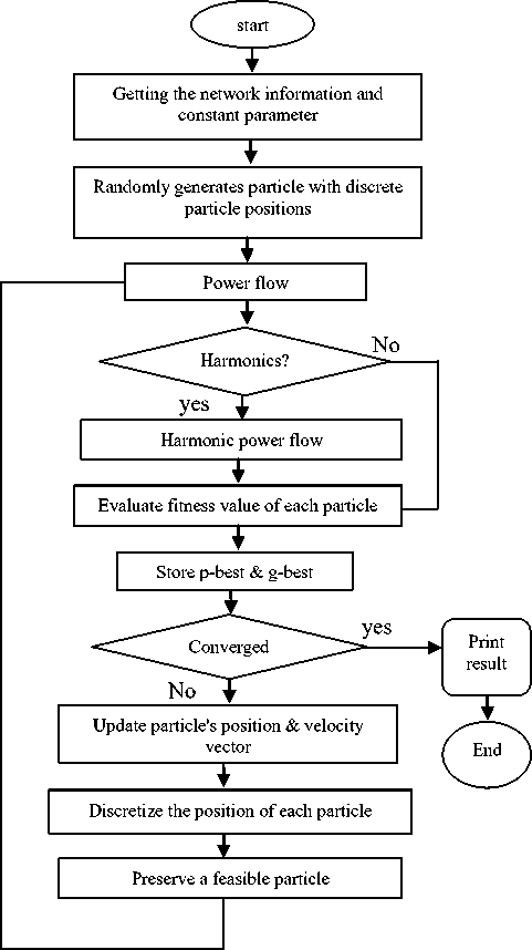
The i-particle position is updated by: = + (20) Fig. 1: flowchart of pso algorithm For binary discrete search space, Kennedy and Ebhart [21] have adopted the pso to search in binary space by applying a sigmoid transformation to the velocity component given in (21) to squash the velocities into a range [0,1],and force the component values of position to be 0 or 1. The equation for updating positions in (20) then is replaced by (22)
sigmoid(v ) =
1
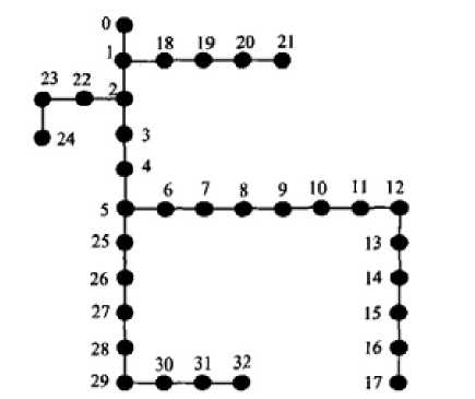
1+e ={1 < ( ) , 0 ℎ ℎ } (22) V. Simulation Results: The presented algorithm was implemented and coded in Matlab computing environment. In order to evaluate the proposed algorithm, the 12.6 kv 33-bus IEEE distribution system is modified and applied, such that the objective function given in [16] is minimized. The single diagram of this system is shown in Fig.2. The specification of this system is given in[22] .two nonelinear loads are replaced with loads in buses 5 and 26.This loads are two six-pulse converter with active and reactive power of 1MW and 0.75MVAR.the harmonic current spectra of these converters is given in table 2. Fig.1 shows the flowchart of this algorithm Fig. 2: single line diagram of 33-bus IEEE distribution system Table 2: six-pulse converter harmonic spectra
Harmonic order
Percentage of harmonic current
1
100
5
20
7
14
11
9
13
8
17
6
19
5
23
4
25
4
Capacitors and Distributed generations are commercially available in discrete sizes. In table 3and 4 the size of capacitor bank and DG are given: Table 3: capacitor sizes
Capacitor size(kvar)
Capacitor size(kvar)
Capacitor size(kvar)
150
1500
2850
300
1650
3000
450
1800
3150
600
1950
3300
750
2100
3450
900
2250
3600
1050
2400
3750
1200
2550
3900
1350
2700
4050
Table 4: DG sizes
DG SIZES(KW)
100
300
800
3000
5000
In table 5, rms voltages and THD of all buses for the base case (no installation) are demonstrated. As observed in table 5, the voltage level of some buses drop to level lower than acceptable limit and THD of some buses go to level higher than upper limit of defined range by IEEE-519 standard. Table 5: bus voltage and THD before installation
Bus number
Vrms
THDV
Bus number
Vrms
THDV
0
1
-
17
0.8693
7.83
1
0.9952
0.23
18
0.9947
0.23
2
0.9717
1.51
19
0.9911
0.23
3
0.9573
2.50
20
0.9904
0.23
4
0.9429
3.55
21
0.9897
0.23
5
0.9077
7.50
22
0.9681
1.52
6
0.9040
7.53
23
0.9613
1.53
7
0.8989
7.57
24
0.9579
1.53
8
0.8924
7.63
25
0.9040
7.82
9
0.8863
7.68
26
0.8990
8.26
10
0.8854
7.69
27
0.8869
8.38
11
0.8838
7.70
28
0.8783
8.46
12
0.8774
7.76
29
0.8745
8.50
13
0.8750
7.78
30
0.8701
8.54
14
0.8735
7.80
31
0.8692
8.55
15
0.8721
7.81
32
0.8689
8.55
16
0.8699
7.83
The DPSO algorithm is applied in this system for placement of capacitor and distributed generation for improving voltage profile and reducing loss and THD. In table 6 the locations and sizes of capacitors and Distributed generations are given. In table 7, rms voltages and THD of all buses after installation of capacitor and DG are demonstrated, as observed in table 7, after placement of capacitor and DG by this algorithm, no voltage and THD violation is observed in any buses. Table 7: bus voltage and THD after installation of capacitor and DG
Bus number
vrms
THDV
Bus number
Vrms
THDV
0
1
-
17
1.029
2.31
1
1.003
0.08
18
1.009
0.08
2
1.004
0.51
19
1.014
0.08
3
1.008
0.83
20
1.016
0.08
4
1.010
1.16
21
1.015
0.08
5
1.022
2.33
22
1.003
0.51
6
1.030
2.31
23
0.996
0.51
7
1.033
2.31
24
0.993
0.52
8
1.044
2.28
25
1.020
2.17
9
1.044
2.28
26
1.017
1.96
10
1.043
2.28
27
1.018
1.96
11
1.042
2.29
28
1.018
1.96
12
1.036
2.30
29
1.018
1.96
13
1.034
2.30
30
1.026
1.94
14
1.033
2.30
31
1.027
1.94
15
1.032
2.31
32
1.027
1.94
16
1.030
2.31
TABLE 6: the locations of capacitors and DGs with proposed method
Bus number
Capacitor(KVAR)
DG(KW)
Bus number
Capacitor(KVAR)
DG(KW)
0
-
-
17
-
-
1
1350
-
18
-
5000
2
-
-
19
-
-
3
750
-
20
1050
-
4
-
-
21
-
-
5
1500
3000
22
900
-
6
0
-
23
-
-
7
0
-
24
-
-
8
2700
-
25
-
-
9
-
800
26
-
-
10
-
-
27
-
-
11
-
-
28
-
-
12
-
-
29
-
-
13
-
-
30
900
-
14
-
-
31
1050
-
15
-
-
32
-
-
16
-
-
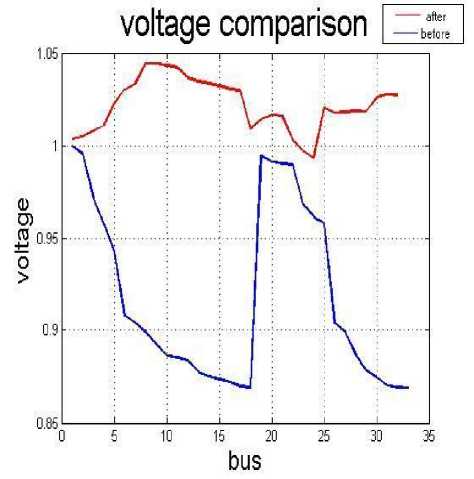
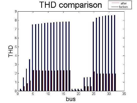
In table 8 and Fig.3 and 4 the results of two cases (before installation and after installation) are compared. As observed in table 8, after optimization by proposed method, power loss was decreased by 39.61% and maximum THD was decreased by 72.74%. Table 8: comparison results
RESULTS
Before installation
After installation
P (kԝ)
578
349
THD (%)
8.55
2.33
V (pu)
1
1.04
V (pu)
0.86
0.99
Fig. 3: voltage comparison Fig. 4: THD comparison VI. Conclusion: In this paper a modified version of pso algorithm (DPSO) which is suitable for discrete problems is applied for optimal placing and sizing of capacitor and DG in distribution system. In some works in spite of taking harmonic into account like [17] resonance occurs at some frequencies, in this work inclusion of resonance index in the objective function prevents occurring resonance. Simulation was done on the modified 33-bus IEEE test system and results are printed. The results show a significant reduction of power losses and THD and improvement of voltage profile in the system after optimal placement and sizing of capacitor and DG by proposed method.
References Optimal Placement and Sizing of Capacitor and Distributed Generation with Harmonic and Resonance Considerations Using Discrete Particle Swarm Optimization
- M.Wang,J.Zhong," a novel method for distributed generation and capacitor optimal placement considering voltage profile",IEEE,2011.
- K.Hghdar,H.A.Shayanfar," optimal placement and sizing of DG and capacitor for the loss reduction via methods of generalized pattern search and genetic algorithm",IEEE.2010.
- A.Mady,I.Tawfeek,"optimal sizing of capacitor banks and distributed generation in distorted distribution networks by genetic algorithms",CIRED,20th international conference on electricity distribution,2009.
- K. Nara, Y. Hayashi, K. Ikeda, T. Ashizawa," Application of tabu search to optimal placement of distributed generators", IEEE PES Winter Meeting, vol. 2, 2001, pp. 918–923.
- H.L. Willis," Analytical methods and rules of thumb for modeling DG distribution interaction",IEEE PES Summer Meeting, vol. 3, Seattle,WA, Jul 2000.
- N. Acharya, P. Mahat, N. Mithulananthan, "An analytical approach for DG allocation in primary distribution network, Int. J. Electr. Power Energy Syst. 2006, PP.669-678.
- K.H. Kim, Y.J. Lee, S.B. Rhee, S.K. Lee, S.-K. You, "Dispersed generator placement using fuzzy-GA in distribution systems", in: IEEE PES Summer Meeting, vol. 3 July, 2002, pp. 1148–1153.
- Y.A. Katsigiannis, P.S. Georgilakis," Optimal sizing of small isolated hybrid power systems using tabu search", Journal of Optoelectronics and Advanced Materials 10 (5) (2008) 1241–1245.
- J.O. Kim, S.W. Nam, S.K. Park, C. Singh, "Dispersed generation planning using improved Hereford Ranch algorithm", Electr. Power Syst. 1998.
- J. Kennedy, R. Eberhart, "Particle swarm optimization", IEEE . Conf. Neural Networks, Perth, Australia, November 1995, pp. 1942–1948.
- K.E. Parsopoulos, M.N. Vrahatis," On the computation of all minimizers through particle swarm optimization, IEEE Trans. Evolut. Comput,2004,PP.211-224.
- X. Yu, X. Xiong, Y. Wu," A PSO-based approach to optimal capacitor placement with harmonic distortion consideration", Electr. Power Syst. 2004,227-233.
- R.A. Krohling, L.S. Coelho," Co-evolutionary particle swarm optimization using Gaussian distribution for solving constrained optimization problems" IEEE Trans. Syst,2006,PP. 1407–1416.
- U. Baumgartner, C. Magele, W. Renhart, "Pareto optimality and particle swarm optimization", IEEE Trans. 2004,PP.1172–1175.
- 'Modeling and Simulation of the Propagation of Harmonics in Electric Power Network Part I: Concepts, Models and Simulation Techniques,” Task Force on Harmonics Modeling and Simulation, IEEE Trans. on PWRD, Vol. 11, No. 1, Jan. 1996 pp. 452-465.
- 'Modeling and Simulation of the Propagation of Harmonics in Electric Power Network Part II: Sample Systems and Examples Task Force on Harmonics Modeling and Simulation", IEEE Trans on Power Delivery, Vol. 11, No. 1, pp. 466-474, Jan. 1996.
- S.A.taher,S.A.Hosseni,"a novel technique for optimal capacitor placement and sizing in distribution systems with non-linear loads based on harmonic source identification",IUST,2008,pp.99-106.
- D. Singh, D., K.S. Verma, "Multiobjective optimization for DG planning with loadmodels", IEEE Transactions on Power Systems 2009,pp. 427–436.
- L.F. Ochoa, A. Padilha-Feltrin, G.P. Harrison, "Evaluating distributed generation impacts with a multiobjective index", IEEE Transactions on Power Delivery 2006,pp.1452-1458.
- J. Kennedy and R. C. Eberhart, “A Discrete Binary Version of the Particle Swarm Algorithm Proc. of the conference on Systems, Man,1997, pp.4104-4109.
- S.K. Goswami, S.K. Basu, A new algorithm for the reconfiguration of distribution feeders for loss minimization, IEEE Trans,1992,1484-1491.
- Abou-Ghazala,A.,"optimal capacitor placement in Distribution Systems Feeding non linear loads", IEEE Bolgona Power Teach conference,2003.
