Optimal Spectrum Access for Users in Multi-Channel Cognitive Radio Networks

Author: Vivek Agrawal, Utkarsh Tiwari, Vishal Agarwal, Palaniandavar Venkateswaran
Journal: International Journal of Wireless and Microwave Technologies(IJWMT) @ijwmt
Article in issue: 1 Vol.3, 2013.
Free access
Cognitive Radio, a software defined radio, is an emerging technology which uses opportunistic spectrum access (OSA) for the efficient utilization of the spectrum. Its main aim is to utilize the unused portions of the spectrum by allowing unlicensed users (secondary users) to transmit data in absence of primary users. In this paper the assignment of multiple primary and secondary users in a multiple channel system is addressed with the sole aim of optimizing the total throughput. We have considered an optimal spectrum access (OSA) algorithm for the allotment of both the primary and secondary users in a multiple channel system and compared the results with the well-known meta-heuristic techniques such as Simulated Annealing (SA) and Tabu Search (TS). The results reveal that OSA algorithm is more efficient as compared to SA and TS as far as throughput optimization is considered.
Opportunistic Spectrum Access, Cognitive radio, Throughput, Simulated Annealing and Tabu Search
Short address: https://sciup.org/15012848
IDR: 15012848
Text of the scientific article Optimal Spectrum Access for Users in Multi-Channel Cognitive Radio Networks
The frequency spectrum is a highly valuable resource for wireless communication but the problem is that most of it has already been assigned to the existing technologies. Federal Communications Commission (FCC) has allocated fixed frequency bands to the existing technologies in order to avoid any interference between them. As a result there is a scarcity of frequency spectrum. The limitation of bandwidth is a serious problem from communication point of view and a solution must be found out so that new technologies can avail the spectrum in future. Although most of the spectrum is in use, a survey conducted by FCC [1, 2] indicates that most of the frequency spectrum is sparsely used in time, space and frequency. Since the spectrum is underutilized, there exists “spectrum holes’’ in the radio spectrum which can be used by the unlicensed users in order to use the frequency spectrum efficiently.
* Corresponding author.
There are generally two kinds of users in any Cognitive radio System: Primary users and Secondary users.
The primary users are the licensed users which are authorised by government bodies to use a particular channel. The Secondary users on the other hand, are unlicensed users who can use the channel in the absence of primary users. The aim of Cognitive radio is to maximise the system throughput through efficient use of the spectrum but at the same time ensuring that the unlicensed users do not cause interference to the licensed users. Throughput is the defined as the total amount of data transmitted per unit time. For the better use of frequency spectrum, FCC has proposed a concept of spectrum pooling [1, 2] in which secondary users borrow spectrum from primary users. This concept is called “Opportunistic Spectrum Access” (OSA). But since the primary users are licensed so the secondary users must stop using the spectrum as soon as the primary users want to use the spectrum. In this regard the Secondary users must be sufficiently agile so as to avoid any interference with the licensed users. Cognitive radio employing flexible and adaptive techniques use Opportunistic Spectrum Access for improving spectrum usage.
An opportunity in frequency indicates that not all of the frequency bands are simultaneously used for transmission at any particular time. Also a particular frequency band is not utilized continuously in time. For instance a particular band may be fully utilized during the day time when the data traffic is high but underutilized for most of the remaining time. So it can be used by unlicensed users for data transmission when it is underutilized. There is also an opportunity based on geographic location. A particular frequency band at any particular instant may be used for transmission by licensed users at a particular place. But the same frequency band at the same time may be empty at a different location.
Thus, for Cognitive Radio networks employing “Opportunistic Spectrum Access”, it is very important to find opportunities in frequency, time or space. Such networks are always in search of spectrum holes for the efficient utilization of the spectrum.
In [3] Hungarian and Greedy algorithms have been considered for the opportunistic spectrum access of Secondary users. The main objective of [3] is to investigate how SUs maximize throughput in a multi-user multi-channel system under different traffic conditions. The proposed algorithms are closer to the optimal solutions with almost no communication overhead. In [4] a fuzzy logic based system is considered for the spectrum access by secondary users. The descriptive factors for choosing the proper secondary unlicensed user are distance of secondary user from primary user, the speed of the secondary user and the total unutilized spectrum.
In this paper we address the problem of OSA solely from the point of view of increasing the throughput of a multi-channel, multi-primary user and a multi-secondary user system. Secondary users (SUs) use the channel only when the primary users (PUs) are absent because the PUs are the licenced users of these bands and thus have higher priority over SUs. We have developed a heuristic through which it is decided that which PU or SU should use which channel if the overall throughput of the system is to be maximized. This heuristic is compared with the traditional and well known search techniques Simulated Annealing (SA) and Tabu Search (TS) and is found to yield better results.
The paper is organised into sections. Following the Introduction (Section I), the System Model is explained in Section II. Section III deals with Simulated Annealing technique and Section IV deals with Tabu Search technique. Section V deals with the proposed Optimal Spectrum Access technique. Section VI gives the results and Section VII concludes the paper.
-
2. System Model
Each channel has a Data Transmission Rate (DTR) associated with it which is the maximum Data Rate that can be offered by that channel. Each User (PU or SU) also has a DTR associated with it which is the Data Rate at which that User wants to transmit data. We take the following assumptions:
-
A. We have assumed a system in which only one PU or one SU can use a channel at a time.
-
B. The PU may use the channel for any number of consecutive time-slots i.e. the PU may use the channel for n*t time where n is an integer and t is the duration of the time-slot.
-
C. Each SU uses the channel for only one time-slot at a time so that the probability of collision with PUs is zero. If needed it senses again at the beginning of the next time slot and then starts transmission again.
-
D. The PUs are not required to change their existing transmission strategies and algorithms to coordinate with SUs.
-
E. We assume that SUs perform perfect sensing, i.e., the false alarm and missing probability of the sensing is zero. Additionally, we assume that the sensing of the channel takes an infinitely small amount of time to finish
2.1. Problem Formulation
We have developed a scheme which acts as an agent which guides the PUs and SUs with varying Data Rate requirements into channels with varying Data Rates in such a manner that the overall throughput of the system is maximized. At the beginning of every time slot, first we search the best possible allocation (i.e. which PU goes into which channel) in terms of total throughput based on the DTR of the arriving PUs and the DTR of the channels available at that point of time and then allocate the PUs into the channels. After this procedure is over for a given time slot, the SU allocation is done in a similar way based on DTR of the arriving SUs and the DTR of the channels available after the PU allocation at that time instant.
We consider a system where at some time instant there are K homogeneous channels or primary bands, I primary users (PUs) and J secondary users (SUs) as follows:
P1, P2, P3 ….PI be the I Primary Users and their DTR be PR1, PR2, PR3….PRI.
S1, S2, S3 ….SJ be the J Secondary Users and their DTR be SR1, SR2, SR3….SRJ
C1, C2, C3 ….CK be the K Channels and their DTR be CR1, CR2, CR3….CRK
We define the following binary variables:
xik = 1 , if P i is allocated the channel C k , 0 otherwise.
yjk = 1 , if S j is allocated the channel C k , 0 otherwise.
Now, the problem can be formu lated as a two Integer Linear Programming Problems (ILP) as follows: Stage I
Maximize Tp = ∑ ∑ xikMin ( CRk , PRi ) (1)
ki
Subject to,
∑ x ik = 1 i ∈ I
∀ k ∈ K
∑ xik = 1 ∀ i ∈ I (3)
k ∈ K
Stage II
Maximize Ts = ∑ ∑ y jk Min ( CRk , SRj )
kj
Subject to, £ yk = 1 vk e K, jeJ
The constraint (2) indicates that no two primary users can be assigned to the same channel and constraint (3) indicates that one primary user cannot be assigned to two channels at the same time. Similar arguments hold for Secondary users in (5) and (6). The constraint (7) indicates that PU and SU cannot use the same channel at the same time instant.
In stage 1 we will find xik and Tp. In stage 2 we use xik found in stage 1 and finally find Ts
Therefore Throughput of the system is equal to
Throughput = Tp + Ts
For large values of I, J and K the solution of the above ILP formulation will take exponential amount of time. So we intend to solve the problem using heuristic techniques.
We define the assignment of PU and channel by the following matrix (PU state) where each row i denotes the ith PU and each column k denotes the kth channel. Then the element in the (i,k)th cell is 1 if Pi is assigned to Ck. The state representation of PU state for the assignment of PU is shown in Fig.1a. Similarly the state representation of SU state for the assignment of SU and the channel is shown in Fig.1b.
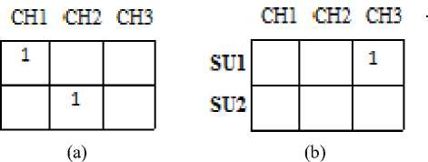
Fig 1.(a) PU State Representation ; ( b) SU State Representation
A state may be defined as one of the many possible permutations of allocating users to channels. A solution state is a feasible state where the constraints (2) (3) for PU states and (5) (6) (7) for feasible SU states. All the three search techniques require searching the neighbour solutions of a given solution in order to find the ultimate optimum solution which maximizes the throughput of the multi-primary, multi-secondary user cognitive radio network.
Let us consider an example-
Let there be 3 channels, C1, C2 and C3 with CR1=6, CR2=2 and CR3=7.
Let there are 2 PUs, PU1 and PU2 arriving at t=t0 (arriving at t=t0 implies that they have arrived between t=t0-1 to t0 and will be serviced at t=t0) with PR1=8, PR2=4
Let there be 2 SUs, SU1 and SU2 also arriving at t=t0 (arriving at t=t0 implies that they have arrived between t=t0-1 to t0 and will be serviced at t=t0) with SR1=4, SR2=1
Let the service times be 1 for all users for simplicity.
Feasible PU states are as follows:
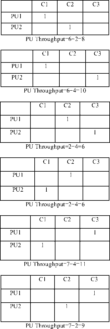
Therefore we see that fifth allocation where x21=1 and x13=1 is the best in which PU1 uses C1 and PU2 uses C3. Therefore Tp=11.
Now that the channels C1 and C3 are busy, only channel C2 is available for SUs. Therefore the possible solutions for SU allotment are as follows:
|
C1 |
C2 |
C3 |
|
|
SU1 |
1 |
||
|
SU2 |
SU Throughput=2
|
C1 |
C2 |
C3 |
|
|
SU1 |
|||
|
SU2 |
1 |
SU Throughput=1
Therefore we see that the first allocation where x12=1 is the best in which SU2 uses C2. Therefore Ts=2. Total Throughput (Tp + Ts) = 10+2=12
-
3. Simulated Annealing (SA)
-
3.1. Neighbour Definition and Generation
Various combinatorial optimization problems can be solved using Simulated Annealing (SA) [5]. SA is a global optimization algorithm which has been used in this paper in the context of throughput maximization. The name annealing is used because this technique is analogous to the metallurgical annealing process. In this technique a neighbour state is randomly selected and replaces the current state based on a probability namely, Acceptance Probability. The Acceptance Probability is dependent on the cost of the initial state, the randomly selected neighbour and the temperature of the system. The algorithm we have used here is not a pure SA algorithm. Pure SA algorithms do not keep track of the best solution found so far in each iteration. Thus a pure SA algorithm at the end of the iterations returns the current state at the last iteration to be the solution, while the modified algorithm that we used returns the best result of all the states visited during the iterations. In most cases this modified SA can be an improvement over the pure SA. In our implementation, the overall throughput of the multiple PU, multiple SU system has to be maximized and for this the modified SA technique has been utilized.
A neighbour is defined as follows:
Case 1: If number of channels is more than or equal to the number of Primary Users or Secondary Users (Fig.2a).
Case 2: If number of channels is less than the number of Primary Users or Secondary Users (Fig.2b).
In this case the neighbours of a state are generated by changing one assignment of the state at a time. Thus generating all permutations which differ from the state S (The state whose neighbourhood is defined) in exactly on assignment 1.In case of case 1 the entity 1 will be restricted to the same column and in case of case2 it is restricted to the same row. The following figure shows the neighbour of the state S.
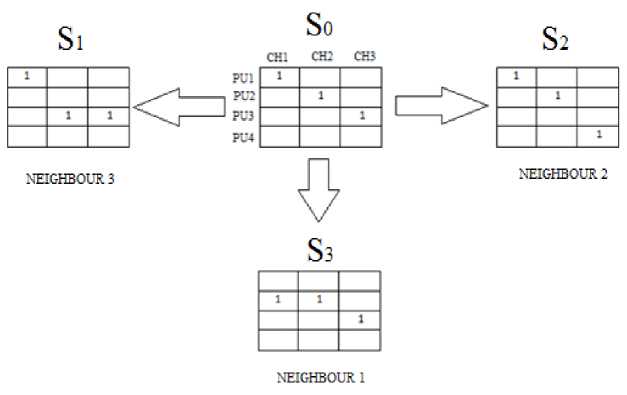
Fig 2.(a) Neighbourhood states of S0 when no. of channels is greater than no. of PUs
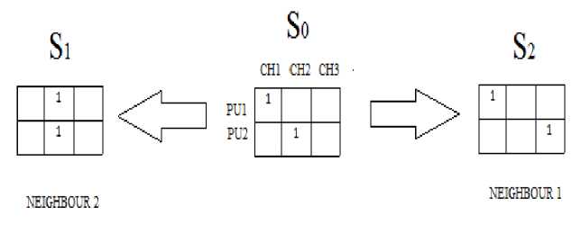
Fig 2. (b) Neighbourhood states of S0 when no. of PUs is greater than no. of channels
Neighbourhood generation of the feasible states are shown in Fig 3. All children of a state may not be feasible. In case one channel is allocated to two users, or one user is allocated two channels, the state is not feasible. Several non-feasible states have been shown in Fig. 3. Only feasible children of a state at the next level without repetitions are its neighbour. In the example shown in Fig. 3, S2 is a child (neighbour) of the current state S1. S1is a child (neighbour) of the state S2 and so on. Neighbours of a node are generated by changing one allocation of the node at a time as shown in the previous section, thus generating all permutations which differ from the parent node in exactly one allocation. In the shown example, S2 differs from its parent in the fact that PU2 is allocated to a different channel, S5 differs from its parent in the fact that PU1 is allocated to a different channel and so on. Hence all pairs of nodes that differ from each other in exactly one allocation are neighbours of each other.
In SA, we start with an initial solution which is made the current node. Then at every iteration, the child node with the maximum throughput is selected as neighbour. If the acceptance probability of the selected node is greater than some threshold, the selected node is accepted for further exploration and is made the current node. If the selected node is not accepted, the child with the 2nd highest throughput is selected as neighbour and so on. In this way the search continues.
-
3.2. Reachability of Neighbourhood Function
-
3.3. Selection Criteria for SA
-
3.4. Annealing Schedule
An exhaustive neighbourhood function is being used so that the search tree thus generated contains all the possible combinations of PU-to-Channel assignments if the algorithm is allowed to generate neighbours for a sufficiently large number of iterations. Hence every node can be reached from every other node and the reachability criterion is satisfied.
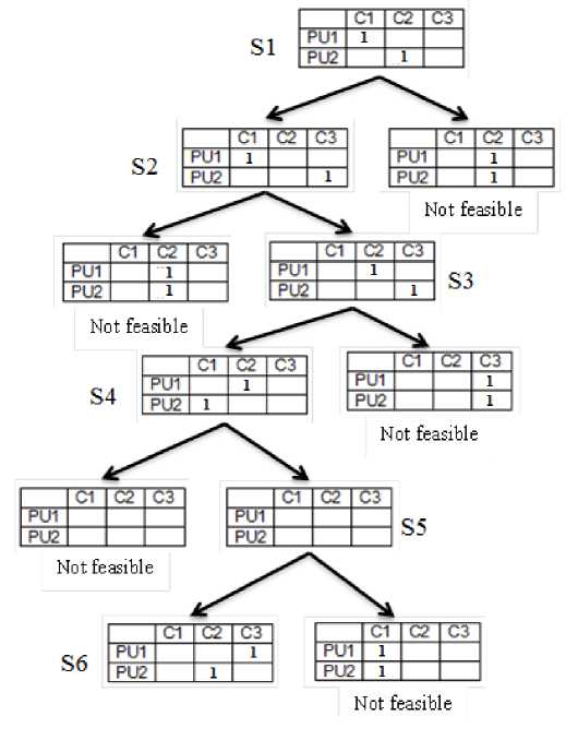
Fig 3: Neighbourhood nodes (states) of a node in the case of PU throughput optimisation
If the throughput th’ of the randomly chosen neighbour S’ of current state S is more than the throughput th of current state S, then the neighbour is selected as the current state for the next iteration. Otherwise, a random number Ran(0,1) between 0 and 1 is chosen from a uniform distribution. If P(S,S´,T) > Ran(0,1) the neighbour is selected as the next current state. Otherwise, the present current state is propagated to the next iteration as the new state. P(S, S´,T) is the acceptance probability and is defined by the Boltzmann probability factor as follows:
P(S, S´, T) = 1, if th < th’
= exp (-ΔC/T) where ΔC = th-th’ otherwise
Typically, update of the temperate T is done by using the relation T = T * α after every M iterations, starting with the initial temperature T = T 0 .
-
3.5. Parameters for Simulated Annealing
The various parameters for the SA algorithm are:
-
• α , the cooling rate i.e. the rate at which the temperature decreases (0 < α < 1)
-
• T , the initial temperature
-
• M, the maximum number of candidate solutions that can be evaluated at a particular temperature
-
• γ, the maximum number of consecutive acceptance of worse solutions
-
• I, the maximum number of iterations
-
3.6. Initial feasible solution
To generate an initial feasible solution, we take the following simple approach. We allocate P1 to C1, P2 to C2 and so on. Sometimes the number of PUs may be lesser than the number of channels available; even then this process is used until highest number PU is assigned to its channel. Rest of the channels are kept empty and the above described Neighbour generating algorithm is followed to generate the subsequent neighbours and cover the entire state space.
Algorithm to Generate Initial Solution:
j=1;
i=1;
if (Max_no_Channels > Max_no_of_Us)
for i=1 to MAX_NO_OF_PUs allocate i to j ;
j=j+1;
end for else for j=1 to Max_no_Channels allocate i to j ;
i=i+1;
end for end else
Then the main SA algorithm sets about imp roving this initial solution. A similar procedure is carried out for SUs also.
The SA procedure is first performed to allocate the PUs into the channels available at that time instant and then the entire procedure is performed for the SUs to allocate them into the remaining channels in such a manner that the overall throughput of the system is maximized and the throughputs are calculated using (1), (4) and (8).
Algorithm using Simulated Annealing:
s ← s0; t ← T(s)
% Initial state, throughput.
smax ← s; tmax ←t
% Initial "best" solution.
iter ← 0
% Throughput evaluation counter.
while iter % While time left. snew ← max_neighbour(s), tnew ← (snew) % Pick neighbour with maximum throughput. if tnew > tmax then % Is this a new maximum? smax ← snew; tmax ← tnew % Save 'new neighbour' to 'Maximum throughput found'. s ← snew; t ← tnew % Yes, change state. else snew ← random_neighbour(s) % Pick random neighbour . tnew ← T(snew) % Compute its Throughput. if P(t, tnew, temp) > random() then % Should we move to it? temp being temperature. s ← snew; t ← tnew % Yes, change state. end if, else iter ← iter + 1 % One more evaluation done. end while return smax,tmax % Return the solution with maximum throughput found . 4. Tabu Search (TS) This process is similar to SA [5]. Here we use a tabu list which stores all solution states that have already been visited. If a newly generated neighbour can be found in this list, it is not accepted otherwise accepted. The list cannot grow infinitely but has a finite maximum length N. Algorithm using Tabu Search: s ← s0; t ← T(s); TL[] ← zeros % Initial state, throughput, Tabu list. smax ← s; tmax ← t % Initial "best" solution. iter ← 0 % Throughput evaluation counters. while iter < i_max % while time left. snew ← max_neighbour(s), tnew ← T(snew) % Pick neighbour with maximum throughput. if snew != TL[i] for all ‘i’then % Check whether snew is already in TL TL[] ← snew % Move this state to TL. s ← snew; t ← tnew % Yes, change state. else snew ← next_best_neighbour(s) tnew ← T(snew) % Pick next best neighbour not in TL. TL[] ← snew % Move this state to TL. s ← snew; t ← tnew % Yes, change state. end else iter ← iter + 1 % One more evaluation done. end while return max_TL[] % Return the solution with maximum throughput found in TL[]. 4.1. Neighbourhood function 4.2. Parameters for Tabu Search The neighbourhood generation used here is similar to Simulated Annealing (Fig.1). Like in SA, all neighbours of the current node are generated. Then the best child (neighbour) not already in the tabu list is selected as the current node and search continues in the same manner. In our implementation, the throughput has to be optimised. Let th and th’ be the throughput of initial state and the best child (neighbour) not already in the tabu list, respectively. Case 1: If th’>th- If the solution corresponding to th’ is present in the tabu list it is ignored and a new neighbour is searched. Otherwise it is put in the Tabu list and made the present state. Case 2: If th’≤th-It is ignored. This process is carried out until the required numbers of iterations are over. The various parameters for the TS algorithm are: • N, the length of the tabu list i.e. how many recent solutions are to be remembered • I, the maximum number of iterations 4.3. Initial feasible solution 5. Optimal Spectrum Access (OSA) Algorithm 5.1. State space creation Same approach is used as in case of Simulated Annealing. The TS procedure is first performed to allocate the PUs into the channels available at that time instant and then the entire procedure is performed for the SUs to allocate them into the remaining channels in such a manner that the overall throughput of the system is maximized and the throughputs are calculated using (1), (4) and (8). This is an Exhaustive search technique which searches all the possible feasible states to find the best solution possible. However, since this technique searches absolutely every possible state, the time taken to solve a large problem will be exponential. The state space in our case is an open tree of state matrices. The s(i, j) is an element of the state S where s(i,j) assumes a value 0 when PUi is not occupying the channel Cj and 1 when the PUi is occupying the channel Cj. Creation of State Space starts with a I*K root matrix S0 where I is the number of PUs and K is the number of channels. . The root state provides information about the channels which are already busy in transmitting data and will remain busy for at least the present time slot. Assuming the channels to be empty initially, the matrix S0 is taken to be NULL matrix. The root state S0 of the state space can be represented as shown below: C1 C2 ……… CK PU1 ::::::: PU2 ::::::: ::::::: PUI …….. This is the only state at level 0 which is the root matrix of the tree. Matrices at the next level are generated by assigning one of the channels to one of the PUs. The corresponding element of the state is set to ‘1’. So, there will be K*I number of matrices at level 1 as shown below: C1 'C2 ……… CK PU1 1 ::::::: PU2 ::::::: ::::::: PUI …….. C1 C2 ……… CK PU1 1 ::::::: PU2 ::::::: ::::::: PUI …….. C1 C2 ……… CK PU1 ::::::: PU2 ::::::: ::::::: PUI …….. 1 From each of the matrices at level 1 child states are generated by placing another ‘1’ in one of the remaining (I*K-1) places thus generating (I*K-1) child States corresponding to each state at level1. Therefore a total of [I*K*(I*K-1)] states will be there at level2. The tree is explored in the similar manner until either all the channels are allotted to the users (when I>=K) or each of the users is assigned a channel (when I<=K). Thus depth of the tree is defined as the level up to which the tree is explored. Mathematically it is given by: Depth=Min (I, K) The complete state space contains [1 + I *K{1 + ( Z )П (I * K - j)}] states ifI and K are >1 and i=1 j=1 (1 + I * K) otherwise. 5.2. Tree traversal and throughput calculation 6. Results and Discussion Depending on the constraints equation 2 and 3, states up to level1 are all feasible. But after that, equation 2 or 3 may not be satisfied thus making it a non-feasible state. The whole tree is traversed in Depth First Search (DFS) manner. The throughput value for root state S0 is assumed to be zero. The throughputs of all other feasible states are calculated using equation (1) show earlier. A variable State ‘S_MAX’ is defined which keeps record of the State which is currently giving the maximum throughput among the throughputs of all the previously generated matrices and ‘MAX_TH’ is the throughput of the corresponding state. Thus initially S_MAX=S0 and MAX_TH=Throughput of S0 If a state is feasible, its throughput is calculated using equation (1) and compared with MAX_TH. If it is more than MAX_TH then existing S_MAX is replaced by this state and MAX_TH is replaced with the throughput of this state. When a state is visited, it is marked as visited so that its throughout is not calculated again. When a non-feasible state is struck, the traversal flow is backtracked to the parent of this state and next child of this parent is visited. If all the child states of a state are visited then flow is again backtracked to the parent of this state. In this manner the whole tree is traversed and at the end the flow reaches back to the root node S0 where it is seen that all of its child states are visited. From this it can be easily concluded that all the states in the tree have been visited, thus making OSA an exhaustive search algorithm. In this way, ever possible allotment is checked and that state is chosen for allotment which on calculation gives the maximum throughput. A similar process is carried out for the Secondary Users and the throughput is calculated using (4). Ultimately the total throughput is calculated using (8). Thus, an optimal solution for allotment is obtained using OSA. We have defined an instance of spectrum access problem by taking the no of PUs, no of SUs, no of channels and the corresponding DTRs. No of channels are varied from 1 to 10. No of PUs at a particular instant are generated from Poisson distribution where the mean arrival rate is taken as 3. Similarly the no of SUs are also generated from Poisson distribution with parameter 2. Algorithm using Optimal Spectrum Access: s← v; t ← T(s) %v is the vertex from where search starts; t is throughput stackst :={ } % start with empty stack for each vertex u set visited[u]:=false smax←s; tmax←t % initial best solution pushst,s; % push state s in stack st while(st is not empty )do u:=pop st; % the last state in stack st is popped in u if( not visited[u] ) then % check whether u is visited or notvisited[u]:=true if( feasible[u]:=true ) then % check feasibility tnew←T(u); % calculate throughput of u if(tnew>tmax ) then % check whether new throughput is greater than tmax tmax←tnew; smax←u; % save u in smax endif endif for each unvisited neighbour w of u pushst,w; endif end while return smax,tmax; % Return the solution with maximum throughput The PU, SU and channel rates are taken from uniform distributions ranging from 0 to 5 units per second. The algorithm SA TS and OSA are run for 100 instances and the average solution cost (throughput) is compared in Fig.3. It shows that when the no. of channels increases the throughput also increases. It shows the trend same for SA and TS but with higher throughput values for TS. The throughput for OSA increases with the no. of channels up to a certain extent and then it saturates. This is because the channel capacity is utilized to the maximum extent possible. Fig 4: Variation of throughput vs. Number of channels for different techniques used 7. Conclusions We have formulated the Multi-PU, Mu lti-SU Cognitive Radio networks as a two stage ILP problem and we have solved it using two meta-heuristic techniques SA and TS and one proposed exhaustive enumeration technique, OSA. The proposed OSA technique is based on DFS algorithm. It is observed that SA and TS techniques give solutions closer to the proposed OSA technique. Between the two meta-heuristic techniques it is found that TS gives better solution. For large problems exhaustive enumeration technique will take exponential amount of time where the technique SA and TS will be useful. In this paper we have considered that the SUs transmit for only 1 time slot. Future works in this direction may include the fact that SUs like PUs may transmit for consecutive time-slots. Further, the channel may be considered un-slotted in future works. Conditions with imperfect sensing may also be addressed.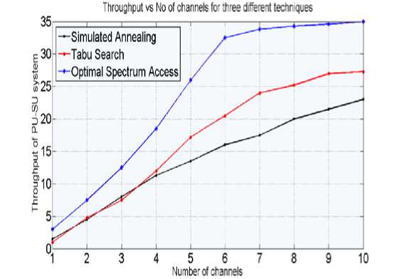
References Optimal Spectrum Access for Users in Multi-Channel Cognitive Radio Networks
- Danijela Cabric, Shridhar Mubaraq Mishra, Robert W. Brodersen “Implementation Issues in Spectrum Sensing for Cognitive Radios”, Asilomar Conference on Signals, Systems, and Computers, 2004.
- Simon Haykin “Cognitive Radio: Brain-Empowered Wireless Communications”, IEEE JOURNAL selected on areas in communications, Volume: 23, No. 2, February, 2005.
- Senhua Huang Xin Liu, Zhi Ding “Opportunistic Spectrum Access in Cognitive Radio Networks”, IEEE INFOCOM 2008 Proceedings, Volume: 24, Issue: 3, Publisher: IEEE, Pages: 79-89.
- Partha Pratim Bhattacharya “A Novel Opportunistic Spectrum Access for Applications in Cognitive Radio”: Ubiquitous Computing and Communication Journal Volume 4 No 2 Page 24 Website: www.ubicc.org.
- Samir K Sadhukhan, Swarup Mondal, Saroj R Biswas, Partha Bhaumik, Debashish Saha“ Post-deployment Tuning of UMTS Cellular Networks through Dual-homing of RNCs” Submitted to IEEE COMSNET 2009.
