Oscillation suppression of pedestrian overpasses

Author: Shmelev Gennady Nikolaevich, Eremeev Daniil Valerievich, Eremeev Valery Pavlovich, Eremeev Pavel Valerievich
Journal: Строительство уникальных зданий и сооружений @unistroy
Article in issue: 5 (103), 2022.
Free access
The objects of research are pedestrian overpasses. The purpose of this work is to analyze the issues of suppression of such overpasses from oscillation caused by movement of trains and crowds. There are many ways to suppress oscillation, including increasing the longitudinal stiffness, introducing an additional connection, and using elastic or viscoelastic dampers. Problems arise when determining the need for measures to suppress oscillation in particular cases. Method. The need for suppression is determined for a pedestrian overpass with a span of 44.6 m, which is tested to determine the natural vibration frequency and the logarithmic decrement of attenuation. A comparative analysis of different solutions for oscillation suppression is carried out. A computational model of a pedestrian overpass based on the finite element method is developed. The dynamic impact from the crowd is set as a time - force function, based on the condition that 12.5% of pedestrians move synchronously. The possibility of simplifying the design scheme by replacing the base and supports with boundary conditions is determined. The dynamic influence of a train on a pedestrian overpass is studied. The load from the train is set by the time-force function and the displacement equation. Three different cases of loading from the train are studied, varying on weight and the number of wheels. Results. A comparative analysis of oscillation damping measures shows that the most effective solution is to introduce a viscoelastic damper. This way, it is possible to reduce the mean square acceleration of oscillations by 8.4 times to the required values, with the lowest material consumption.
Pedestrian overpasses, dynamics, oscillation, suppression, dampers, construction
Short address: https://sciup.org/143179858
IDR: 143179858 | UDC: 69 | DOI: 10.4123/CUBS.103.1
Text of the scientific article Oscillation suppression of pedestrian overpasses
The use of new polymer and composite materials allows increasing the length of pedestrian overpasses, which, in turn, increases their flexibility and natural period of oscillation [1]–[4]. This creates risks of resonant oscillations from the influence of groups of people [5]–[7]. Issues of ensuring dynamic safety are actively investigated, including measures to dampen oscillations [8]–[11].
The dynamic state of pedestrian overpasses is usually determined by two criteria – the natural period of oscillation of structures, the restriction of which makes it possible to avoid resonant phenomena, and the acceleration of vibrations of the structure under dynamic influence, the restriction of which ensures the comfort of the pedestrian [12].
According to the international standards ISO 10137:2007 (E), the limit value of the oscillation rate is determined by the basis curve (Fig. 1), multiplying the value obtained from this graph by a multiplier equal to 60 for pedestrian crossings.
The authors of the article "Synchronization of human walking observed during lateral vibration of a congested pedestrian bridge" analyze video materials and determine that about 20 % of pedestrians move in sync with the vibrations of the bridge, at a frequency of 0.9 Hz and an amplitude of 10 mm [13].
In the article "Modeling crowd-bridge dynamic interaction with a discreetly defined crowd", the authors present a new method for crowd modeling using the theory of discrete elements. Pedestrians are modeled as separate elements that share common properties [14].
In the study "Pedestrian-bridge dynamic interaction, including human participation", the pedestrian is modeled taking into account the flexibility of the legs, so, the person is replaced by a nonlinear damper moving at a given speed [15].
The criterion of the natural period of oscillation does not allow us to take into account the influence of a viscoelastic damper [16], so it becomes necessary to evaluate the design by the standard acceleration criterion [17]–[19].
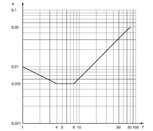
Fig. 1 - Graph of the dependence of the mean-square acceleration a (m/s2) on the frequency in Hz
Questions arise when setting the driving load in the calculation scheme from a group of people [20]. Although in most models the load from a pedestrian is considered as an external force, the movement of the structure can actually affect human behavior, thereby changing the forces of dynamic interaction [21]–[24].
There are many studies devoted to finding the optimal solution for setting the load from the group, taking into account its dynamic influence [25]–[27].
Scientists also explore the load from people, including walking, running, jumping, and dancing. As a result, they receive graphs of human loads for walking at different frequencies. At the same time, the vertical dynamic component of walking at a frequency of 2 Hz reaches 37 %. These pieces of data are obtained for stationary sidewalks, but the authors note that during walking on structures that have significant displacements, the phenomenon of unconscious synchronization may occur, when a person walking on a vibrating structure adjusts the frequency of his walk to the vibrations [28]–[30]. This phenomenon is most pronounced with larger amplitude of vibrations, about 10-20 mm. Synchronization is typical for both vertical and lateral horizontal oscillations.
-
2 Materials and Methods
The issues of oscillation damping are considered on the example of a pedestrian overpass with a span of 44.6 m. In the course of dynamic tests, significant vibrations are detected during swinging, accompanied by the sound of cracking of the glazing. The period of natural oscillation of the transition is 0.42 s, which is close to the unacceptable range of 0.45 - 0.6 s. However, it should be taken into account that according to the normative documents, the tests should be carried out in an unloaded state, because additional masses increase the period of natural oscillations. Also, this transition has a relatively high flexibility, which creates risks of the phenomenon of unconscious synchronization. Thus, seemingly harmless vibrations can develop into resonant ones, which is unacceptable.
The creation of a finite element model and modeling of dynamic forcing loads are carried out in the software complexes Midas GTS NX and Midas Civil. The model represents the computational Eremeev, P.; Eremeev, V.; Eremeev, D.; Shmelev, G.
Oscillation Suppression of Pedestrian Overpasses;
2022; Construction of Unique Buildings and Structures; 103 Article No 10301. 10.4123/CUBS.103.1
domain with dimensions 100 × 200 m and includes bases, piles of foundation, reinforced concrete posts, crossbars and span structure of the pedestrian overpass. Three-dimensional elements are modeled using tetrahedral finite elements.
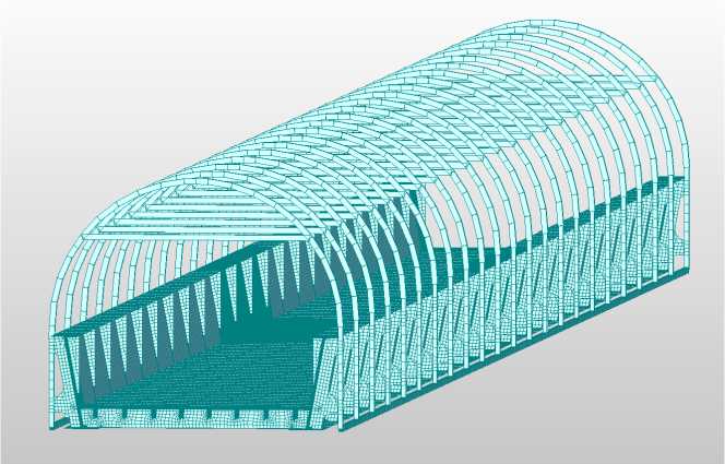
Fig. 2 - Design scheme of the overpass (span of 44.6 m)
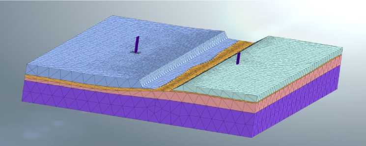
Fig. 3 - Design scheme including soil, foundation, and bearing supports
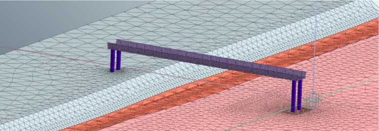
Fig. 4 - Design scheme including soil, foundation, bearing supports and span structure
When developing solutions for vibration damping, the terrain features are taken into account, namely the presence of railway tracks under the span structure. The question of setting the dynamic load from the train is poorly studied, so a number of assumptions are made:
-
1) Riding surfaces of the wheels and rails are assumed to be perfectly smooth;
-
2) Rails along their length are assumed to be of constant stiffness, despite their discreteness, since it is difficult to determine the vibrations caused by changes in the elastic force;
-
3) Wheels of the rails do not have such defects as potholes, ovality, imbalance and eccentricity; there are no breaks in the rail tracks that can cause an impact;
-
4) Rail track material is constant in its length properties;
Eremeev, P.; Eremeev, V.; Eremeev, D.; Shmelev, G.
Oscillation Suppression of Pedestrian Overpasses;
2022; Construction of Unique Buildings and Structures; 103 Article No 10301. 10.4123/CUBS.103.1
-
5) Train is moving at a constant speed.
Taking into account the above assumptions, it is assumed that vibrations in the ground are caused by quasi-static excitation that is the movement of concentrated forces.
The design scheme is made in accordance with modern regulatory standards.
The load from the train is modeled by the force-time function and the load displacement equation (Fig. 5-7).
As part of this work, 3 types of trains are specified:
-
1) Two diesel locomotives;
-
2) Train with eight wagons;
-
3) Train with twenty wagons.
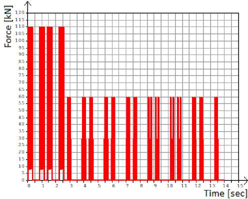
Fig. 5 - Graph of changes in the load on one point of the design scheme from loading with the 1st type of train (two diesel locomotives)
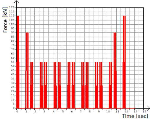
Fig. 6 - Graph of changes in the load on one point of the design scheme from loading with the 2nd type of train (eight wagons)
Damping of the system is also taken into account in the calculation, according to recommendations of the previously introduced article about material damping in the calculation of structures for dynamic effects.
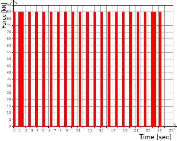
Fig. 7 - Graph of changes in the load on one point of the design scheme from loading with the 3rd type of train (twenty wagons)
Base, foundation, and supports in the design scheme impose significant restrictions on the number of finite elements and integration steps, which is not desirable for dynamic calculations. Therefore, studies have been conducted to determine whether they can be replaced by equivalent boundary conditions.
Two corresponding design schemes are considered. The driving load is assumed to be the load from a crowd of people, as a time-varying static load, according to the graph in figure 8.
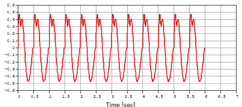
Fig. 8 - Graph of dynamic impact from a crowd of people
Four main methods of oscillation dampening are adopted, taking into account the terrain features:
-
1) Introduction of an additional vertical post,
-
2) Introduction of an elastic damper,
-
3) Introduction of a viscoelastic damper,
-
4) Increasing longitudinal stiffness.
The calculation is performed without taking into account the base, foundation, and supports, since they impose restrictions on the number of finite elements and the integration step.
The following dynamic loadings are accepted:
-
1) Time-varying static load, according to the function in Fig. 8.
-
2) Own weight, necessary for calculation with the participation of dampers for correct display of forces arising in them (Fig. 9).
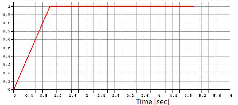
Fig. 9 - Graph of the load from own weight
5.00E-05
4.00E-05
3.00E-05
2.00E-05
3 Results and Discussion
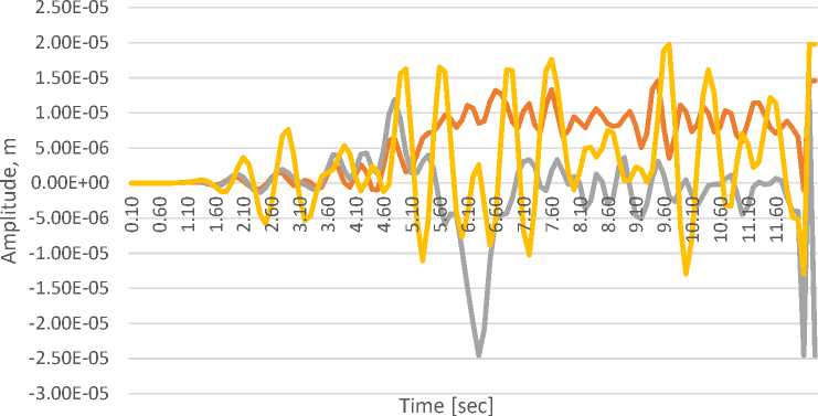
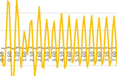
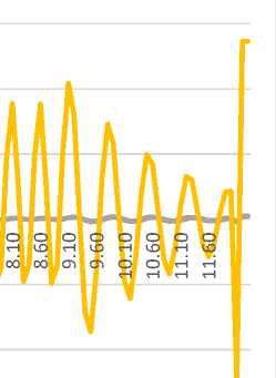
Based on the results of the calculation, diagrams of the mid-span and support zones movements are obtained.
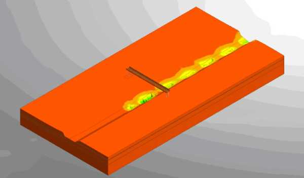
Fig. 10 - Deformations of the design model during train movement
Е 1.00E-05 а? 0.00E+00 тз
5 -1.00E-05
Е -2.00E-05 <
-3.00E-05
-4.00E-05
-5.00E-05
Time [sec]
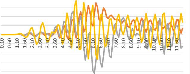
^^^^^^Left support ^^^^^м Right support ^^^^^е Mid-span
Fig. 11 - Diagram of span structure oscillations from loading with the 1st type of train
2.50E-05
-2.00E-05
Time [sec]
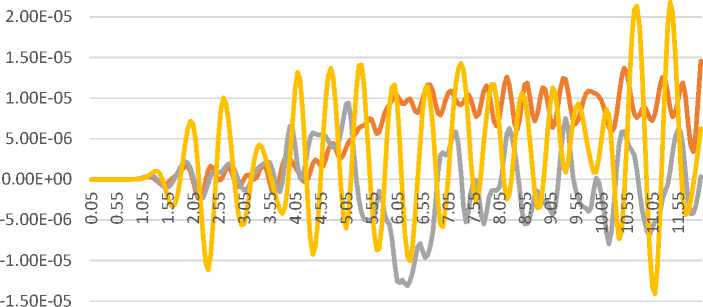
^^^^^^ Left support ^^^^^^ Right support ^^^^^^Mid-span
Fig. 12 - Diagram of span structure oscillations from loading with the 2nd type of train
^^^^^^ Left support ^^^^^^ Right support ^^^^^ Mid-span
Fig. 13 - Diagram of span structure oscillations from loading with the 3rd type of train
6.00E-02
4.00E-02
Е 2.00E-02 а?
В 0.00E+00
Е
< -2.00E-02
-4.00E-02
-6.00E-02
Time [sec]
^^^^^^ Left support ^^^^^^ Right support ^^^^^^Mid-span
Fig. 14 - Diagram of span structure oscillations from combined action of people and train (equal for all train types)
The results of the calculation are diagrams of oscillations in the middle of the span and the support zones, as well as a comparative diagram.
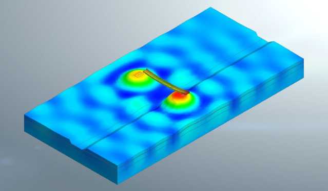
Fig. 15 - Deformations of the design model under the influence of a crowd of people
0.15
0.10
0.05 а?
0.00 "а.
-0.05
-0.10
Time [sec]
-0.15
Left support Right support Mid-span
Fig. 16 - Diagram of the oscillations of the span structure in the design model with base
0.15
-0.15
Time [sec]
Model with foundation Model without foundation
Fig. 17 - Comparative diagram of mid-span oscillations of two design models
The results of the calculation are diagrams of oscillations of displacements and accelerations of the mid-span for each method of oscillation damping as well as the reaction of vertical posts.
The results are shown in the comparison table.
Acceptable mean-square acceleration value for a pedestrian overpass is obtained through the following equation:
[ a ] = 60*0.007 = 0.42^2
s2
The following diagrams (Fig. 18, 19) are obtained for each solution for oscillation damping.
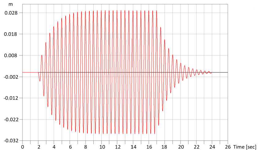
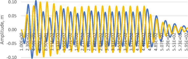
Fig. 18 - Diagram of displacement oscillations in the middle span of a pedestrian overpass
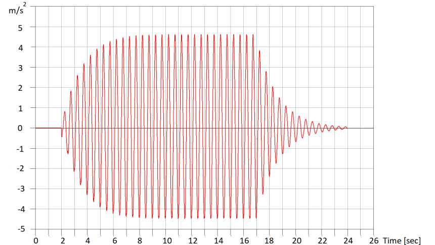
Fig. 19 - Diagram of acceleration oscillations in the middle span of a pedestrian overpass
The logarithmic decrement of oscillation damping is defined by the formula:
Я = ln
А ( t ) А ( t + Т )
Where
А ( t ) - amplitude of the n-th oscillation,
А ( t + Т ) - amplitude of the n + 1 st oscillation.
Table 1. Comparative table of solutions for oscillation damping
|
№ |
State of the design object |
Maximum displacement, mm |
am.sq , s 2 |
Л |
Reaction of the additional vertical post, kN |
Additional metal consumption, kg |
|
1 |
Initial state |
29 |
3.22 |
0.316 |
--- |
--- |
|
2 |
Introduction of an additional vertical post |
0.0016 |
0.000128 |
0.326 |
783 |
327.6 |
|
3 |
Increasing longitudinal stiffness |
0.0108 |
0.94 |
0.318 |
--- |
2321 |
|
4 |
Introduction of the elastic damper |
13.1 |
0.88 |
0.316 |
207.9 |
152.8 |
|
5 |
Introduction of the viscoelastic damper |
3.1 |
0.384 |
2.33 |
64.75 |
51.6 |
-
4 Conclusions
As can be seen from the results, the effect of quasi-static excitation from the train on the span structure of the pedestrian overpass is insignificant. The maximum value of the span structure movements caused by the train is 0.042 mm. From this it can be concluded that in order to determine the dynamic influence of the train, it is necessary to conduct further research and measure the oscillations of the rails.
The results of the calculation to determine the possibility of replacing the base, foundation and supports in the design scheme with equivalent boundary conditions reveals this possibility.
The solution to introduce an additional vertical post allows achieving the lowest acceleration amplitude, but this is achieved by overspending the material, in comparison with other solutions.
Increasing the longitudinal stiffness allows avoiding underground work and does not restrict the space under the span structure, but this solution requires significant material consumption and can lead to the termination of operation of the structure for a relatively long time.
A comparative analysis of oscillation damping measures has shown that the most effective solution is to introduce a viscoelastic damper – it is possible to reduce the mean square acceleration of oscillations by 8.4 times to the required values, with the lowest material consumption out of all other choices.
References Oscillation suppression of pedestrian overpasses
- Bedon, C. Diagnostic analysis and dynamic identification of a glass suspension footbridge via on-site vibration experiments and FE numerical modelling. Composite Structures. 2019. 216. DOI:10.1016/j.compstruct.2019.03.005.
- Chróścielewski, J., Miśkiewicz, M., Pyrzowski, Ł., Rucka, M., Sobczyk, B., Wilde, K. Modal properties identification of a novel sandwich footbridge – Comparison of measured dynamic response and FEA. Composites Part B: Engineering. 2018. 151. DOI:10.1016/j.compositesb.2018.06.016.
- Bedon, C., Bergamo, E. Vibration experiments for diagnostic investigations on a glass suspension footbridge. Vibroengineering Procedia. 2019. 24. DOI:10.21595/vp.2019.20612.
- Qin, S., Zhou, Y.L., Kang, J. Footbridge Serviceability Analysis: From System Identification to Tuned Mass Damper Implementation. KSCE Journal of Civil Engineering. 2019. 23(2). DOI:10.1007/s12205-018-0985-7.
- Wang, D., Wu, C., Zhang, Y., Li, S. Study on vertical vibration control of long-span steel footbridge with tuned mass dampers under pedestrian excitation. Journal of Constructional Steel Research. 2019. 154. DOI:10.1016/j.jcsr.2018.11.021.
- Miguel, L.F.F., Fadel Miguel, L.F., Lopez, R.H. A firefly algorithm for the design of force and placement of friction dampers for control of man-induced vibrations in footbridges. Optimization and Engineering. 2015. 16(3). DOI:10.1007/s11081-014-9269-3.
- Newland, D.E. Pedestrian excitation of bridges. Proceedings of the Institution of Mechanical Engineers, Part C: Journal of Mechanical Engineering Science. 2004. 218(5). DOI:10.1243/095440604323052274.
- Bocian, M., Macdonald, J.H.G., Burn, J.F. Biomechanically Inspired Modeling of Pedestrian-Induced Vertical Self-Excited Forces. Journal of Bridge Engineering. 2013. 18(12). DOI:10.1061/(asce)be.1943-5592.0000490.
- Venuti, F., Racic, V., Corbetta, A. Modelling framework for dynamic interaction between multiple pedestrians and vertical vibrations of footbridges. Journal of Sound and Vibration. 2016. 379. DOI:10.1016/j.jsv.2016.05.047.
- Lai, E., Gentile, C., Mulas, M.G. Experimental and numerical serviceability assessment of a steel suspension footbridge. Journal of Constructional Steel Research. 2017. 132. DOI:10.1016/j.jcsr.2017.01.005.
- Demartino, C., Avossa, A.M., Ricciardelli, F. Deterministic and probabilistic serviceability assessment of footbridge vibrations due to a single walker crossing. Shock and Vibration. 2018. 2018. DOI:10.1155/2018/1917629.
- Tubino, F. Human-structure interaction in pedestrian bridges: A probabilistic approach. Procedia Engineering. 2017. 199. DOI:10.1016/j.proeng.2017.09.584.
- Fujino, Y., Pacheco, B.M., Nakamura, S. ‐I, Warnitchai, P. Synchronization of human walking observed during lateral vibration of a congested pedestrian bridge. Earthquake Engineering & Structural Dynamics. 1993. 22(9). DOI:10.1002/eqe.4290220902.
- Carroll, S.P., Owen, J.S., Hussein, M.F.M. Modelling crowd-bridge dynamic interaction with a discretely defined crowd. Journal of Sound and Vibration. 2012. 331(11). DOI:10.1016/j.jsv.2012.01.025.
- Qin, J.W., Law, S.S., Yang, Q.S., Yang, N. Pedestrian-bridge dynamic interaction, including human participation. Journal of Sound and Vibration. 2013. 332(4). DOI:10.1016/j.jsv.2012.09.021.
- Hu, J., Bian, X., Jiang, J. Critical Velocity of High-speed Train Running on Soft Soil and Induced Dynamic Soil Response. Procedia Engineering. 2016. 143. DOI:10.1016/j.proeng.2016.06.102.
- Ntotsios, E., Koroma, S.G., Hamad, W.I., Thompson, D.J., Hunt, H.E.M., Talbot, J.P., Hussein, M.F.M. Modelling of Train Induced Vibration. Stephenson Conference Research for Railways 2015. 2015. 2015-April.
- Barabash, M.S., Pikul, A. V., Bashynska, O. THE MODELING OF STRUCTURAL ENFORCEMENT BY COMPOSITE MATERIALS ON “LIRA-SAPR.” International Journal for Computational Civil and Structural Engineering. 2017. 13(1). DOI:10.22337/2587-9618-2017-13-1-34-41.
- Ahmadi, E., Caprani, C., Živanović, S., Heidarpour, A. Vertical ground reaction forces on rigid and vibrating surfaces for vibration serviceability assessment of structures. Engineering Structures. 2018. 172. DOI:10.1016/j.engstruct.2018.06.059.
- Lu, P., Zhou, Y., Lu, Q., Wang, J., Shi, Q., Li, D. Conceptual Design of the Pedestrian Bridge. Structural Engineering International. 2021. DOI:10.1080/10168664.2021.1911610.
- Golkar, N., Sadeghpour, A., Divandari, J. Drawing inspiration from the spine, designing a pedestrian bridge [spine-inspired design of a pedestrian bridge]. Journal of Architecture and Urbanism. 2021. 45(2). DOI:10.3846/jau.2021.13369.
- Ali, S., Thambiratnam, D., Liu, X., Fawzia, S. Numerical study of pedestrian suspension bridge with innovative composite deck. Heliyon. 2020. 6(7). DOI:10.1016/j.heliyon.2020.e04473.
- Ali, S., Thambiratnam, D., Liu, X., Fawzia, S. Performance evaluation of innovative composite pedestrian bridge. Structures. 2020. 26. DOI:10.1016/j.istruc.2020.05.010.
- Dey, P., Narasimhan, S., Walbridge, S. Reliability-based assessment and calibration of standards for the lateral vibration of pedestrian bridges. Engineering Structures. 2021. 239. DOI:10.1016/j.engstruct.2021.112271.
- Ali, S., Thambiratnam, D., Fawzia, S., Nguyen, K.D., Van Den Elsen, H., Fujii, I.A. Damage detection of an innovative composite slab-girder pedestrian bridge using vibration characteristics. Structure and Infrastructure Engineering. 2021. DOI:10.1080/15732479.2021.1880447.
- Ali, S., Thambiratnam, D., Fawzia, S., Nguyen, K.D., Leung, F.Y. Structural performance evaluation of innovative composite pedestrian arch bridge. Structure and Infrastructure Engineering. 2021. 17(1). DOI:10.1080/15732479.2020.1730411.
- Štimac Grandić, I. Serviceability verification of pedestrian bridges under pedestrian loading. Tehnicki vjesnik - Technical Gazette. 2015. 22(2). DOI:10.17559/tv-20131030105641.
- Jamadin, A., Ibrahim, Z., Mohd Amin, N., Alisibramulisi, A., Suliman, N.H., Malai Hussin, M.H.S. Dynamic behaviour of existing steel pedestrian bridge. International Journal of Civil Engineering and Technology. 2018. 9(7).
- Bank, L.C., Oliva, M.G., Bae, H.U., Bindrich, B. V. Hybrid concrete and pultruded-plank slabs for highway and pedestrian bridges. Construction and Building Materials. 2010. 24(4). DOI:10.1016/j.conbuildmat.2009.10.002.
- Liu, Q.Z. Scheme Designand Structural Performance of Steel Trussed Arch Pedestrian Bridges. Wuhan Ligong Daxue Xuebao/Journal of Wuhan University of Technology. 2021. 43(3). DOI:10.3963/j.issn.1671-4431.2021.03.006.
