Parametric analysis of the anisogrid body of the spacecraft for cleaning the orbit of space debris

Author: Belonovskaya I. D., Kolga V. V., Yarkov I. S., Yarkova E. A.
Journal: Siberian Aerospace Journal @vestnik-sibsau-en
Section: Aviation and spacecraft engineering
Article in issue: 1 vol.22, 2021.
Free access
The article presents an approach to solving the problem of designing a spacecraft for cleaning the orbit of space debris (space garbage collector-KSM), the body of which is made in the form of a cylindrical mesh anisogrid shell. The design task is to select the optimal parameters of the anisogrid body of the KSM (the shape and cross-sectional area of the ribs, the number of annular and spiral ribs, material characteristics, etc.) that provide the necessary strength and stability of the structure with minimal weight. During the design process, a parametric analysis of the anisogrid housing of the space garbage collector was carried out. By varying the number and angle of inclination of unidirectional spiral ribs, we find the optimal design scheme that satisfies the specified safety and stability coefficients. Parametric analysis of the KSM body includes modeling of the main weight and strength parameters: determination of the stress-strain state of the structure, values of the body’s natural frequencies, determination of the bending margin from the longitudinal force, determination of the body mass. The analysis of the load-bearing capacity of the anisogrid housing of the space garbage collector was carried out by the finite element method using the MSC Nastran software package. A finite element mesh model was created from a two-node spatial finite element bundle. The disk attached to the end of the shell was modeled using a rigid finite element. The size of the final beam element for all shell models was the same and equal to 10 mm. During the parametric analysis, three variants of the mesh composite structure with a different number and angle of inclination of unidirectional spiral ribs were considered. Based on the results of parametric analysis of the spacecraft body, its geometric dimensions are determined and the mass of the spacecraft structure as a whole is minimized.
Spacecraft, parametric analysis, spacecraft strength, space debris collection, vibration frequency, stress-strain state, loss of stability, spacecraft design.
Short address: https://sciup.org/148321790
IDR: 148321790 | UDC: 536.2 | DOI: 10.31772/2712-8970-2021-22-1-94-105
Text of the scientific article Parametric analysis of the anisogrid body of the spacecraft for cleaning the orbit of space debris
Introduction. Since the launch of the first artificial Earth satellite, all states have carried out more than 5000 launches of rocket vehicles. Over the entire period of space exploration, more than 30 thousand large
(larger than 10–20 cm) space objects (SO) were launched into near-earth space. There are much more registered ones (about 35 thousand) due to the fragmentation of some large space objects. More than two-thirds of them still remain in orbits and are monitored by ground-based and space-based observation devices. Today, officially, over 17 thousand SOs have been cataloged [1].
According to statistics, the share of Russia, the United States and China accounts for 93% of garbage objects. The share of other countries in total is about 7% (according to other estimates for 2014 Russia – 39.7%; USA – 28.9%; China – 22.8%, other countries – 8.6%) [1 ].
The orbits most populated by space garbage are those with the highest concentration of objects relative to other areas. These are orbits with an altitude of 250 to 1000 km.
Space garbage means all artificial objects and their fragments in space that are malfunctioning and do not function but are a potentially dangerous factor affecting functioning and launched spacecrafts (SC). In some cases, large or containing hazardous (nuclear, toxic, etc.) materials on board, space garbage objects can pose a direct hazard to the Earth during their uncontrolled deorbiting, incomplete combustion when passing through dense layers of the atmosphere of the Earth and garbage falling onto settlements, industrial facilities, transport communications, etc.
The problem of contamination of near-earth space with “space garbage”, as a purely theoretical one, arose essentially immediately after the launch of the first artificial earth satellites in the late fifties. It received official status at the international level after the report of the UN Secretary General entitled “The impact of space activities on the environment” on December 10, 1993, where it was emphasized that the problem is of an international, global nature [2]. The need for measures to reduce the intensity of man-made garbage in space becomes clear when considering possible scenarios for space exploration in the future. When extrapolating the existing conditions of low Earth orbits (LEO) clogging, the “cascade effect” from mutual collisions of objects and space debris particles can lead to a catastrophic increase in their number on LEO and, as a consequence, to the practical impossibility of further space exploration. It is assumed that after 2055 the process of self-reproduction of the remnants of human space activities will become a critical problem for the further development of world cosmonautics [1; 2].
The trend of development and design of prototypes of space garbage collectors (SGCs) all over the world is becoming more and more relevant due to the increase in the number of spacecraft launches into various orbits. To solve the problems of collecting space garbage (upper stages of the launch vehicle, spent satellites and their fragments), designed spacecraft intended for cleaning orbits, according to the principle of impact on garbage, are divided, as a rule, into two types:
-
1. Contact (capture of garbage by a manipulator, rope, net, harpoon, etc.).
-
2. Non-contact (destruction of debris when exposed to a laser installation, ion flow, electrostatic field and collection of small garbage).
All of these projects have one common drawback: all projects are “one-off”, i.e. limited to one working cycle. It should be borne in mind that the work of any space scavenger requires energy expenditure to change the orbit, docking with garbage, and, therefore, acceleration, deceleration and manoeuvring in orbit. As a rule, the energy of solar cells for such complex movements is insufficient. Therefore, when designing “reusable” SGC, it is necessary to take into account its energy capabilities [3] for the implementation of several working cycles.
In the above study, the task of designing a space garbage collector (SGC) determined the development of a spacecraft capable of providing several operating cycles of space garbage removal from orbit to reduce the cost of 1 kg of space debris removed from orbit. At the same time, the SGC must have a limited mass and dimensions for a more compact placement under the head fairing of the launch vehicle [4–9].
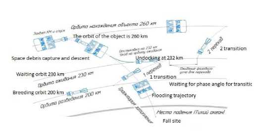
Duty cycle of the space garbage collector. To design a SGC with several working cycles, consider the order of its operation, including the capture and removal from orbit of one piece of space garbage (SG). The working cycle includes the following stages (fig. 1).
Undoc^ag at 232 km
Waiting orbit 230 km 2ЗО
Waitingfor phase angle fortransition f looding trajectory
Земля
Рисунок 1. Рабочий цикл космического сборщика мусора Figure 1. Space garbage collector duty cycle
Рис. 1. Рабочий цикл космического сборщика мусора
-
Fig. 1. Space garbage collector duty cycle
-
1. Launch. Upon reaching the redeployment orbit (payload separation, altitude 200 km), the separation devices are activated, and a spring mechanism pushes it away from the warhead adapter. Control checks and orbit adjustments are underway. At LEO, SGC is awaiting command to enter phasing orbit.
-
2. Hohmann transition. Manoeuvre of transition to the waiting orbit (phasing orbit). The first start of the engine raises the spacecraft to a design altitude of 230 km along an elliptical trajectory. The second pulse is intended for correction and stabilization in a circular phasing orbit (first transition).
-
3. Orbit of waiting (phasing). Height: 230 km. Waiting for the command to enter the space garbage capture orbit. The orbital speed of the spacecraft is 130 km / h higher than that of the garbage in orbit of 260 km. The SGC waits for the required phase angle, after which it leaves for a rendezvous with space garbage.
-
4. Bielliptic transition. To transfer a rocket drone from a waiting orbit (phasing) to a space garbage orbit, the Hohmann transition is not accurate enough. For this, a manoeuvre with three engine start-ups is used - a bielliptic transition (second transition).
-
5. Docking. After the transfer of the space garbage to the garbage capture orbit, it is necessary to ensure its deceleration and guidance of the gripping manipulators to the space garbage fragment (SG) using the correction engines and the onboard radar system. The computer automatically controls the manoeuvring engines and ensures the capture of the object. In the event of a non-standard situation, the onboard system will cancel the docking and return the spacecraft to the phasing orbit to search for a new target.
-
6. Descent. After the manipulators successfully capture the garbage, the spacecraft makes a manoeuvre from orbit to the flooding trajectory. At an altitude of 232 km, the SGC undocks from the garbage, which continues to move along a given trajectory and enters the dense layers of the atmosphere, where it burns up or falls into a predetermined point “Nemo” located in the Pacific Ocean.
The SGC transfers from the flooding trajectory to the phasing orbit and starts a new operating cycle.
According to the calculation data, one SGC removes from 3 to 6 “I” blocks with a mass of 2.7 t (the third stage of the Soyuz LV) with orbits up to 300 km. The number of duty cycles depends on the orbital altitude of the garbage fragment and the required orbital manoeuvres for docking and removal of garbage from orbit.
Design of a space garbage collector.
To ensure several duty cycles of cleaning orbits from space garbage, the following design of a space garbage collector was proposed (fig. 2). At the same time, the requirements of minimizing the mass and dimensions of the spacecraft were taken into account.
Structurally, the SGC consists of three compartments (fig. 2):
– a block of manipulators;
– the SGC body hardware;
– engine section.
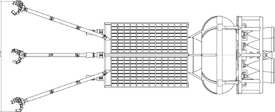
Рис. 2. Общий вид космического сборщика мусора
-
Fig. 2. General view of the space garbage collector
The block of manipulators consists of three manipulators in the form of claws with closing clamps. The advantage of manipulators over other devices is the hard capture of the space garbage and its quick undocking.
In a vacuum, any slightest collision of objects affects the possible deviations of their further trajectories. To ensure reliable docking of the SC with the garbage fragment, it is necessary to provide a sufficiently rigid and effective gripping device.
As grippers, it is proposed to use an adaptive three-fingered gripper (patent WO 2004/028753) [10], shown in fig. 3. The device includes a body with three fingers mounted on it, located at the vertices of an isosceles or equilateral triangle. Each finger consists of three phalanges, the first of which rotates relative to the body, and the second and third phalanges rotate relative to the first and second, respectively, using individual rotary drives with parallel axes of rotation. Each of the fingers is made with the possibility of rotation relative to the body at an angle of at least 90 ° using an individual drive.
A rotary drive is attached to the manipulator, which turns the body with fingers relative to the garbage. Servo drives with built-in indicators are used as individual drives, and the contact surfaces of the phalanges are equipped with tactile sensors for working with objects of different shapes, rigidity and strength. The proposed solution allows to increase the functionality of the manipulator unit and the reliability of grasping objects with a previously unknown shape.
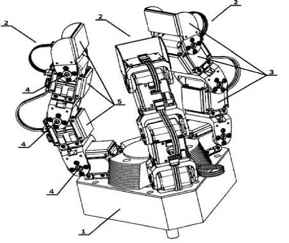
Рис. 3. Захватное устройство:
1 – корпус; 2 – пальцы, 3 – фаланги пальцев; 4 – сервоприводы; 5 – контактная площадка фаланг
-
Fig. 3. Gripping device:
-
1 – body; 2 – fingers; 3 – finger phalanges; 4 – servos; 5 – contact area of the phalanges
The SGC body hardware is a thin-walled anisogrid mesh shell, reinforced at the ends with power frames. A block of manipulators and an engine compartment are attached to the frames from different ends. The design task is to select the optimal parameters of the anisogrid SGC body (shape and cross-sectional area of the ribs, the number of circular and spiral ribs, material characteristics, etc.) that provide the necessary strength and stability of the structure with a minimum weight.
Engine section consists of a propulsion engine that provides interorbital transfers from the waiting orbit to the capture orbit and then to the flooding trajectory and correction engines for correcting the orbits and accurately capturing garbage.
The design model choice. The space garbage collector is a structure with a length of 2686 mm (with arms folded), with a body length of 1600 mm. The diameter of the midsection of the spacecraft is 1200 mm. Therefore, for the calculation of the case, we will take a cylindrical anisogrid mesh shell 1600 mm long and 1200 mm in diameter. This approach simplifies the design model, allowing all external forces to be represented as a combination of longitudinal axial loads. In this case, simplifications in the structure of the hull can be taken into account in the form of a safety factor.
When choosing a design model, it is necessary to analyze the operation of the structure and its individual elements both in the process of launching the spacecraft into the base orbit and during its operation (interorbital crossings, capture of garbage, its transportation and disposal).
To determine the design case, let us consider the location of the spacecraft under the nose fairing of the “Soyuz 2.1b” launch vehicle during the delivery of the payload to the base orbit.
Concentrated forces . Concentrated forces. In the considered design model, under the concentrated forces we mean the pressure distributed along the perimeter of the power frame and applied at the points of attachment of the engine section to it. In addition, we will also refer to external forces as the reactions of the bonds arising on the opposite power frame at the place of attachment of the spacecraft to the head adapter.
The mass of the engine compartment m = 1008 kg is applied to the power support frame -DU control. The power frame on the opposite edge of the SGC body will be taken rigidly attached to the adapter at the place where the payload is installed. A block of manipulators for capturing space garbage located on the power frame and manoeuvrable engines with a total mass of 45 kg are fixed on the same frame and connected to the support attachment to the adapter.
Distributed loads. Distributed loads. In our design scheme, these are inertial forces from the action of the overload at the moment the launch vehicle operates on the active part of the trajectory.
Analysis of the active part of the trajectory made it possible to determine the value of the maximum values of the overload during the launch of the spacecraft into the base working orbit. Let's take them equal to n=5g.
Thus, the design model will take the form shown in fig. 4.
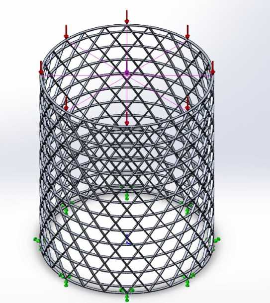
Рис. 4. Расчетная схема сетчатого анизогридного корпуса сборщика космического мусора
Fig. 4. Design model of the mesh anisogrid housing of the space garbage collector
The parametric analysis of the design of the mesh anisogrid body of the SGC includes modelling the following weight and strength characteristics.
-
– determination of the stress-strain state of the design;
-
– determination of the natural frequencies of the design;
-
– determination of the loss margin stability against longitudinal force;
-
– determination of the mass of the body.
Analysis of the calculation results will allow us to choose the optimal design of the anisogrid body for the space garbage collector based on the criteria of strength and weight characteristics.
Finite-element modelling. Finite - element modelling. Composite mesh cylindrical shells are widely used as load-bearing bodies for spacecraft [11; 12]. The cylindrical mesh body is subjected to compressive loads arising from the launch of the spacecraft into orbit. The study of the longitudinal deformation of the mesh body is an important stage in its design. The body of the space garbage collector (SGC) we are designing is a mesh cylindrical shell, one edge of which is fixed, and the other edge is loaded by axial compressive force. The magnitude of the force is equal to the product of the weight of the spacecraft and the maximum axial overload. The displacement of the loaded edge of the shell is a measure of the longitudinal stiffness of the spacecraft mesh body. Loading is carried out through an absolutely hard disk located at the edge of the shell (supporting power frame). To solve a similar problem, the continuum model of the reticular shell has already been used earlier [13; fourteen]. The deformation process is described by the equations of the nonlinear momentless theory of orthotropic cylindrical shells. A formula has been obtained that can be used to determine the displacement of the disk and to estimate the longitudinal stiffness of the mesh cylindrical shell. This formula was used to study the influence of the angle of inclination and the number of spiral ribs on the amount of movement of the end frame.
Let us use the analytical formulas derived in [14] to calculate the displacement of a hard disk attached to a mesh anisogrid shell with different geometric and stiffness parameters under the action of axial loads.
Consider a mesh shell with spiral and annular ribs have the same cross-section and are made of one unidirectional carbon composite. When calculating the displacements of a rigid ring, we will vary the number of spiral ribs and their angle of inclination.
To verify the results obtained using analytical formulas, we will solve the problem of the compression of the mesh shell using the finite element method. Let us define the movement of the hard disk using the MSC Nastran package [15]. A finite element mesh model was created from two-node spatial BEAM finite elements. The disk attached to the shell was modelled using the leaf element RIGID. The size of the beam finite element for all shell models was the same and equal to 10 mm. The displacements of the hard disk, found using the finite element method, are comparable to the values obtained analytically. The maximum relative error between these displacements does not exceed 5%, which confirms the correctness of our adopted finite element model of the anisogrid body of the SGC.
When carrying out a parametric analysis of the anisogrid body of the SGC by the finite element method, we will consider three variants of the mesh composite structure of the ribs (tab. 1).
Table 1
Parameters of the anisogrid structure of the SGC body
|
Varia nt |
Number of unidirectional spiral ribs, pcs |
Rib angle, degrees |
|
1 |
24 |
15 |
|
2 |
30 |
12 |
|
3 |
36 |
10 |
As a material for the SGC body, a carbon matrix with carbon fibre is taken as a reinforcing filler with the кг following physical and mechanical properties: E=170 ГПа, ρ=1550 , σ = 350 МРа.
м
For the three variants of the mesh composite structure of the SGC body chosen (table 1), the maximum values of stresses and strains were determined, as well as the buckling margin in each design case.
The analysis of the stress-strain state made it possible to determine the maximum values of stresses in the structure, as well as the most loaded ribs and sections of the body. In addition, the calculated maximum absolute deformations made it possible to compare them with the standard design tolerance when the payload is located under the nose fairing of the launch vehicle. In each design case, the natural frequencies of the SGC body and the buckling margin were determined.
The results of the parametric analysis of the anisogrid body are shown in table 2.
Results of numerical simulation of the SGC anisogrid body parameters
Table 2
|
Number of spiral ribs |
Angle of inclination of ribs, degrees |
Maximum deformations δ , mm |
Maximum stresses σ , MPa |
Safety factor of buckling |
Constructio n weight, kg |
|
24 |
15 |
1.590 |
67.850 |
1.63 |
157.97 |
|
30 |
12 |
0.920 |
55.200 |
2.45 |
173.69 |
|
36 |
10 |
0.647 |
45.480 |
3.37 |
190.35 |
Based on the results of the parametric analysis, we will accept the body of the space garbage collector in the form of an anisogrid mesh shell with 24 spiral unidirectional ribs (fig. 5, 6).
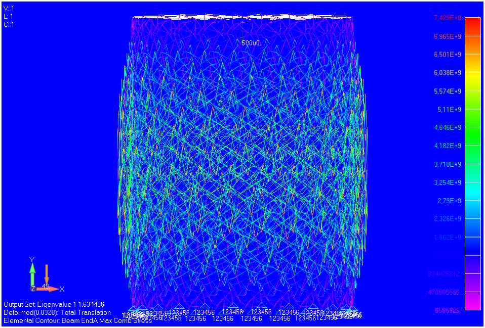
Рис. 5. Потеря устойчивости корпуса КСМ (24 спиральных ребра)
Fig. 5. Loss of stability of the SGC body (24 spiral ribs)
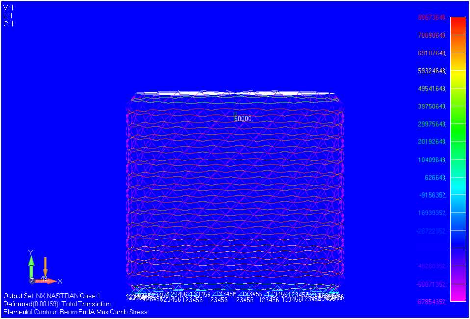
Рис. 6. Напряженно-деформированное состояние корпуса КСМ (24 спиральных ребра)
Fig. 6. Stress-strain state of the SGC body (24 spiral ribs)
σ
At the same time, the buckling margin was 1,63, the safety factor в =350/67,85=5,1. The mass of the σ max mesh anisogrid body was 157, 97 kg.
The total mass of the space garbage collector was m=1243, 35 кг.
Conclusion. The paper presents an approach to solving the problem of designing a space garbage collector (SGC), the body of which is made in the form of a cylindrical mesh anisogrid shell. In this work, a parametric analysis of the anisogrid body of the SGC is carried out. By varying the number and angle of inclination of unidirectional spiral ribs, an optimal design scheme is found that meets the required margin of safety and stability. The main vibration frequency of the body structure is determined, its stress-strain state is investigated and the calculation for stability is carried out.
Based on the results of the parametric analysis of the SGC body, its geometric dimensions were determined and the mass of the space drone structure as a whole was minimized.
References Parametric analysis of the anisogrid body of the spacecraft for cleaning the orbit of space debris
- Chto takoye kosmicheskiy musor i metody bor'by s nim [What is space debris and methods of dealing with it]. Available at: https://bezotxodov.ru/musor/kosmicheskij-musor (accessed: 01.06.2020). (In Russ.)
- Golovko V. Kosmicheskiy musor [Space debris]. Available at: https://naukatehnika.com/kosmicheskij-musor.html (accessed: 11.07.2020). (In Russ.)
- Kolga V. V., Yarkov I. S., Yarkova E. A. Development of the heat panel of the small space apparatus for navigation support. Siberian journal of science and technology. 2020, Vol. 21, No. 3, 382–388. DOI: 10.31772/2587-6066-2020-21-3-382-388.
- Filatov V. V., Yevtif’yev M. D., Lebedeva L. N., Kolga V. V. Sovremennyye otechestvennyye rakety-nositeli. Raketno-kosmicheskaya tekhnika [Modern domestic launch vehicles. Rocket and space technology]. Krasnoyarsk, SibGAU Publ., 2005, 144 p.
- Yevtif'yev M. D., Kovrigin L. A., Kolga V. V., Lebedeva L. N., Filatov V. V. Sovremen-nyye rakety-nositeli zarubezhnykh stran. Raketno- kosmicheskaya tekhnika [Modern launch vehicles of foreign countries. Rocket and space technology]. Krasnoyarsk, SibGAU Publ., 2010, 276 p.
- Testoyedov N. A., Kolga V. V., Semenova L. A. Proyektirovaniye i konstruirovaniye bal-listicheskikh raket i raket nositeley [Design and construction of ballistic missiles and launch vehicles]. Krasnoyarsk, SibGAU Publ., 2014, 308 p.
- Zamyatin D. A., Kolga V. V., Bogdanova V. S. [Methods for protecting spacecraft from external influences]. Мaterialy XХI Mezhdunar. nauch. konf. “Reshetnevskie chteniya” [Materials XХI Intern. Scientific. Conf “Reshetnev reading”]. Krasnoyarsk, 2017, P. 9–11. (In Russ.)
- Zamyatin D. A., Kolga V. V., Bogdanova V. S., Stepanova S. V. [Review of upper stages compatible with the Angara family of launch vehicles]. Мaterialy XХI Mezhdunar. nauch. konf. “Reshetnevskie chteniya” [Materials XХI Intern. Scientific. Conf “Reshetnev reading”]. Krasnoyarsk, 2017, P. 11–13. (In Russ.)
- Zamyatin D. A., Kolga V. V. [Construction of anisogrid power structure of the spacecraft adapter] Мaterialy XХII Mezhdunar. nauch. konf. “Reshetnevskie chteniya” [Materials XХII Intern. Scientific. Conf “Reshetnev reading”]. Krasnoyarsk, 2019, P. 26–28. (In Russ.)
- Townsend W. T., Hauptman T., Crowell A., Zenowich B., Lawson J. Intelligent, self-contained robotic hand. Patent WIPO, №WO2004028753, 2004. Available at: https://pat-entscope.wipo. int/search/en/detail.jsf?docId=WO2004028753&_cid=P20-KKMCUK-92305-1 (accessed: 11.07.2020).
- Vasiliev V. V., Barynin V. A., Rasin A. F., Petrokovskii S. A., Khalimanovich V. I. Anisogrid composite lattice structures – development and space applications. Composites and Nanostructures. 2009, Vol. 3, P. 38–50.
- Vasiliev V. V., Barynin V. A., Razin A. F. Anisogrid composite lattice structures – development and aerospace applications. Composite Structures. 2012, Vol. 94, No. 11, P. 17–27.
- Lopatin A. V., Morozov E. V., Shatov A. V. Buckling of uniaxially compressed composite anisogrid lattice cylindrical panel with clamped edges. Composite Structures. 2017, Vol. 160, P. 765–772.
- Lopatin A. V., Morozov E. V., Shatov A. V. Axial deformability of the composite lattice cylindrical shell under compressive loading: Application to a load-carrying spacecraft tubular body. Composite Structures. 2016, Vol. 146, P. 201–206.
- MSC Nastran. User’s guide: MSC. Siemens Product Lifecycle Management Software Corporation; 2014. P. 886. Available at: https://docs.plm.automation.siemens.com/data_services/resources/ nxnastran/10/help/en_US/tdocExt/pdf/User.pdf (accessed: 11.07.2020).
