Performance Analysis between Analog OFDM & Digital OFDM System

Автор: Pravat Kanti Nath, M. M. Rahman, S. M. Abdur Rahim, Md. Khalid Hossain, Md. Salim Raza, Md. Nasir Uddin Khan
Журнал: International Journal of Wireless and Microwave Technologies(IJWMT) @ijwmt
Статья в выпуске: 4 Vol.6, 2016 года.
Бесплатный доступ
Orthogonal Frequency Division Multiplexing (OFDM) signaling has been widely used for high data rate transmission applications due to its high spectral efficiency and robustness to the frequency selective fading channels. One of the major drawbacks of the analog OFDM system is frequency shifting in every sub-carrier. That's why bit error rate increased in analog OFDM system. In this research, we want to solve the problem of the analog OFDM system by using IFFT circuit instead of the local oscillator. The IFFT circuit takes an input as frequency domain and provides output as a time domain signal for 4-QAM modulation. Basically IFFT circuit acts as a local oscillator in the analog OFDM system. The IFFT circuit only executes operation on a discrete frequency domain signal which is converted into a time domain signal by its. So no frequency shifting occurs in every sub-carrier in the digital OFDM system. As a result BER also decrease in digital OFDM system over the analog OFDM system.
Analog OFDM System, Digital OFDM System, Orthogonal Subcarriers, Low Pass Filter
Короткий адрес: https://sciup.org/15012948
IDR: 15012948
Текст научной статьи Performance Analysis between Analog OFDM & Digital OFDM System
Published Online July 2016 in MECS DOI: 10.5815/ijwmt.2016.04.08
Frequency Division Multiplexing (FDM) is a technique where the main signal to be transmitted is divided into a set of independent signals, which are called sub-carriers in the frequency domain. Thus, the original data stream is divided into many parallel streams (or channels) [1], one for each sub-carrier. Each sub-carrier is then modulated with a conventional modulation scheme, and then they are combined together to create the FDM signal.
*Corresponding author:
Nomenclature
|
OFDM |
orthogonal frequency division multiplexing |
|
IFFT |
inverse fast Fourier transform |
|
QAM |
quadrature amplitude modulation |
|
BER |
bit error rate |
|
FDM |
frequency division multiplexing |
|
ICI |
inter carrier interference |
|
LPF |
low pass filter |
|
FFT |
first Fourier transform |
|
QPSK |
quadrature phase shift keying |
|
LUT |
look up table |
|
CP |
cyclic prefix |
|
ISI |
inter symbol interference |
|
DFT |
discrete Fourier transform |
|
DAB |
discrete audio broadcasting |
In an FDM transmission, the receiver needs to be able to independently recover each of the sub-carriers and therefore these signals need to fulfil certain conditions. For instance, they can have no overlapping spectra so that a bank of filters tuned to each of the different sub-carriers can recover each of them independently. However, practical filters require guard bands between the sub-carrier bands and therefore the resulting spectral efficiency is low.
If the sub-carrier signals fulfil the orthogonality condition their spectrum can overlap, improving the spectral efficiency. This technique is known as orthogonal FDM or OFDM [2] [3] [4]. For an OFDM signal transmission, each small truck represents a sub-carrier, and the roads where data is going to be carried are an analogy of the different frequencies at which each sub-carrier is going to be transmitted. Moreover, each packet containing goods represents the modulated portion of data to be carried by a sub-carrier, which is called an information symbol.
The organization of the rest part of this paper has arranged as follows. In section II, it will be discussed about the basic working principle of analogue OFDM system. The Section III contains basic working principle of digital OFDM system with IFFT/FFT. The section IV and V contain simulation results of analogue OFDM system and digital OFDM system respectively. In the VI, the whole study and research performance will be concluded.
-
2. Analog OFDM Transmitter and Receiver
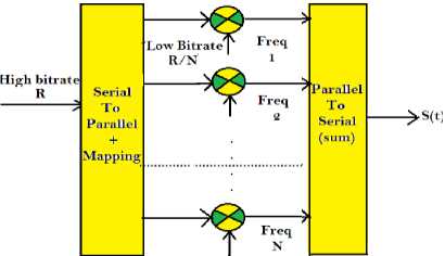
Fig.1 shows the basic model of an analogue OFDM Transmitter. A bit sequence with rate R is parallelized into N different channels, each with a different frequency. The total bit rate is distributed in equal parts over each channel at a rate R/N. The data in each channel will be mapped to represent an information symbol and then multiplied by its corresponding orthogonal time domain subcarriers. The summation of those parallel signals will form time domain base band OFDM signal S(t). The time domain base band OFDM signal S(t) will be transmitted through the wireless medium after mixing of pass band carrier frequency signal. The OFDM signal in the time domain s(t) can be expressed as:
s(0 = ^{^^„ooEk-o Ci, k e^f k t . P(t – i T s )} (1)
Where P(t) is an ideal square pulse of length, the number of sub-carriers is represented by N and f k is the sub-carrier frequency. This frequency has to fulfill the orthogonality condition:
f k = k
k
Each sub-carrier must be separated from its neighbors by exactly 1/ Ts, so each sub-carrier within an OFDM symbol has exactly an integer number of cycles in the interval Ts, and the number of cycles differs by exactly one, as depicted in Fig.2. This way, orthogonality between sub-carriers is achieved [5] – [7]. The orthogonality property can be explained for any couple of sub-carriers by the following expression:
Vt'i cos cos ('—--) ^ = 0 , m ≠ n
J V2 x т ) x i )
If m and n are different natural numbers, the area under this product over one period is zero. The frequencies of these waves are called harmonics and for them the orthogonality condition is always fulfilled. in Figure 3, an OFDM symbol spectrum consists of overlapping sine functions, each one representing a sub-carrier, where at the frequency of the kth sub-carrier all other sub-carriers have zeros.
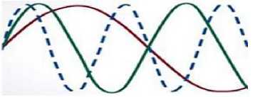
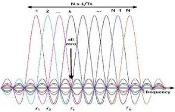
Fig.3.Spectrum of an OFDM Symbol with Overlapping Sub-carriers [8]
he amplitude spectrum of the square pulse P(t) has a form sin( ^t) , which has zeros for all frequencies f that are an integer multiple of 1/Ts. Then as shown The sub-carriers can be recovered at the receiver without inter carrier interference (ICI) despite strong signal spectral overlapping, by means of the orthogonality condition using a bank of oscillators and low-pass filtering for each sub-carrier.
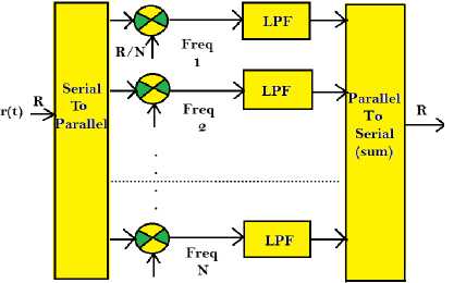
Fig.4 shows the basic model of an analogue OFDM Receiver. The Operation of an analog OFDM receiver just like as reverse operation of analog OFDM Transmitter.
-
3. Digital OFDM Transmitter and Receiver
The model considered for the implementation of the OFDM transmitter is shown in the Fig.5. The serial to parallel converter receive the M serial bits to be transmitted and those bits are divided into N sub-blocks of Mn bits each sub-block.
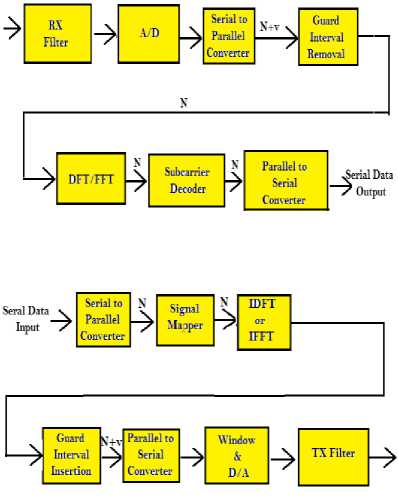
Those N sub-blocks will be mapped by the constellation modulator using Gray codification, this way an+ jbn values are obtained in the constellation of the modulator. The M-QAM encoder converts input data into complex valued constellation points, according to a given constellation, 4-QAM, 16-QAM, 32-QAM and so on. It is necessary to specify how the constellation will be mapped and implement that block. The block encoder can be made by consulting a conversion table, implemented with a LUT (Look Up Table). It is important to note that in that mapping block, bits are converted into complex symbols (pharos) having the information of the constellation. The Inverse Fast Fourier Transform (IFFT) transforms the signals from the frequency domain to the time domain.
The guard interval or cyclic prefix (CP) is a copy of the last N samples from the IFFT, which are placed at the beginning of the OFDM frame. If the number of samples in the CP is large, the data transmission rate will decrease significantly, since the CP does not carry any useful data.
The Functional diagramof the OFDM Receiver are shown in the Fig.6. The received symbol is in time domain and it can be distorted due to the effect of the channel. The received signal goes through a serial to parallel converter and cyclic prefix removal. After the cyclic prefix removal, the signals are passed through an N-point fast Fourier transform to convert the signal to frequency domain. The output of the FFT is formed from the first M samples of the output. The demodulation can be made by DFT or FFT.
At the decoder, a mapped symbol (point) of the transmitted constellation may have changed due to the additive noise in the communications channel, a miss adjustment in the sampling time at the receiver, or several other unwanted causes. Therefore, it is necessary to define a threshold to facilitate the decision making in the receiver constellation. That is the function of the M-QAM decoder [4] [9] [10][11].
-
4. Simulation Result of Analog OFDM System
MATLAB was used here as the image processing tool like other research article [8] [9] [12] [13]. Using this tool, the random data gerenation process of analog OFDM transceiver has analyzed which are described as follows.
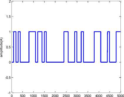
In analog OFDM transmitter, the first step is the random data generation. Random data generator is used to generate a serial random binary data. This binary data stream is the raw information that going to be transmitted. The serial binary data is then fed into OFDM transmitter. Random data was generated using random function of MATLAB® software (shown in fig.7). Here a block of 1024 bits was taken for transmission. Finally random binary data converted in to serial symbols for 4-QAM modulation as shown in fig.8.
time(t)
Fig.7.Generation of Random Binary Data.
The random serial data produced in the previous step were converted to parallel data using serial to parallel (S/P) converter designed in MATLAB. In this research work we have taken four sub-carriers in the OFDM system. Using of four sub-carriers resulted in increment of bit duration four times and decrement of inter symbol interference (ISI) four times (shown in Fig.9).
For mapping, in this research work, we have used 4-QAM modulation technique. In the 4-QAM modulation technique, each symbol carries two bit binary data. The symbol corresponds to each sub-carrier mapped into a 4-QAM format. Since differential encoding requires an initial phase reference, an extra symbol was added at the start for this purpose. The data on each symbol was then mapped to a combined form of amplitude and phase angle based on the modulation technique as shown in Fig.10. As for example (4+4j), (4-4j), (-4+4j), (-44j) points were taken for symbol 0,1,2,3 respectively. The (4+4j), (4-4j), (-4+4j), (-4-4j) points were considered as frequency domain complex symbols.
2 0
parallel symbol for sub carrier 1

0 2 4 6 8 10 12 14 16
n(discrete time)
parallel symbol for sub carrier 2
4 6 8 10 12 14 16
n(discrete time)
parallel symbol for sub carrier 3
^ 0f090???f90900 D
0 2 4 6 8 10 12 14 16
n(discrete time)
parallel symbol for sub carrier 4
024 L 9 0 0 T 0 ? f T f ? 0 ? 9 Д
E 0 2 4 6 8 10 12 14 16
n(discrete time)
Fig.9.Parallel symbolic Information Corresponding to Four Sub-carriers.
In-Phase
Fig.10.Mapping of 4-QAM Modulation
The four time domain orthogonal sub-carriers for every first symbol corresponding every first sub-carrier as show in fig.11. The four time domain orthogonal time signal combines together. So we get time domain OFDM signal as show in fig.11.
time(second)
x 10-6
The analog OFDM receiver receives original OFDM signal that would be bemodified by noise [14] [15]. We have consider the AWGN channe in this sdimulation.l First step of receiving function was to remove the noise from the received signals. Noise removal was done by using Butterworth low pass filter. Fig.12 shows the signals after noise filtering.Apply 4-QAM de-modulation on received OFDM signal and we get four Parallel Symbols corresponding four sub-carrier is shown in fig.13. The four parallel symbols convert into serial symbols as shown in fig.14.
The function of the last stage of the receiver is to recover the original binary data. At first, de-mapping operation was applied on complex frequency domain symbol corresponding to each sub-carrier. These parallel data were then passed through a parallel-to-serial converter to recover the original binary data stream (Fig.15)
time(second) -5
4f$-------Ф-------1 О 1 0 6f
02 Г 9 I e T ? H ? e M e M e j
0 2 4 6 8 10 12 1416
n(discrete time) parallel symbol reobtaion from sub carrier 2
c 24 m 1 11
0L—9—1—5—@—©—©—I—9—©—I—0—©—©—©—I—1
E 0 2 4 6 8 10 12 1416
n(discrete time) parallel symbol reobtaion from sub carrier 3
024 ^е^еФ0???Тфе9ееТ^
E 0 2 4 6 8 10 12 1416
n(discrete time) parallel symbol reobtaion from sub carrier 4
I 024^
e9eete?!ff?e?9
E 0 2 4 6 8 10 12 1416
n(discrete time)
time(t)
Fig.15.Recovering the Original Binary Data Stream
-
5. Simulation Results of Digital OFDM System
The random data generator is the important of the transmitter section which generates random data. The simulation sequence of the transmitter section has been discussed as follows.
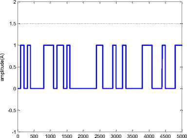
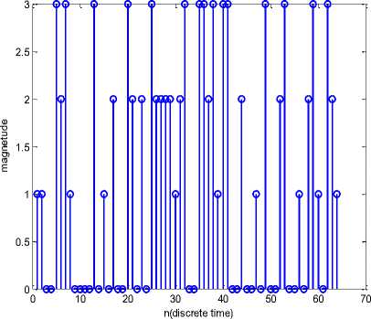
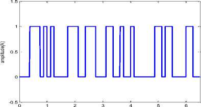
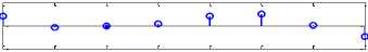
The first step of the transmitting process is the random data generation. Random data generator is used to generate a serial random binary data. This binary data stream models the raw information that going to be transmitted. The serial binary data is then fed into OFDM transmitter. Random data was generated (shown in Fig.16) using random function of MATLAB® software. Here a block of 1024 bits was taken for transmission.
The random serial data produced in the previous step were converted to parallel data using serial to parallel (S/P) converter designed in MATLAB. In this study we have taken four sub-carriers in the OFDM system (shown in Fig.17). Using of four sub-carriers resulted in increment of bit duration four times and decrement of inter symbol interference (ISI) four times.
time(micro second)
Fig.16.Generation of Random Binary Data parallel binary information for subcarrier-1 to be transmitted
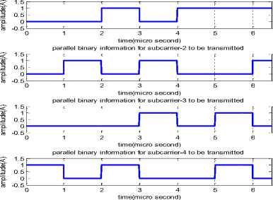
Fig.17.Parallel Binary Information corresponding to Four Sub-carriers
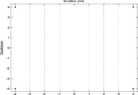
In this research work, we have used 4-QAM modulation technique. In the 4-QAM modulation technique, each symbol carries two bit binary data. The symbol corresponds to each sub-carrier mapped into a 4-QAM format. Since differential encoding requires an initial phase reference, an extra symbol was added at the start for this purpose. The data on each symbol was then mapped to a combined form of amplitude and phase angle based on the modulation technique. As for example (4+4j), (4-4j),(-4+4j),(-4-4j) points were taken for symbol 0,1,2,3 respectively in Figure-18. The (4+4j), (4-4j), (-4+4j), (-4-4j) points were considered as frequency domain complex symbols.
Scatter plot
-1 0 1
In-Phase
Fig.18.Mapping Of 4-QAM Modulation.
In the real world, only time domain signals propagate through wireless medium. So the frequency domain signals were converted to the time domain complex symbols. This operation was done IFFT operation..
To overcome inter symbol interference (ISI) between two successive time domain symbols, a guard interval was added to the start of every time domain symbol corresponding every sub-carrier. The type of guard period used in this simulation was a cyclic extension of the symbol. The length of guard period was chosen 25 percent of the length of symbol.
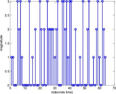
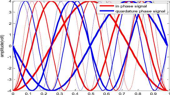
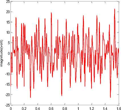
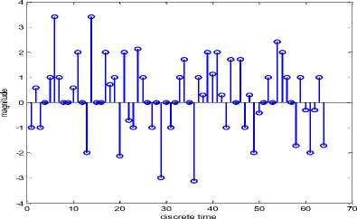
In this research work we are used four sub-carriers and four IFFT/FFT points. The first point of IFFT circuit generates time domain symbols corresponding to first sub-carrier. Similarly second point of IFFT circuit generates time domain symbols corresponding to second sub-carrier and so on. The OFDM signal is a combined form of the time domain sub-carrier signals added sequentially. The addition function was done by P/S converter that generates discrete time OFDM signals as shown in Fig.19.
The discrete time OFDM signal cannot transmit through wireless medium due to the requirement of infinite bandwidth. The discrete time OFDM signal was converted to analog form (Fig.20(a)) for transmission through wireless medium. This function of digital to analog conversion was done by simulation.
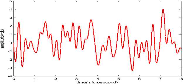
Fig.20.(a) Conversion of Discrete Time OFDM Signal to Continuous Time OFDM Signal. These Signals are Transmitted Wirelessly through Free Space
Finally this OFDM signal transmitted through the wireless medium which modified the orginal OFDM signal by noise as shwon fig20(b) . In this simulation , we have consider AWGN channel
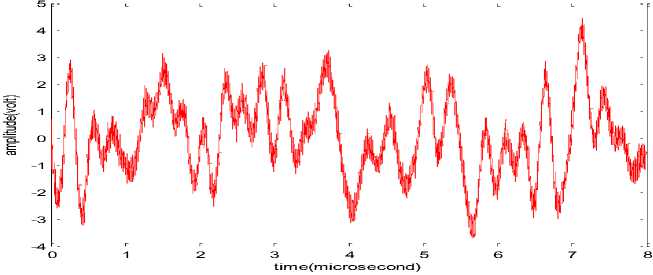
Fig.20.(b) Transmitted OFDM Signal after Noise Addition Considering AWGN Channel
The Digital OFDM receiver basically does the reverse operation of the transmitter. The guard period is removed and the FFT of each symbol is then taken to find the original transmitted spectrum. The phase angle of each transmission carrier is evaluated and converted back to the data word by demodulating the received phase. The data words are then combined back to the same word size as the original data and converted back to original binary form. The step by step description of receiving operation is given below:
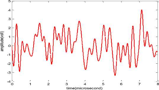
Receiver receives signals which is the original OFDM signal modified by noise. First step of receiving function was to remove the noise from the received signals. Noise removal was done by using Butterworth low pass filter. Fig.21 shows the signals after noise filtering.
The analog signal cannot directly apply to FFT portion of OFDM receiver because FFT circuit executes operation based on discrete time signal. The A/D converter converts analog signals to discrete time OFDM signals as shown in Fig.22.
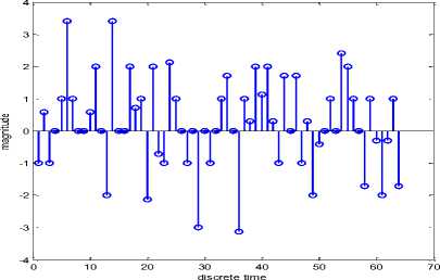
Fig.22.Discrete Time OFDM Signal after Analog to Digital Conversion at the Receiver
-5
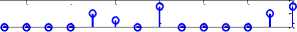
parallel discrete time signal crospondig subcarrier-1
;------------$------®------е------°------е------^ 12345678
discrete time
parallel discrete time signal crospondig subcarrier-4
-5
discrete time
Fig.23.Parallel Discrete Time Signal Corresponding to Every Sub-carrier
parallel binary information reobtaion corsponding subcarrier-1
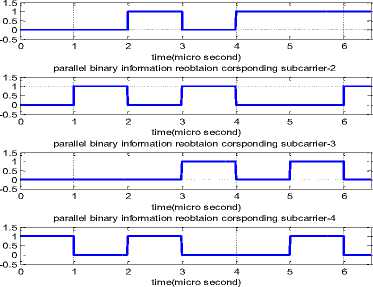
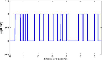
Fig.25.Recovering the Original Binary Data Strea
In Parallel (S/P) Conversion of Discrete Time OFDM Signal, carriers were removed from the discrete time OFDM signals. This was done by serial to parallel conversion. The resulting signals are shown in Fig.23.
In transmitter, a guard interval was added in front of every symbol to minimize ISI (Inter Symbol Interference). In this step the guard periods from the symbols were removed. Also parallel discrete time domain signals were converted to discrete frequency domain signal by applying FFT operation.
The function of the last stage of the receiver is to recover the original binary data. At first, de-mapping operation was applied on complex frequency domain symbol corresponding to each sub-carrier (Fig.24). These parallel data were then passed through a parallel-to-serial converter to recover the original binary data stream (Fig.25).
-
6. Conclusions
One of the main reasons to use OFDM is to increase robustness against frequency-selective fading or narrowband interference. In a single-carrier system, a single fade or interferer can cause the entire link to fail, but in a multi-carrier (MC) system, only a small percentage of the sub-carriers (SCs) will be affected. The difference between the conventional non-overlapping MC technique and overlapping MC technique is, we save almost 50% of the BW in the latter case. To realize this, however, we need to reduce cross-talk between SCs, which means that we want orthogonality between the different modulated carriers OFDM is a modulation scheme that is especially suited for high-data-rate transmission in delay-dispersive environments. It converts a high data stream into a number of low-rate streams that are transmitted over parallel, narrowband channels that can be easily equalized.
We have been seen that from simulation result for analog OFDM simulation, the carrier frequency generated by local oscillator but local oscillator cannot provide stable frequency. Hence frequency shifting occurs in each sub-carrier due to unstable effect of local oscillator. As a result analog OFDM system cannot full fill orthogonalilty condition. So bit error probability increase in analog OFDM system due to the used of local oscillator. This problem also solved by using IFFT circuit instead of local oscillator. The IFFT circuit takes an input as frequency domain and provides output as time domain signal for 4-QAM modulation. Basically IFFT circuit acts as local oscillator in analog OFDM system. The IFFT circuit only execute operation on discrete frequency domain signal which is converted in to time domain signal by its. So no frequency shifting occurs in every sub-carrier in digital OFDM system. Hence digital OFDM system carefully fulfilled Orthogonality condition for every sub-carrier. As a result BER also decrease in digital OFDM system over analog OFDM system. That why we have conclude that digital OFDM system more preferable over analog OFDM system.
Acknowledgements
We would like to thank all concerned with the AECE department for their all-out effort to support us for completing this research.
Список литературы Performance Analysis between Analog OFDM & Digital OFDM System
- Salzburg, Dec. 1967, Performance of an efficient parallel data transmission system, IEEE Trans. Comm, Vol. Com-15, pp-805-813.
- Edfors O., Sandell M., Van de Beek J. J., Landstrom D. and Sjoberg, 1996, An Introduction to OFDM, Lulea Sweden: Lulea Tekniska University, pp-1-58.
- Md Salim Raja, Md. Imran Hossain, Md. Khalid Hossain Jewel, Md Shahjahan Ali, PAPR Reduction of OFDM Signal Using Sequential Phase Sequence SLM Based Transceiver without Side Information. I.J. Wireless and Microwave Technologies, 2015, 1, 34-42. http://www.mecs-press.net/ijwmt
- Paterson, K. "Generalized Reed-Muller codes and power control in OFDM modulation" IEEE Trans. Inform. Theory, vol. 46, no. 1, pp. 104–120, Jan. 2000.
- R. van Nee and R Prasad, OFDM for Wireless Multimedia Communication, Artech House Publishers Boston, USA
- R. van Nee, 1999, A new OFDM standard for high rate wireless LAN in the 5 GHz band, Proceeding of the IEEE vehicular Technology Conference, pp-258-262.
- J. G. Proakis, 1995, Digital Communication, Mc Graw Hill, New York, USA, 3rd ed.
- Fred Buchali, Roman Dischler and Xiang Liu, "Optical OFDM: A Promising High-Speed Optical Transport Technology" (Bell Labs Technical Journal, 2009)
- Urmila Suhagiya; Prof. R. C. Patel, 2014, Design and Implementation of OFDM Transmitter and Receiver using 8-point FFT/IFFT, international journal of software and hardware research in engineering, vol-2, pp-19-23.
- Yusof, S.K. and N. Fisal, "Correlative Coding with Clipping and Filtering Technique in OFDM Systems" ICICS-PCM 2003, Singapore, IEEE 2003, pp.1456-1459.
- Li, X. and L. J. Cimini, Jr., "Effect of clipping and filtering on the performance of OFDM", IEEE Commun. Lett., vol. 2, no. 5, pp. 131-133, 1998.
- Rahman, M. A., Alam, M. M., Hossain, M. K., Islam, M. K., Uddin, K. M. N. and Shahinuzzaman, M. "Performance Evaluation of a DS-CDMA System in a Rayleigh Fading Environment", World Journal of Engineering and Technology, 2015, Vol.4, No.1, PP. 1-9. http://dx.doi.org/10.4236/wjet.2016.41001
- Firoz, M.R., Ali, M.S., Uddin, K.M.N., Hossain, M.K., Islam, M.K. and Shahinuzzaman, M. Medical Image Enhancement Using Morphological Transformation. Journal of Data Analysis and Information Processing, 2016, Vol. 4, No.1, PP. 1-12. http://dx.doi.org/10.4236/jdaip.2016.41001
- Ochiai, H. and H. Imai, "Performance of the deliberate clipping with adaptive symbol selection for strictly band-limited OFDM systems", IEEE J. Sel. Areas Commun., vol. 18, pp. 2270-2277, 2000.
- Wu, Y. and W. Y. Zou, "Orthogonal frequency division multiplexing: A multi-carrier modulation scheme," IEEE Trans. Consumer Electronics, vol. 41, no. 3, pp. 392–399, 1995.
