Performance Analysis of Differential Evolution Algorithm based Beamforming for Smart Antenna Systems

Author: Amara Prakasa Rao, N.V.S.N.Sarma
Journal: International Journal of Wireless and Microwave Technologies(IJWMT) @ijwmt
Article in issue: 1 Vol.4, 2014.
Free access
This paper presents smart antenna array beamforming using differential evolution algorithm. The excitation values of the elements in the array are smartly adjusted to control side lobe levels and placing nulls in the interference signal direction while maintaining the beam in the desired signal direction. Different cases are considered to illustrate the performance of this technique. Simulation results show that this evolution algorithm is better than the traditional beamforming algorithms for Smart antenna systems.
Array Factor, Beamforming, Differential Evolution Algorithm, Null Steering, Smart Antenna Array
Short address: https://sciup.org/15012852
IDR: 15012852
Text of the scientific article Performance Analysis of Differential Evolution Algorithm based Beamforming for Smart Antenna Systems
Published Online January 2014 in MECS DOI: 10.5815/ijwmt.2014.01.01
A smart antenna, performs adaptive beamforming and interference suppression, is expected to significantly increase the system capacity and extend the coverage for wireless communication systems [1]. The smart antenna is a promising technology. The main advantage of the smart antenna system is its ability to steer beams towards desired users and place nulls towards interfering signals in the coverage area/network.
The smart antenna array basically consists of a number of antenna elements combined via weight control network to generate a desired antenna beam pattern under dynamic channel environment. Signal processing techniques and evolutionary algorithm are used to adjust the weights of the array to meet the desired response of the system. The evolutionary algorithms such as genetic algorithms, ant colony optimization, differential evolutionary algorithm, particle swarm optimization, and bees algorithm can produce an optimum solution for the problem [2-9].
A.Tennant et al., 1994 [2] addressed the element position perturbations based on the genetic algorithm are used for beamforming of linear arrays. G.K.Mahanti et al., 2007 [3] presented a real coded genetic algorithm is used for the design of fully digital controlled reconfigurable array antennas with fixed dynamic range ratio.
* Corresponding author.
S.Yang et al., 2004 [4] discussed differential evolution algorithm is applied to null steering of linear arrays by controlling the element excitation amplitudes. S.R.Muhammad et al., 2010 [5] compared the performance of least square based algorithms for smart antenna system. In [6] and [7] the synthesis of linear array beamforming is discussed by ant colony and particle swarm optimization techniques respectively. In the present study, placing a deep null in the undesired direction and side lobe reduction are considered.
The organization of the paper is as follows: Section 2 presents the problem formulation. In Section 3, the procedure of differential evolution algorithm discussed. The simulated results are presented in Section 4. In Section 5 some conclusions and summary on the performance of the algorithm are discussed.
-
2. Mathematical Model
The basic concept of deploying smart antenna system in modern communication is illustrated in Fig. 1. The geometry of the array is shown in Fig. 2. For the uniform linear array of N elements with the inter-element spacing d.
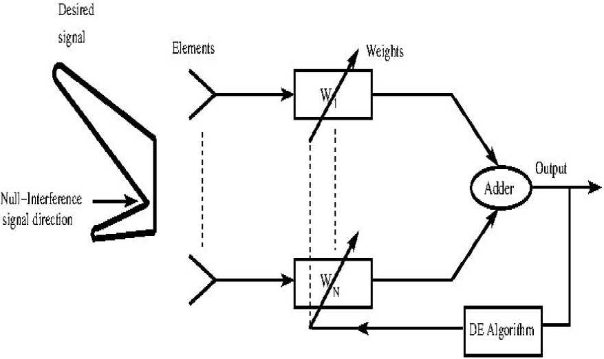
Fig.1. Block diagram of Smart Antenna Array Beamforming Concept.
The adaptive array factor for the far field is given by [10]
AF (9) = Z ^= i Wn e№ ~ 1 )Mc0s 8
where N is number of elements in the array, 9 is an incident angle of interfering signal or desired signal with respect to array normal, to n is the weight coefficient of the n th element. The problem is defined as the optimization of the excitation weights of the array to meet the desired pattern.
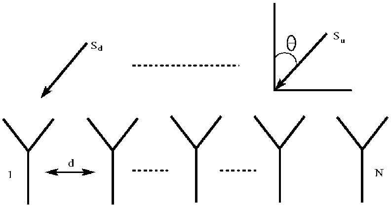
Fig. 2. Geometry of the N elements linear array.
-
3. Differential Evolution Algorithm
Differential Evolution (DE), proposed by Storn and Price [11-12], is a simple yet powerful algorithm for real parameter optimization. Like other evolutionary algorithms DE is an iterative search method and has some processes called mutation and crossover. This paper describes a family of improved variants of the DE/best/2/exp scheme, which utilizes the neighbourhood mutation operator.
The steps involved in this algorithm are discussed briefly here. The details can be found in [13]:
-
(a) Generate an initial population of NP D-dimensional parameter vectors representing the candidate solutions. The following pseudo-code is used to generate initial population.
for i = 1: NP pop(i,:) = Xmin + rand(1,D) .* (Xmax – Xmin); end
-
(b) After initialization, fitness of the population is calculated based on cost function.The cost function used in optimization process is defined as:
= ∑ | AF(θi)| + SLL
where M is the number of nulls in the radiation pattern, θi is null location in the direction of undesired signal, and SLL is the desired side lobe level. Based on cost function (2) value of the initial generation, best one is selected from this set so far.
-
(c) Now, Donor vectors are created by using mutation operation. The general convention used for naming the various mutation strategies is DE/x/y/z, where DE stands for differential evolution, x represents a string denoting the vector to be perturbed, y is the number of difference vectors considered for perturbation of x, and z stands for the type of crossover being used. Most frequently used different strategies are given below [12].
Strategy:
1——DE/best/1/exp
2——DE/rand/1/exp
3——DE/rand-to-best/1/exp
4——DE/rand/2/exp
5——DE/best/2/exp
6——DE/best/1/bin
7——DE/rand/1/bin
8——DE/rand-to-best/1/bin
9——DE/best/2/bin
10——DE/target-to-best/1/bin
Generate donor vectors based on one of the strategies of DE is used.
-
(d) To explore the space diversity of the population, a crossover operation comes after mutation operation. Here trial vectors are generated using crossover operation on donor and target vectors.
-
(e) Calculate the fitness of trial vectors using cost function.
-
(f) Compare local best value of the trial vectors to the best value of the target vectors and select best vector for next generation. The following pseudo-code is used to generate donor, trial vectors and best population of next generation.
while (iter ≤ itermax)
do for i = 1:NP costval(i) =feval(costfun, pop(i,:));
end for i loop
[costvalsort, costvalsortindex] = sort(costval);
Bestmem = pop(costvalsortindex( 1 ),:);
Best(iter) = costvalsort( 1 );
for j = 1:NP if μ = rand < CR;
Generate donor vector based on one of the mutation schemes of DE. Generate trial vector using binomial or arithmetic crossover.
for k = 1 : D tempval(k) = feval(costfun,tr(k,:));
end for k loop
[sorttempval,sorttempindex] = sort(tempval);
newpop(j,:) = tr(sorttempindex(1),;);
else newpop(j,:) = pop(j,:);
end if end for j loop for i = 1 : NP pop(i,:) = newpop(i,:);
end for i loop iter = iter +1;
end while
-
4. Simulation Results
-
4.1. Radiation Patterns:
Consider a linear array with the following specifications: Number of elements in the array: 20, Inter element spacing in the array: 0.5λ, Number of iterations: 100, Initial Population: 15, Crossover CR: 0.8 and Constant Value F: 0.6.
In the first case, consider two interference signals are intercepting the array at 250 and 450 direction. By applying Differential Evolution algorithm with crossover CR= 0.8 and mutation factor = 0.6 on this linear array of 20 elements, the radiation pattern of this result is shown in Fig. 3 with null depth of -55 dB and -63 dB at undesired signal directions respectively. It is observed that the ratio between the powers of the main lobe and the first side lobe is -16.5 dB. The half power beam width is 12.60.
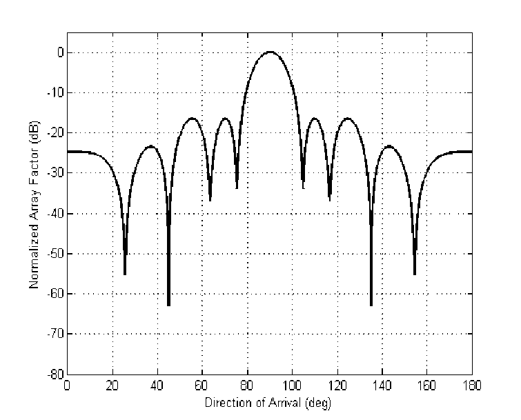
Fig. 3. Radiation pattern of 20 elements linear array with null depths at 250 and 450 of the interference signals direction.
In the second case, the cost function is considered only for the side lobe levels. The response for this case is shown in Fig. 4 with all lobes below -22 dB level. Signal to noise ratio is improved since all side lobe levels are much below the desired side lobe level. The beam width is 300 measured between the first two nulls on either side of the radiation pattern. The half power beam width is 11.80.
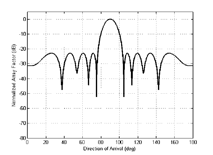
Fig. 4. Radiation pattern of 20 elements linear array with side lobe level control.
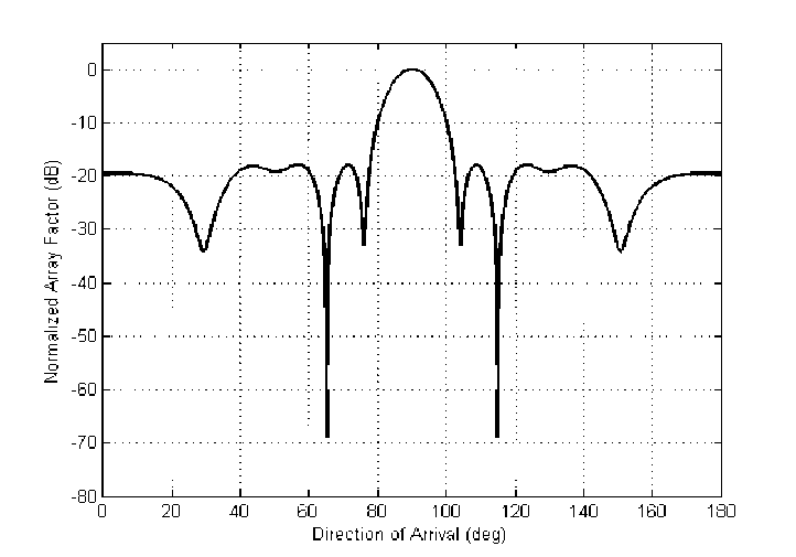
Fig. 5. Radiation pattern of 20 elements linear array with side lobe level(SLL) and a null at undesired signal direction at 650.
In the third case, both the side lobe reduction and placing a null in undesired signal direction is considered as the cost function. Consider that the interference signal is at 650. Using DE both parameters are controlled.
Deep null is placed in the direction of the interference signal as shown in Fig. 5 with -68.5 dB level. Also it can be noticed that all side lobe levels are below -18 dB.
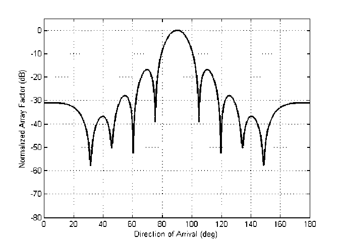
Fig. 6. Placement of nulls in the direction of undesired signals at 300, 450, and 600 in the radiation pattern.
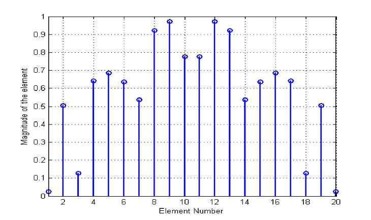
Fig.7. Amplitude of the elements in the 20 elements linear array.
In this section three interference signals are intercepting the array at 300, 450, and 600 respectively. Using differential evolution algorithm, nulls are placed at undesired signal directions. Hence the signal to noise ratio is improved. The response for the case is shown in Fig. 6. All three nulls are having deep depths of -58 dB, -50 dB, and -52.5 dB respectively at undesired signal directions. It is observed that all side lobe levels are below the -18 dB and half power beam width of the main beam is 120. Fig. 7 illustrates the excitation of the elements in the array.
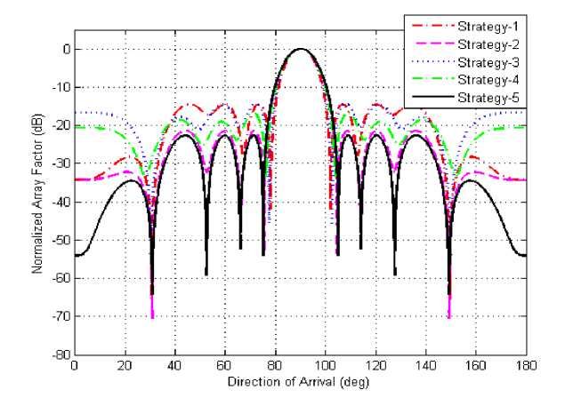
Fig.8. Comparison of the radiation patterns of the 20 elements linear array by using DE with different strategies.
In this paper the first five strategies are considered and their performance is compared. Out of the five strategies, the strategy 5 produced the best results. Except 1 and 2, the other three strategies performed good. But in the case of strategy 5, all the side lobe levels are much below the specified level. The directivity of radiation pattern is improved by strategy 5, by placing deep null in the undesired signal direction. It can be observed in Fig. 8. The half power beam width is 120. The beam width is 300 measured between the first two nulls on either side of the main beam. Signal to Noise interference ratio is improved by suppressing all the side lobe levels to less than -22 dB. Deep null is placed in the direction of undesired signal at 300 by this strategy.
-
5. Conclusion
In this paper, placing the deep nulls in the directions of the undesired signal by using differential algorithm is studied. Different cases are considered to control side lobe levels and placing nulls at interference signal directions in the radiation pattern.
References Performance Analysis of Differential Evolution Algorithm based Beamforming for Smart Antenna Systems
- J.H. Winters, “Smart Antennas for Wireless Systems,” IEEE Personal Communications, Vol.4, No.11, pp:23-27, Feb.1998.
- A. Tennant, Dawoud M.M, Anderson A.P, “Array pattern nulling by element position perturbations using a Genetic Algorithm,” Electron Letters, Vol.30, pp:174-176, 1994.
- G.K. Mahanti, Chakraborty A, Das S, “Design of fully digital controlled reconfigurable array antennas with fixed dynamic range ratio,” Journal Electromagnetic Waves Applications, Vol.21, pp:97-106, 2007.
- S. Yang, Gan Y.B, Qing A, “Antenna array pattern nulling using a Differential Evolution Algorithm,” Int.J RF Microwave CAE, Vol.14, pp:57-63, 2004.
- S.R. Muhammad, Noor M Khan, “Performance Comparison of Adaptive Beamforming Algorithms for Smart Antenna Systems,” World Applied Sciences Journal, Vol.11(7), pp:775-785, 2010.
- D. Karaboga, Guney K, Akdagli A, “Antenna array pattern nulling by controlling both amplitude and phase using modified touring Ant Colony Optimization Algorithm,” Int J Electron, Vol.91, pp:241-251, 2004.
- J.R. Perez, J.Basterrechea, “Hybrid Particle Swarm-based Algorithms and their application to linear array synthesis,” PIER 90, pp:63-74, 2009.
- Bao. Zheng, Renbiao, “Control of Peak Sidelobe Level in Adaptive Arrays,” IEEE Transactions on Antennas and Propagation,” Vol.44, No.10, pp:1341-1347, October 1996.
- H. Chao-Hsing, “Optimizing Beam Pattern of Adaptive Linear Phase Array Antennas using Local Genetic Algorithm,” IEEE Antennas and Propagation Society International Symposium, Vol.1B, pp:315-318, 2005.
- C.A. Balanis, “Antenna Theory Analysis and Design,” Wiley-India, Second Edition.
- R. Storn,K.Price, “Differential Evolution-A Simple and efficient heuristic for global optimization over continuous spaces,” Journal of Global Optimization, Vol.11, No.4, pp:341-359, 1997.
- K.V. Price, R.M. Storn, J.A. Lampinen, “Differential Evolution- A practical Approach to global optimization,” Springer,2005.
- Sk.M. Islam, S.Das, S.Ghosh, S.Roy, and P.N.Suganthan, “An Adaptive Differential Evolution Algorithm with Novel Mutation and Crossover Strategies for Global Numerical Optimization,” IEEE Transactions on systems, man, and cybernetics-part B: cybernetics, Vol.42, No.2, pp:482-500, April 2012.
