Performance Analysis of Multi Functional Bot System Design Using Microcontroller

Author: Vaibhav Bhatia, Pawan Whig
Journal: International Journal of Intelligent Systems and Applications(IJISA) @ijisa
Article in issue: 2 vol.6, 2014.
Free access
This paper includes performance analysis of a multipurpose microcontroller based system which has various modes to control distinct applications. The paper elucidates how a single chip microcontroller can process different signals and accomplish different tasks. The system discussed in this paper has seven modes. Each mode controls different applications. Radio frequency signals are used for controlling the system wirelessly and each mode is triggered by giving a suitable 4-bit logic by the transmitter. The different modes which the system works in consist of security tracking, temperature measurement, sound actuated control, voltmeter mode, door automation, pits avoider and obstacle avoider. The versatility of the system is tested using Xilinx software v10.1. It is found that the system is functioning properly under normal conditions and the variations of the different parameters for a particular mode have been plotted in MATLAB R2013a v8.1 to validate the accuracy of the system.
Microcontroller, Infrared Sensor, Light Dependent Resistor, Radio Frequency, Condenser Microphone, Liquid Crystal Display, Temperature Sensor
Short address: https://sciup.org/15010530
IDR: 15010530
Text of the scientific article Performance Analysis of Multi Functional Bot System Design Using Microcontroller
Published Online January 2014 in MECS
In today’s age of electronics, versatility is demanded in all disciplines. The multifaceted properties of any system have become the heartthrob of everyone in the society [1-2]. A microcontroller is a type of microprocessor furnished in a single integrated circuit and needs minimum of support chips. Most of the latest technologies have microcontrollers embedded in them for carrying out autonomous operations and taking smart decisions [3]. Microcontrollers help in accomplishing so many of the tasks with ease and in accurate manner. Microcontrollers are used in automatically controlled products and devices, such as automobile engine control systems, implantable medical devices, remote controls, office machines, appliances, power tools, toys and embedded systems [4]. By reducing the size and cost compared to a design that uses a separate microprocessor, memory, and input/output devices, microcontrollers make it economical to digitally control even more devices and processes [5-8].
|
Table 1: Microcontroller System |
||
|
CPU |
RAM |
ROM |
|
I/O |
TIMER |
SERIAL COM |
Table.1 shows the microcontroller system. A microcontroller has a CPU in addition to a fixed amount of RAM, ROM, I/O ports and timer all on a single chip. Some microcontrollers may use four-bit words and operate at clock rate frequencies as low as 4 kHz, for low power consumption (single-digit milliwatts or microwatts) [9]. At some places microcontrollers serve performance critical roles, where they act more like a digital signal processor (DSP), with higher clock speeds and power consumption [10].
This paper is organized as: Section-II describes the various modes in the system, Section-III shows the block diagram of the system, Section-IV describes the power supply schematic, Section-V describes the simulation of the circuit, Section-VI discusses the results, and Section-VII shows the conclusions and future scope.
-
II. Various Modes
-
2.1 ST Mode ( Security Tracking Mode)
-
2.2 TM Mode ( Temperature Measurement Mode)
-
2.3 SA Mode (Sound Actuated Mode)
The microcontroller used in the design and implementation of versatile system consists of Peripheral Interface Controller (PIC) family based on modified Harvard architecture developed by microchip technology. It is a 40 pin DIP IC package having inbuilt analog to digital converters for processing analog signals. Liquid Crystal Display (LCD) is used to display the information regarding various modes and showing the mode of operation. The multi-featured system developed consists of seven distinct modes assigned for a particular application. Radio transmitter and receiver have been used to control the system wirelessly. The various modes are described in the following section:
The first mode is security tracking mode, which has been accomplished by the use of infrared sensors. In this mode, system keeps the track of the visitors entering in hi-tech buildings for security purposes. Whenever a visitor enters, visitor-in register adds one and whenever the visitor exits, the visitor-out register adds one. Conventional designs are found with the counter keeping track of only currently present persons. In this system, a new idea for the security of hi-tech buildings has been proposed in which three registers are used, one for counting person’s entry, another for person’s exit and last for counting total persons present at a time in the building. This method overcomes the limitation in the conventional design i.e. tracking only total entries and the exits of the persons at a particular time. The information how many people visit that place in a particular day is very important to do various analyses.
The second mode is the temperature measurement mode which uses LM-35 temperature sensor for the measurement of room temperature. The relationship between digital voltage and temperature is shown in Fig.1. It is found that the digital voltage is varying linearly which shows accuracy of the system. The sensor is interfaced to the analog port of the microcontroller which has inbuilt 10-bit ADC to convert analog signals to digital signals. The room temperature is displayed on the LCD giving the indication of change in temperature. During the peak hours when temperature of the hall rises above the threshold, a control signal is generated which turns on the ventilation system. This mode is important for automatic ventilation of the hi-tech buildings.
The third mode is the sound actuated appliance control which uses a condenser microphone. The control of home appliances can be done by a loud noise or just by a clap. The condenser microphone being a transducer converts the sound into electric signal which is amplified by a transistor and is connected to the analog port of the microcontroller. The voltage of the signal is compared with a reference voltage signal and appliance is made on/off depending on its value exceeds the threshold or not. Relay is used to control the appliances through the microcontroller. The advantage of SA mode is to control the appliances remotely by sound .The schematic of SA mode is shown in Fig.2.
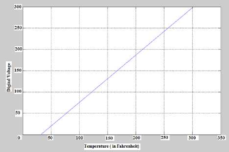
Fig. 1: Digital voltage vs. Temperature (oF)
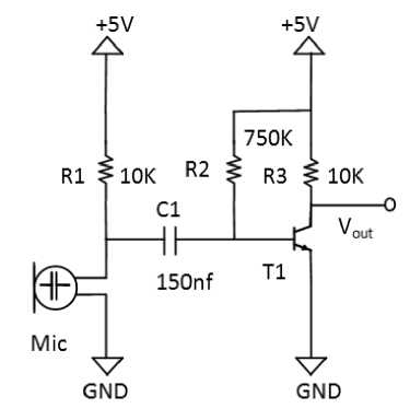
Fig. 2: Sound control schematic
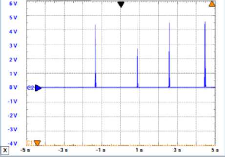
Fig. 3: Voltage peaks vs. Time
Fig.3 shows the voltage peaks vs. time plot. It shows the peaks of voltage produced in the SA mode when a sound is actuated which is being converted into the voltage by the condenser microphone.
-
2.4 VM Mode (Voltmeter Mode)
-
2.7 OA Mode (Obstacle Avoider Mode)
The fourth mode is the voltmeter mode. It uses a simple voltage divider network to measure the voltage at any point in a circuit. The voltage to be measured is applied as the input and the resistances are selected in such a way that output voltage does not exceed +5V, which is the maximum voltage that a microcontroller works upon. For safety of operation, a zener diode has been used as a voltage regulator to limit the output to +5V. This output voltage is measured by the microcontroller and the corresponding input voltage is displayed on the LCD.The Fig.4 shows the relationship between the voltage to be measured and the digital voltage corresponding to the microcontroller. The voltage to be measured depends on the voltage divider network and in this circuit the maximum voltage that can be measured is 25 Volts and it can be further extended to a desired value.
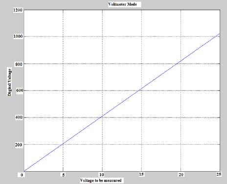
Fig. 4: Digital voltage vs. Voltage to be measured automation of the car. By getting a signal through IR sensors, the system will avoid the pits and ensure a flawless journey. This technology reduces the chances of accidents and mishappenings can be reduced.
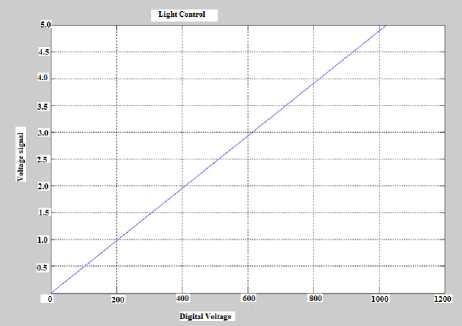
Fig. 5: Voltage signal vs. Digital Voltage
The seventh mode is obstacle avoider mode. In this mode ,the system will avoid the unwanted obstacles coming in its way. This system can be installed on the vehicles to prevent accidents. It is fully autonomous mode consisting of IR sensors which generate a control signal when an obstacle comes. The chances of collision are reduced with this technology installed in the cars.
-
III . Block Diagram
-
2.5 DA Mode (Door Automation Mode)
-
2.6 PA Mode (Pits avoider Mode)
-
3.1 Light Dependent Resistor
Fig.6 shows the hardware block diagram of the system. Various sensors and output devices used with the microcontroller are shown. The hardware consists of:
The fifth mode is the door automation mode and uses a light dependent resistor whose resistance changes as light intensity applied on it changes. This mode is used to make automation of the doors of the hi-tech buildings. In this mode of operation, laser beam continuously falls on the LDR and when a person comes in front of the door, the laser beam is cut and gate is opened. The complexity in this design is the positioning of LDR which needs to be done very carefully. A motor driver IC L293D has been used to control the motors. Fig.5 shows the relationship between the voltage signal generated by LDR and the voltage in the microcontroller.
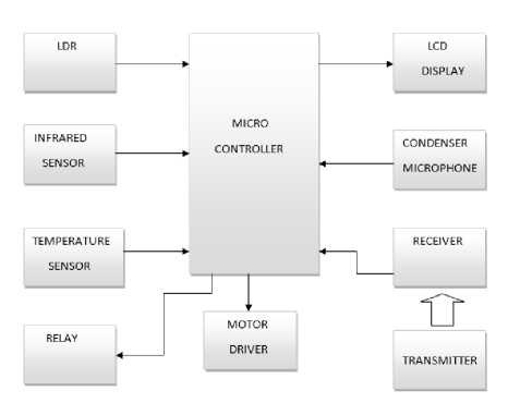
Fig. 6: Hardware Block Diagram
The sixth mode is the pits avoider mode. The same system can be installed in the cars to avoid the pits and trenches. This mode is useful in hilly areas where most of the accidents occur due to ditches on the roads. Infrared (IR) sensors are used in this mode for
A light dependent resistor (LDR) is a special type of resistor whose resistance decreases when incident light intensity increases. It can also be called as a photo resistor made of high resistance semiconductor. It is widely used in embedded applications like camera exposure control, auto slide focus, colorimetric test equipment and automatic headlight dimmer.
-
3.2 Infrared Sensors
-
3.3 Temperature Sensor
-
3.4 Relay
Infrared (IR) sensor consists of transmitter and receiver led. Transmitter led transmits the infrared rays continuously and these rays get reflected when an object comes and received by receiver led. Infrared sensors are used in IR imaging devices, gas analyser, flame monitors and radiation thermometers.
Bridge Rectifier Voltage Regulator
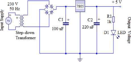
Fig. 7: Power supply schematic
The LM35 is a precision IC temperature sensor, whose output voltage is proportional to the temperature in Celsius. LM35 sensor is interfaced with the microcontroller to show the room temperature.
A relay is an electrically operated switch consisting of a coil which is energised by the low-voltage circuit and one or more sets of switch contacts which are connected to the high-voltage circuit.
-
3.5 Motor Driver
-
3.6 Liquid Crystal Display
-
3.7 Condenser Microphone
Motor driver IC is used to control motors through a microcontroller. L293D IC is used as a motor driver IC. It provides different logic to control the direction of the motor. It is assembled in a 16 lead plastic package, which has 4 center pins connected together.
A Liquid Crystal Display is a display which uses the light modulating properties of liquid crystals. It is used to display alphanumeric characters and symbols. 16X2 LCD has been used in the modeled system to display the information regarding the modes of operation.
A condenser microphone is a transducer, which converts sound into an electrical signal. Condenser microphones are used in many applications such as telephones, hearing aids, tape recorders, in television and radio broadcasting and in computers for recording voice, and speech recognition.
-
IV. Power Supply
The microcontroller uses a +5V w.r.t ground supply which is developed as shown in Fig.7:
Five volts power supply is needed for the microcontroller and it must be purely dc. The circuit consists of a step down transformer which converts 230 V ac to 12 V ac. This 12V ac is given to the bridge rectifier, which converts it into 12V dc. 7805 voltage regulator is used ,which converts 12V dc to 5V dc and this output is then given to the microcontroller for its operation.
-
V. Circuit Simulation
The simulation of the circuit has been done on Proteus Professional v 8.0 software package. There are total 33 I/O ports in the microcontroller out of which six ports are analog ports. 16X2 LCD is used in the system and it is connected to the PORTD of the microcontroller. The simulation of the circuit is shown below in Fig.8:
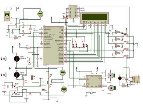
Fig. 8: Simulation Circuit
Table 2: Logic Table showing different modes of Operation
|
S.no |
RB2 |
RB3 |
RB4 |
RB5 |
Model of Operation |
|
1 |
0 |
0 |
1 |
1 |
ST |
|
2 |
1 |
1 |
1 |
1 |
TM |
|
3 |
1 |
0 |
0 |
0 |
SA |
|
4 |
1 |
0 |
1 |
0 |
VM |
|
5 |
0 |
1 |
0 |
1 |
DA |
|
6 |
1 |
1 |
0 |
0 |
PA |
|
7 |
0 |
1 |
1 |
0 |
OA |
Table.2 shows the logic table for triggering different modes by the transmitter. By giving a 4-bit logic, any mode can be triggered to run a specific application.
Register-transfer level (RTL) is the abstraction of a design in which synchronous digital circuits are modeled in terms of the flow of digital signals between hardware registers and the logical operations performed on those signals. Fig.9 shows the RTL design of the modeled system.
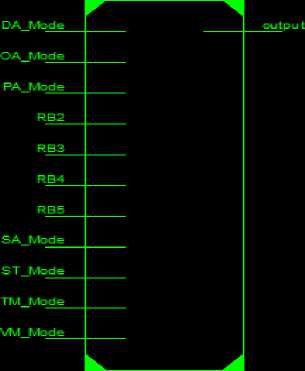
The technology diagram of the system is shown in Fig.10 in which the implementation of the transmitter logic is done by realizing different gates and multiplexers. By selecting an appropriate logic, output can be the required mode. The software of the system is written in embedded C language.
Fig.11 shows the testbench waveform of the system which has been obtained through Xilinx software v10.1. The simulation has been done for 1000 ns and the various mode triggering is shown when appropriate logic is given by the transmitter.
multi functional bot
multi functional bot
Fig. 9: RTL of the System
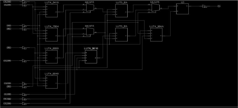
Fig. 10: Technology Diagram
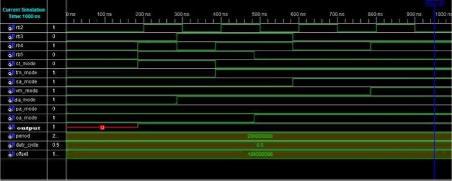
Fig. 11: Testbench waveform
The multi functional bot system is extensively tested in the lab and the real images are shown in Fig.12. All the modes have been checked and the system is working properly under normal conditions.
-
VI. Results
The system is extensively tested and all the modes are running in good agreement with the simulation results. The bot is tested using Xilinx software v10.1
and the relations obtained through MATLAB are validated with the actual results. The system has been designed to perform the above mentioned applications. The transmitter is used to trigger the different modes wirelessly. The logic applied in the transmitter to trigger modes has been given in the Table.2. Realization of the logic has also been done through gates and shown in Fig.10. In Fig.11 the test bench waveform of the system is shown. A particular mode is triggered when an appropriate logic from the transmitter is applied.
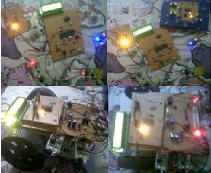
Fig. 12: Versatile Bot System Images
-
VII. Conclusions and Future Scope
The system proposed here is better than the conventional systems which are having one or two modes only. The present system has seven modes and all the modes are working properly. Each mode has a specific application which can be triggered by the transmitter. This study can be extended in terms of area and power at layout and characteristic level by using advanced VLSI applications.
References Performance Analysis of Multi Functional Bot System Design Using Microcontroller
- P. Lamon "The solero rover. 3D-position tracking & control for all-terrain robots", Adv. Robot., vol. 43, pp.7 -19, 2008.
- S.Yasunobu and Y. Murai, "Predictive fuzzy control and parking control," in Proc. of International Conference on American Control, Vol. 3, June 21-23, pp. 2277-2281 ,1995.
- Vaibhav Bhatia and Pawan Whig, " A Secured Dual Tone Multifrequency Based Smart Elevator Control System," International Journal of Research in Engineering and Advanced Technology,Vol. 1, Issue 4, Aug-Sept 2013.
- T.-H Hsu, J.-F. Liu, P.-N Yu, W.-S. Lee, and J.-S. Hsu, "Development of an automatic parking system for vehicle," in Proc. of the International Conference on the IEEE Vehicle Power and Propulsion, Sept. 3-5 Harbin, China, pp. 1-6, 2008.
- R. Mukaro and X.F. Carelse, "A serial communication program for accessing a microcontroller-based data acquisition system", Comput. Geosci., vol. 23, no. 9, pp.1027 -1032, 1997.
- C. Mehta, J. Soni, C. Patel, "Microcontroller based multi-storey parking," in Proc. of Nirma University International Conference on Engineering (NUiCONE), Dec. 08-10, pp. 1-4, 2011.
- J.R. Yang and J. T. Lue "A microcomputer-based programmable Temperature Controller", IEEE. Trans. Instrum. Meas., vol. IM-36, no. l, pp.87 -91 ,1987.
- B. Shamah , M. D. Wagner , S. Moorehead , J. Teza, D. Wettergreen and W. L. Whittaker "Steering and control of a passively articulated robot", presented at the SPIE Sensor Fusion and Decentralized Control in Robotic Systems IV, Oct. 2001.
- L.E. Ray , J. H. Lever , A. D. Streeter and A. D. Price "Design and power management of a solar-powered cool robot for polar instrument networks", J. Field Robot., vol. 24, no. 7, pp.581 -599, 2007.
- A.Sinha, A.Karmakar, K.Maiti, P.Halder, "Re-configurable Parallel Architecture for Signal/Image Processing Applications", Proc. Embedded Systems Conference, Stuttgart, Germany, October 9th-11 th ,2001.
