Performance analysis of NLM interleaving scheme for CPM OFDM system

Author: Gayatri Gupta, Aasheesh Shukla
Journal: International Journal of Wireless and Microwave Technologies @ijwmt
Article in issue: 1 Vol.9, 2019.
Free access
A New Logistic Map interleaving is the most common method for continuous phase modulation based orthogonal frequency division multiplexing (CPM-OFDM) system over a fading channel. The selection of a "good" interleaver having to express in order that the interleavers are weakly correlated. Interleaver doesn’t involve massive memory to reserve it and a massive bandwidth to communicate in the midst of the transmitter and the receiver, and need to be simple to produce. An efficient chaotic maps randomization (CMR) generates scrambled uncorrelated randomized data can greatly improved the performance of CPM-OFDM system and improved symbol error rate (SER) could be attained. In this study, advise a new one-dimensional chaotic map, the "New Logistic Map (NLM)". Encryption is carried out with logistic map even as a chaotic logistic map interleaving process is used to boost the immunity to noise and fading in communication channel. Furthermore, a evaluation between NLM interleaving and random interleaving is performed in terms of bit error rate(BER).Simulation results shows that the data transmission over wireless channel using propose NLM interleaving is more immune to fading and noise and get better the performance of CPM-OFDM system.
Chaotic system, Logistic map, Interleaver, OFDM, constant envelope, Random Interleaving
Short address: https://sciup.org/15016956
IDR: 15016956 | DOI: 10.5815/ijwmt.2019.01.02
Text of the scientific article Performance analysis of NLM interleaving scheme for CPM OFDM system
OFDM is taken an account of the most effective multicarrier transmission (MCT) techniques in favour of mobile communications, as it gives a massive immunity in order to multipath fading as well as impulsive noise, also removes the requirement for complex equalizers[2].
In spite of all of the advantages, there are some drawbacks of OFDM. The major limitations of OFDM systems are high peak average power ratio (PAPR). As the number of subcarriers increases, PAPR of OFDM signals increases.
Signals are transmitted over non-linear power amplifier because of high PAPR, harsh signal distortion will happen. As a result, power backoff with linear power amplifier is required for OFDM systems [3].The system undergo from spectral broadening, intermodulation distortion, without sufficient power backoff , and, therefore, performance degradation. This issue might be decreased by increasing the backoff, but this cause to happen decreased power amplifier (PA) efficiency. Due to limited power resources this is particularly an issue for mobile battery-powered devices. Minimizing its effect fit in concern to both commercial and military applications [4]
Several approach have already been planned to work out the PAPR difficulty like clipping and filtering, Tone Injection (TI), coding, Tone Reservation, and also multiple signal representation techniques, for example the Partial Transmit Sequence (PTS), the interleaving approach, and the selective mapping. These approaches are used to solve the PAPR problems and increase the signal transmitted power, computational complexity and achieve better bit error rate (BER). An another method to justifying the PAPR difficulty is based on signal transformations [5]
In cellular communication, the idea of Continuous Phase Modulation is used due to it has a constant envelope (CE) that has essential for effective power transmission and have the capability to take advantage of the diversity of multipath channel resulting in upgrading the bit error rate. The benefit of the Phase Modulator (PM) transforms one the transformed signal has the minimum attainable PAPR (i.e. 0 dB). These signals may well be amplified along nominal power backoff, and that: 1) boost the effectiveness of power amplifier, along with 2) probably increases scheme range, therefore, additional signal power is propagated toward the channel. Phase modulation is drawing attention for wireless telecommunications due to the CE of your generated signals, and that’s needed for efficient power transmitters, and has a capacity to take advantage of the diversity of your multi-path channel, whichever is desirable to recover the Bit Error Rate performance.
In the era of Internet growing and multimedia for example video, audio signals and image are simply transmitted from a service provider to a consumer, this offer an immense payoff for enhancement of multimedia, E-commerce as well as entertainment industry that depend on the Internet. As consequences surveillance plays an important part in the interest of content security to save multimedia content from an unauthorized user. In the earlier days, encryption had been changed into a big tool for private media content. Ever since the 1990s, a growing consideration had been dedicated to the use of chaotic functions to apply the procedure for encryption. A number of researchers have observed that correlation among chaos and cryptography [6]
A new interleaving proposal is proposed in this paper. In this system a chaotic map randomization for the Continuous Phase Modulation-OFDM scheme. The projected method is utilize for efficient data transmission over fading channel with OFDM and improve the bandwidth efficiency. An interesting comparative analysis between propose method and random interleaving.
The paper is organized as follows. CPM-OFDM system model is described in Section II. Random interleaving and the proposed new logistic interleaving methods are described in section III. The equalizer designs explain in section IV. In section V Phase demodulator structure. In Section VI spectral efficiency of the Continuous Phase Modulation systems. Computer simulation results in Section VII. Finally, the conclusion in Section VIII.
-
2. Cpm-ofdm Model
Another way to deal with the PAPR issue is depending on transformations of the signal. In this method, before amplification, a signal transformation has performed after that an inverse transformation is performed just before to demodulation at the receiver.
Here [1], a PM transformation was regarded as to produce signals with Continuous Phase Modulation. This system is suitable in favor of wireless communications due to the constant envelope (CE) of your generated signals (i.e. 0dB PAPR), that’s desired for power resourceful transmitters, which had to get better the Bit Error Rate performance. CPM-OFDM model shares some of the similar functional blocks by means of a conventional OFDM structure. Then the present OFDM structure ready to given that an additional CPM-OFDM approach, simply.
Figure:1. Show the block diagram of the CPM-OFDM system Let X ( k ) indicate the data symbols after mapping, x( n ) be the NDFT-points IDFT of data symbols X(k). For the duration each T-seconds, blocks interval, the time samples x ( n ) is generated sequence from OFDM passes through a PM to attain 0dB PAPR sequences s(n), n=0,1......NDFT — 1 . The CE sequence which is offered by PM s(n) = exp(jCx(n)), wherever C denote scaling constant. Later that PM, a chaotic interleaving is applied and that rearrange the phase modulated symbols in keeping with randomization approach explain in section III. The obtained sequence s; (n) is used to refer to chaotic interleaving. Then, N cyclic prefix is added between blocks to alleviate inter-block interference effect. The O/P sequences are s; (n), n = —Ng ... 0 ...,. NDFT — 1.
The continuous-time signal s (t) is propagated at the output (O/P) of the digital-to-analog converter. This Continuous Phase Modulation signal could be expressed as follows in according to [7-8]
s(t) = Ae^^m = лИ2^'”-) +'', Ts < t < T (1)
Where A signify signal amplitude,
-
6 denote arbitrary phase offset utilize to attain CPM,
Ts denote the guard period, h denote modulation index,
T denote block period and
m(t) denote real-valued OFDM message signal comprised of K subcarriers given as [1]
m(t) = CnT«=iIkqk(t) (2)
Where Ik are M-ary the real-valued the Pulse amplitude modulation data symbols,Ik £ {±1,±2,...,±(M — 1)}, M is the constellation points, the orthogonal subcarriers are qk(t), the normalization constant is Cn. The real-valued data symbol, Ik could be written as
f ^{X(k)}, k < K/2
k l—3{X(k — K/2)}, k>K/2
Where as ^^(k)} are the real and 3{X(k)} imaginary part of {X(k)}, respectively, qk(t)denote orthogonal subcarriers can be written as follows:
(f2^kt\ , _ К qk(t) =
cos(—), k<
510(2^/22), k>|
Using equation (3), (4), and (2) can be rewritten as:
m(t) = Cn
ZK=1K[X(k)}cosp^)-^Kk=K/2+i3{X(k)}sin(2M2))
The transmit signal st (t) pass throughout the multi path channel. The channel impulse response (CIR) for L discrete path is expressed as:
Ш^Е-МЖ-т) (6)
where h(l) is the channel gain,
Tl is the delay of the 1th path
The continuous-time received signal can be written as:
'iU) = Е|=о ^(Z)s(t - Ti) + n^t) (7)
Where n(t) is a complex AGWN with single-sided power spectral density No.
r;(i) = E^1 h(n)s(i - n) + n(i)
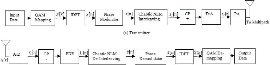
Fig.1. The CPM-OFDM system model with chaotic interleaving
The received signal r;(i) is transformed into the frequency domain by using the NDFT-point Discrete Fourier Transform (DFT), defining NDFT = JK.
-
3. Interleaving Mechanism
Fading and other channel errors like burst errors affect the data transmitted all the way through the wireless channel. To offer a protection to the data transmitted throughout wireless channels numerous error correction codes has previously been used that is valuable corrective random errors because of the wireless channels and the drawbacks of wireless channel are that one they causes bursty channel errors. The burst error can be known as a contiguous sequence of error symbols where it can define either in one dimensional (1-D) form or in multi dimensional form [9]. Interleaving is a process to rearranging input symbols based on predefined rule such that consecutive data are divided between different blocks. On the receiver end, the original sequences are restored in accordance to reverse rule by the de-interleaver. Interleaving is used to alleviate the effect of burst errors and multiple access interference (MAI) at the receiver. Burst error means excessive error exists in a single codeword. Therefore, interleaving is process which is used to randomize the burst of errors which are because of multipath fading environment and also enhance the behaviour of the error correcting codes [10]
There exist two most popular of interleaver, namely random and chaotic interleaver. First we explain the basics of random interleaver and then we review the proposed New Logistic map interleaving mechanism.
-
A. Random Interleaving Mechanism
Random Interleavers are use to generate independently and randomly. By using random interleaver, the different user’s data scramble by means of the different pattern. Scrambling patterns of the user data are generated randomly. By reason of the scrambling of data, randomized channel burst error at the receiver side. By using permuter indices the arriving data is rearranged. For a specified memory address a device generates pseudo-random permutation, such device can be referred as a permuter. A lot of memory required for the reason of user separation at the transmitter and receiver ends for the use of their storage space if random interleaver is utilized. For broadcast of all these interleaver, a large quantity of bandwidth will be consumed. Also, computational complexity automatically boost at receiver ends. Usually, the interleaving techniques are defined as an efficient anti-burst error technique. The random interleaving method cannot fight the 2D bursts of errors. The base station has to consume an enormous quantity of memory on the way to save the random patterns of interleaved that may create severe interest of storage in case of the massive user [11]. But some limiting factors motivate for further research. These limiting factors are computational complexity, the memory requirement for the storage of the interleaving pattern and detection at the receiver.
-
B. Proposed Chaotic logistic Interleaving Mechanism
In prior subsection, the random interleaver isn’t proficient with two-dimensional bursts error. Consequently, there is a requirement for advanced interleaver for this assignment. The signals are rearranged in a twodimensional format, after Phase Modulation and then New chaotic Logistic map (NLM) used to randomized separately. By using chaotic randomization step that generates permuted sequences with lower correlation among their samples. Furthermore the NLM includes a quantity of encryption to the transmitted signal.
-
(a) Chaotic system
-
(b) New Logistic Map (NLM)
The logistic population model is very popular to understand chaos. The New logistic map is extremely easy statistical model generally utilized to explain the biological population’s growth. Due to its statistical ease, this representation is still helpful in chaos theory in addition to demand of chaos in cryptography [12]. Lately, the logistic MAP has been obtained heightened attention because of its significance for generating a pseudorandom helpful numbers in several forms of application, similar to numerical analysis, simulation, sampling, spread spectrum, synchronization, etc.
Definition 1: The logistic map is given as:
f^n ) = хи +1
= r xn(1 -xn)
where, r is growth rate of population and an important parameter to discuss. Here parameter r is elaborated for different value ranges.
For the range 0 ≤ r ≤ 4.
Proposition: For the above range logistic map sends [0, 1] to itself.
Proposition: For the value of r < 1, fixed and stable point is 0. For the value r > 1 it is unstable. One more point is stable i.e. x = 1 – (1/r), but only for 0 < r < 3 and unstable for r > 3.
Proof: If we solve the equation rx (1-x) = x, the fixed point yields x1 = 0 and x2 = 1 — (1/r) and from the derivative of equation i.e. f’(x) = r (1- 2x) we get f’(0) = r. Hence 0 is stable point for the specified range.
Similarly second point is also stable for above said range.
Proposition: The logistic map has 2 cycles for r > 3 and stable if . 61+< r
Proof: In 2 cycle, logistic map has set of points such that u ^ v £ [0,1] and f (u ) = v and f ( v ) = u and hence f 2( u ) = u and f 2( v ) = v . Now solving the equation f 2( x ) = r 2 u (1- x )[1– rx (1– x )] = x yields four solutions and these solutions proves that the map forms 2-cycles if r > 3.
Now another interesting property is yet to be discussed i.e. sensitivity on initial conditions, which is a much needed requirement for a spread spectrum system to be chaotic
Definition : Let aObe initial condition and consider the orbit of a nearly point a0 + 60 where 60 is very small. Let is the separation in two orbits after n iterations. If, |0n| = |0O |епЛ then X is called the Liapunov exponent. A positive value of it shows dependency on initial condition.
Above discussion shows that as the value of r increases, the stability coefficients of the fixed points decreases and at r = 3, a stable 2-cycle formed. So this value of r is popularly known as period doubling bifurcation. For higher values of r , again 2-cycle has also become unstable but simultaneously a stable 4-cycle started at r = 3.4494897.
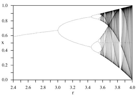
Fig.2. Bifurcation diagram[13]
In Fig.2, the entire discussions can be pictorially depicted that for r < 4 an orbit eventually converges to the stable fixed point. In Fig.1, the situation is completely different at r = 4 i.e. it may be considered as chaotic. At this value of r the stable point becomes unstable. In spread spectrum communication chaos gives plenty of advantages in addition a variety of opportunities for farther improvement. The nature of chaotic system are sensitivity to initial conditions and random nature might be helpful to produce high amount of uncorrelated, random-like, yet deterministic and reproducible signals or sequences. Several For the generation of chaotic sequences chaotic maps are helpful and these sequences could be utilized at the interleaving sequences and p-n codes [13]
-
4. Equalizer Design
Frequency domain equalizer is discussed in this section. FDE depend upon the subsistence of a Cyclic Prefix guard interval in the midst of consecutive data blocks. The FDE benefits is the comparatively low complexity. On the other hand, the Frequency Domain Equalizers (FDE) requires a Cyclic Prefix overhead. Let the O/P of FDE is Si as shown in Figure.3
^(п) = — XVD-Fr1 X(m)R1(m)ej2nmn/VlF>FT m 0
where n = 0,1,...... N DFT — 1 ,R1(m) denote the DFT of r1(t),X(m) denotes the equalizer correction terms, that is computed in accordance with the type of the Frequency Domain Equalizer. In this study, three types of Frequency Domain Equalizer as follows:
-
1) The zero-forcing (ZF) equalizer:
X (m) = ——- v H(m)
-
2) Minimum mean square error (MMSE) equalizer:
X (m) =
H * (m) |H(m)| 2 + (E6/V o )-1
-
3) The regularized zero forcing (RZF) equalizer:
X(m) =
H*(m) |H(m)|2+^
-
5. Phase Modulator
Where β denote regularization parameter RZF equalizer explained in (13) and (.)* represent complex conjugate avoid the issue associate by means of the Minimum mean square error equalizer, for instance, measurement of your noise power and signal power, that isn’t accessible just before equalization. Furthermore, the Regularized Zero Forcing (ZF) equalizer avoids the noise development due to the ZF equalizer which is introduced by means of β regularization parameter interested in the equalization process.
In defining the Zero Forcing Frequency Domain Equalizer(ZF) as given in (11), shows the completely reverse outcome of the channel without the presence of noise because in case of noise it will suffer from noise enhancement.In contrast, the Minimum Mean Square Error equalizer in (12) that notices the signal-to-noise ratio creation best possible trade-off in the middle of the noise enhancement and channel inversion.
To reduce the error stuck in the midst of the estimated signal, the equalizer coefficients are selected, s(n) and § 1 (n) is the original signal.
Д= E|S1(n) — s(n)|2 (14)
The FDE signals are followed by chaotic deinterleaved and also applied to the phase demodulator to attain the estimated datax(n) .
The design of the phase modulator (PM) is talked about in this part. Figure.3 shows the phase demodulator block diagram. The performance of the phase demodulator is improved by using the impulse response filter as it rejects the out-of-band noise. With the help of the windowing technique, the filter is designed. If filter response has a length L f and frequency f n 0r ( 0 <1) is the normalized cut-off frequency given below:
SOO =
sin(2’Tf nor (n—4“))
-^-r- ,
0 < n < Lf — 1
In Eq. (15), if n = L f — 1/2, g(n) = 2nfnor /я. In our study fn0r = 0.2 and L f = 11 are used. After getting a filtered signal, use phase extraction step for the calculation of the phase of its argument. At last the signal we get is unaffected by phase offset, so that the receiver is insensitive to this and minimizes the effect of phase ambiguities due to channel and memory term. PM is followed up matched filters to get soft estimated data symbol 'x(k).
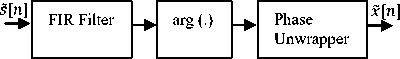
Fig.3. Phase Modulator[7]
-
6. Multipath Diversity and Spectral Efficiency of Cpm Signal
The spectral efficiency are essential qualities metrical for a modulation system while it quantifies what percentage of information bits/second could be weighted per unit of the accessible bandwidth. To get estimated signal spectral efficiency, bandwidth must be determined. The Continuous Phase Modulation signal describe in Eq. (1), Using Taylor expansion when θ = 0, can be rewritten as:
s(O =^e7'2"ta(£) = Л£”=0р2^]хп(0 = л[1+;2яШ0-(^^(O—V^^^tH-"] (16)
The frequencies of subcarriers are centred at Hz, i = 1 , 2 … K/ 2.The message signal x (t) have an effective double-side bandwidth. It is defined as W = K/T Hz. In accordance to Eq. (4.16), Only the first two terms of the summation are consider, W is the bandwidth of s ( t ). Depending upon the modulation index rate, the resourceful bandwidth could be larger than W [14]
BW = max (2πh, 1) W Hz
As given away in Eq. (17), the bandwidth of signal grows by way of 2 πh that minimize spectral efficiency. In view of the fact that the bit rate is R = K (log2 M )/ T bps, the Continuous Phase Modulation signal spectral efficiency η, can be written as:
R
л = —
' BW
log 2 M тах(2лк,1)
Bps/Hz
With the help of two parameters, the spectral efficiency of the Continuous Phase Modulation signal is controlled by M and 2 πh . Conversely OFDM signal has spectral efficiency is log2 M , that depends only on M . The CPM signal does not provide frequency spreading for the higher-order terms. As a result, the signal of Continuous Phase Modulation does not have the potential to utilize the frequency diversity of the channel.
-
7. Simulation Results and Discussion
In this Section, a new technique which is based on Chaotic New Logistic Map (NLM) is proposed for timing offset estimation in an OFDM system. The proposed method used a NLM interleaving scheme for CPM-OFDM system. The simulation results show that chaotic NLM interleaving with CPM-OFDM gives a good trade-off stuck between bandwidth efficiency and performance, while it attain an efficient consumption of the frequency diversity and sustain the high bandwidth. A chaotic New Logistic Map (NLM) interleaving scheme proposed for the CPM-OFDM system. On comparing simulation results as shown in Figure 4 to 7, for the different data length, it is clear that the proposed scheme improves BER performance more effectively than both CPM-OFDM and Chaotic Interleaving CPM OFDM system. After analysis of complete results, I have been observed that Chaotic NLM Interleaving is best suitable technique for upcoming 5G communication and future radio communication So we can say that NLM interleaving improves the spectral efficiency when utilize with CPM-OFDM system, it gives an efficient usage of the frequency diversity and maintain the high bandwidth. When a number of users are large and at high SNR, we find better results. It is more efficient with the higher number of users.
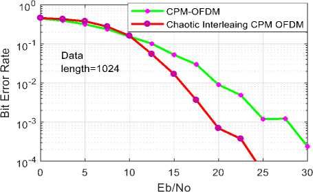
Fig.4. BER vs. SNR comparison of CPM-OFDM and chaotic interleaving CPM-OFDM for Data length=1024
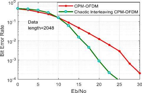
Fig.5. BER vs. SNR comparison of CPM-OFDM and chaotic interleaving CPM-OFDM for Data length=2048
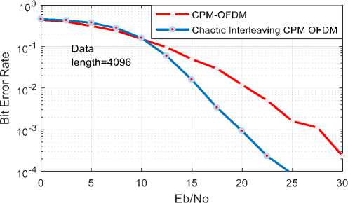
Fig.6. BER vs. SNR comparison of CPM-OFDM system and Chaotic Interleaving CPM-OFDM for Data length=4096
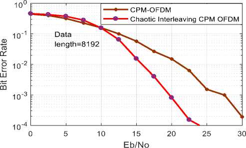
Fig.7. BER vs. SNR comparison CPM-OFDM and chaotic interleaving CPM-OFDM for Data length=8192
-
8. Conclusions
A new efficient technique which is based on Chaotic New Logistic Map (NLM) is proposed for timing offset estimation in an OFDM system. The proposed scheme improved BER more effectively than CPM-OFDM. The simulation results show that chaotic NLM interleaving with CPM-OFDM gives a good trade-off stuck between bandwidth efficiency and performance, while it attain an efficient consumption of the frequency diversity and sustain the high bandwidth .
References Performance analysis of NLM interleaving scheme for CPM OFDM system
- Hassan, Emad. Multi-carrier communication systems with examples in MATLAB®: A new perspective. CRC Press, 2016.
- Nair, Anish, and Kamran Kiasaleh. "Chaotic circle map interleaver for OFDM." Computing, Networking and Communications (ICNC), 2016 International Conference on. IEEE, 2016.
- Tsai, Yingming, Goudong Zhang, and J-L. Pan. "Orthogonal frequency division multiplexing with phase modulation and constant envelope design." Military Communications Conference, 2005. MILCOM 2005. IEEE. IEEE, 2005.
- Thompson, Steve C., et al. "Constant envelope OFDM." IEEE transactions on communications 56.8 (2008).
- Ramadan, Khaled, et al. "Continuous phase modulation for digital video broadcasting." International Journal of Computer Applications 81.1 (2013).
- Kasem, Hossam M., Mohamed E. Nasr, and Amr H. Hussein. "A High Fidelity OFDM Image Communication System with Chaotic Maps."
- Hassan, Emad S., et al. "New interleaving scheme for CE-OFDM systems using chaotic maps." Wireless and Optical Communications Networks, 2009. WOCN'09. IFIP International Conference on. IEEE, 2009.
- Hassan, Emad S., et al. "Chaotic interleaving scheme for single-and multi-carrier modulation techniques implementing continuous phase modulation." Journal of the Franklin Institute350.4 (2013): 770-789.
- Jindal, Shikha, and Diwakar Agarwal. "Performance evaluation of image transmission over MC-CDMA system using two interleaving schemes." Advances in Computing, Communications and Informatics (ICACCI, 2014 International Conference on. IEEE, 2014.
- Shaikh, Quanitah, Pallavi Patil, and Afreenzehra Sayed. "Improvement in BER Performance of OFDM System using Interleaver." International Journal of Science, Engineering and Technology Research (IJSETR), Volume 4, Issue 2, February 2015.
- Kumari, Neelam, and A. K. Singh. "IDMA Technology and Comparison survey of Interleavers." International Journal of Scientific and Research Publications 3.9 (2013).
- Patidar, Vinod, Krishan K. Sud, and Narendra K. Pareek. "A pseudo random bit generator based on chaotic logistic map and its statistical testing." Informatica 33.4 (2009).
- Aasheesh, Shukla, and Vinay Kumar Deolia. "PERFORMANCE ANALYSIS OF CHAOS BASED INTERLEAVER IN IDMA SYSTEM." ICTACT Journal on Communication Technology 7.4 (2016).
- Hassan, EMAD S. "Performance enhancement of continuous-phase modulation based OFDM systems using chaotic interleaving." WSEAS transactions on systems 12.1 (2013): 1-10.
