Performance Analysis of VBLAST Based MIMO OFDM System in Vehicular Channel

Author: Samarendra Nath Sur, Soumyasree Bera, Arun Kumar Singh, Rabindranath Bera, B.Maji
Journal: International Journal of Intelligent Systems and Applications(IJISA) @ijisa
Article in issue: 12 vol.6, 2014.
Free access
Vehicular communication is emerging as an important ingredient for successful implement of Intelligent Transportation Systems(ITS). But the development of suitable communications systems plays an important role in mobility condition. The desired system should support dynamic wireless exchange of data between nearby vehicles or road side infrastructure. In this regards multiple input and multiple output (MIMO) orthogonal frequency domain multiplexing (OFDM) system is possibly the best solution. This paper deals with the performance analysis of the MIMO OFDM system in Nakagami-m channel with Doppler shift and also partial hardware implementation of baseband signal processing.
MIMO, Doppler, OFDM, Nakagami-M Channel, Probability Density Function (PDF)
Short address: https://sciup.org/15010639
IDR: 15010639
Text of the scientific article Performance Analysis of VBLAST Based MIMO OFDM System in Vehicular Channel
Published Online November 2014 in MECS
ITS consist of several combinations of communication, computer and control technology developed [1] and its main goal is to improve system performance, transport safety, efficiency, productivity, and level of service, environmental impacts, energy consumption, and mobility [2]. The functionality of the ITS is stretch over vast transportation infrastructure of highways, streets, bridges, tunnels, railways, port and airport infrastructure, as well as to a growing number of vehicles, including cars, buses, trucks and trains [1, 3].
Lots of initiative have been taken to introduce ITS. Large scale national ITS projects began in Europe, The US and Japan in the mid-1980s. The EU’ (European Union) Safety initiative [4], announced in November 2002, aims to halve the number of annual traffic accident fatalities in the EU by 2010 and aim for “zero traffic fatalities” by 2020. The United States’ ITS Ten-Year Plan [5], announced in January 2002, talks about achieving a 15% reduction in the number of annual traffic fatalities by 2011. Europe takes a prime role in regional and international ITS standards activities to advance its ITS technology in the world market. The European Committee for Standardization (CEN) put focused on ITS standards issues. Many ITS standards items are developed in parallel by ISO/TC204 and CEN/TC278 [6]. Japan has been very successful in translating its strengths in electronics technology into successful ITS.
Various forms of wireless communications technologies have been proposed for intelligent transportation systems. Such as Short- range communications using IEEE 802.11 protocols, and Dedicated Short Range Communications (DSRC) standard. From the wireless LAN family, 802.11p/WAVE (Wireless Access for a Vehicular Environments) is developed to provide support in the 5.9 GHz band which has been allocated for ITS in The USA and is under deliberation in Europe and Australia; and a 5.8 GHz allocation in Japan [7]. The aim of CALM is to provide wide area communications to support ITS applications that work equally well on a variety of different network platforms, including Second Generation (2G) mobile (e.g., GSM/GPRS), 3G (IMT-2000 e.g., W-CDMA/CDMA 1x EV-DO) 4G (IMT-Advanced), as well as satellite, microwave, millimetre wave, infrared, WiMAX and WiFi [7]. Recently, two wireless communication schemes, which can be used efficiently to combat with multi-path fading, are extensively investigated around the world. One is MIMO technology and other is the OFDM technology. As an outcome, a combined system, MIMO-OFDM, can be used for fourth-generation (4G) mobile cellular wireless system.
From the point of view of the vehicular communication system, mobility may be the challenge or major problems for the next generation communication. In this context 4G LTE is now operational at different part of the world with 4x4 antenna configuration. Later LTE-A research works are initiated all over the world to address high data rate with high antenna configuration (max. 8x8) under full vehicular mobility condition and is optimized for low speeds like 0-15 kmph but it supports also speeds upto 350 kmph.
This paper addresses the combined VBLAST-MIMO-OFDM technique with enhanced performance under high mobility condition.
The paper is organized as follows: The overview of VBLAST MIMO and Nakagami-m channel is discussed in Section II. ICI analysis and BER calculation are presented in Section III and IV respectively. Simulation results and hardware implementation are presented in Section V and this paper is summarized in Section VI.
-
II. Overview On V-Blast-Mimo System And Nakagami Channel
-
A. VBLAST MIMO OFDM System Model
We consider a V-BLAST MIMO OFDM system with multiple transmitter and receiver antennas with perfect channel state information (CSI) at the receiver. Figure below shows a basic block diagram of a VBLAST MIMO OFDM system.
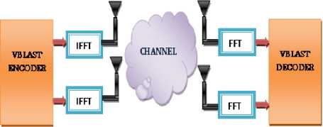
Fig. 1. VBLAST-OFDM system model
At the transmitter incoming bits are mapped using MPSK or MQAM, the layered using VBLAST algorithm. This layered data then feed to the OFDM modulation block. The OFDM signal for each antenna is obtained by applying the inverse Fast Fourier transform (IFFT) on the transmitter side. A cyclic prefix (CP) is inserted in front of the OFDM symbol at the final step of OFDM modulation block. Cyclic prefix is used to reduce the inter symbol interference (ISI). At the receiver side Fast Fourier transform (FFT) is applied after removing the CPs. Then Channel estimation using VBLAST zero forcing (ZF) detection for each OFDM sub-carrier followed by demodulation.
-
B. Nakagami-m Channel
The Nakagami-m model serves as a channel model in the highway scenario and is considered as a suitable probabilistic vehicular channel model. However, the transmitter and receiver are moving at high speed in V2V environments. This causes different fading statistics depending on the existence of a line-of-sight (LOS). The m parameter is inversely proportional to distance since the chance of having LOS decreases as distance increases due to turn or intersections on the road.
The PDF of the instantaneous SNR γ for the Nakagami m distribution is [8, 9, 10]:
P , ( y ) = -1- f m 1 ” Y m - 1 exp f- mt ) , yS 0 (1)
r (m) ( y ) V Y )
PDF of Nakagami-m Channel
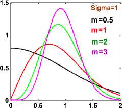
Fig. 2a. PDF of Nakagami channel
CDF of Nakagami-m Channel
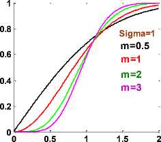
Fig. 2b. CDF of Nakagami channel
Rayleigh fading conditions, i.e. no line-of-sight exists, can be obtained through Nakagami by setting m = 1. Higher values of m can be used for approximating Rician distributed channel conditions where a line-of-sight path exists, while for m <1, the channel conditions are worse than the Rayleigh distribution.
-
III. ICI Analysis
An OFDM system basically consists of a parallel transmission [11-14]. Each parallel data is mapped with M-ary PSK/ M-QAM digital modulation scheme and, then, those data are modulated by an IFFT on N-parallel subcarriers. After adding cyclic prefix, the parallel data streams are converted to serial one and then the complete OFDM symbol is transmitted over a discrete-time channel. At the receiver, again the serial data stream is converted to parallel one. After the removal of cyclic prefix, the data are retrieved by a FFT and, then, demapped with corresponding scheme to obtain the estimated data.
In an OFDM system the transmitted signal can be represented by
x(n) = Yl l>(p)e j2 ” p"/N (2)
N p = 0
where x(n) denotes the nth sample of the OFDM transmitted signal, X(p) denotes the modulated symbol over the pth subcarrier and N is the total number of the subcarriers.
The received signal in time domain after DFT could be written as
Y(p) = N S y(n)e - j2 n pn/ N + G(p) (3)
Nn = 0
Where G(p) denotes an additive white Gaussian noise for the pth subcarrier.
Assuming the channel frequency offset normalized by the subcarrier frequency spacing denotes as ε and discrete time domain OFDM signal y(n) is multiplied by the factor e J 2 n n E / N in (3) to resent the frequency offset.
As in [11], equation (3) can be written as
N - 1
Y(p) = S(0)H(p)X(p) + S S(l - p)H(l)X(l) + N(p) (4) l = 0,l * p
Where p=0,1 -----, N-1.
The ICI coefficient between lih and pih sub-carrier, S(l-p) can be expressed as sin(n(l-p + e))1
S(l - p) =-----'cxplj-fl - -)(l - p + e)]
Nsin(^(l - p + e ))
and S(0) = slnc( e) exp [jn(1 - -1)£]( 6)
-
■ < eN
sin c( )
N
Here, S (0) produces the phase rotation to the modulated symbol for pth subcarrier.
The first term in equation (4) represent the carrier component and the average power on the pth can be written as
E[C(p)|2] = E[|X(p)H(p)S(0)|2] (7)
The second term represents the ICI component and the average power of it can be written as
E [ n n H ] =
N + e 2 Notr ( H H H ) - 1
+ 4 N 0 n (f D t ) 2 tr ( H H H .) - 1
X ( H H H ) - 1
4 Es n 2( fpt )2
3 Nt where (.) H denotes Hermitian transpose, e is the quantity that measure the channel estimation accuracy , fD represents the doppler shift and tr(.) represents the matrix trace operation.
The SINR per symbol of each stream can be represented as
Y
Es/N0
r
[1 + e2NtEs/No] +
I
Г 4Es n 2(fDt) 3N0
E[|l(p)|2] = E
N - 1
Z S(l - p)H(l)X(l) l = 0,l * p
]
The average SINR for the pth subcarrier can be
represented as
SINR(p) =
E[X(p)H(p)S(0) 2]
E[
N - 1
Z S(l - p)H(l)X(l) l = 0,l * p
]
B. BER calculation for MPSK modulation.
The moment generating function (MGF) [16, 17] of the SNR in Nakagami-m fading is given by to
P y ( s ) = J exp( - S Y ) P y ( Y ) d Y
When SNR is high, the achievable system BER performance in presence of the frequency offset is governed by SINR.
The conditional- error probability (CEP) for MPSK is given by
-
IV. BER Calculation
-
A. The Zero-Forcing Receiver for MIMO Systems
Consider a multi-antenna system with Nt transmit and Nr receive antennas, where Nt < Nr . We assume a Nakagami-m flat fading channel and can be denoted by a Ntx Nr matrix H. The received signal vector r can be represented as r = Hs + n, where Nt symbols s is transmit data symbol vector, n ~ CN(0,N0IN ) is additive white Gaussian noise (AWGN), and IN is an Nx N identity matrix. If we assume the CSI is perfect, the zero forcing estimate of the transmitted symbol vector and can be expressed as given 'r = Wzf(Hs + n), where Wzf = H + = (HHH) - 1HH the weight vector associated to the ZF receiver is.
As in [15], the noise covariance can be represented as
n M
PS (Y) = - J exp n J0
sin2 6
dd
The average symbol error rate in Nakagami channel for positive value of fading depth m is given by
to
Ps =J Ps( y )P y ( Y )d Y
= 1Is
П
0, n
—
v
M,
As in [16], the generalized form of Is can be
expressed as
6 U
I . ( 6tAlc , d ) = J
6 l
sin2 6
c + sin2 6
d6
6 U -O L
-
I С Г ТЕ ""I d-1 1
J --- n + X (c, Ou) Z --------
V C + 1 L 2 V U 'J k = 0 [ 4(c + 1) ] k
f 2k
X Rk
1 kу 1 f 2k ) sin [ 2(k - h)Mc O u) ] ” h Z 0 1 h
I с Г 1 d — 1
Vc+i 2"'"L) л
k - h
1 +
performance is due to the basic fading characteristics of the Nakagami channel, as with the increment of the m value Nakagami fading characteristics changes from one sided Gaussian distribution to Raleigh distribution. As in figure with the change in m values at the high SNR level the system performance improves dramatically with respect to that of in low SNR level.
- k = 0 [ 4(c + 1) ] k
x f 2k L 1k - f 2k ) sin [ 2(k - h)Mc, O l) ] U k J+п h Z 0 1 h J k - h /
Where d is a positive integer and
X (q, O ) = tan 1
c=
^1 ‘in2 ^M )
L=Total no of diversity branches, h= (0, 1, 2 …L) and k=kth signal point with instantaneous SNR у
C. BER calculation for MQAM modulation
The BER of coherent M-QAM with two-dimensional Gray coding over the AWGN channel.
2x2 VBLAST MIMO-OFDM
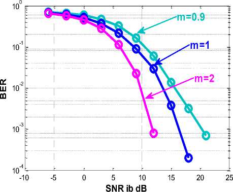
Fig. 3. SNR vs. BER Curves with different m values for Nakagami-m channel.
Рь( у ) = 0.2exp(---3b-)
b 2(M - 1)
The average BER in a slow and fat Nakagami-m fading channel may be derived by averaging the error rates for the AWGN channel over the pdf of the SNR in Nakagami-m fading:
ro
Pb( Y ) = I Pb( Y )xP y ( Y )d Y
-ro
M
= fo.2exp( ^3^) x f m
2( M - 1) Г ( m ) ( y
m f- my 1 (19)
y m 1 exp l ^- I d y (19)
Now after some simplification as in [18], the average BER can be calculated as given below
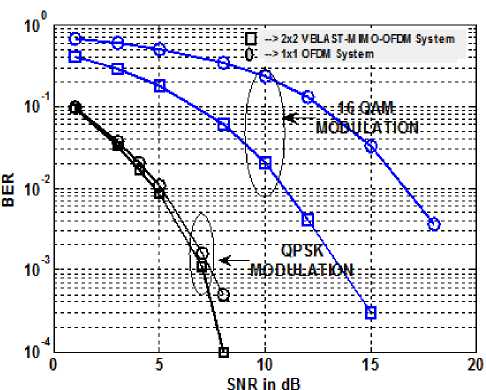
Fig. 4. SNR vs. BER Curves with 200Hz Doppler frequency
Pb( Y ) = 0.2
2m(M - 1)
3 y + 2m(M - 1)
Applying (11) to the BER expression of M-PSK and MQAM for MIMO ZF receiver in equation (15) and (20), we can have the dependence of BER on the Doppler shift.
-
V. Results
-
A. Simulation results
Above figure shows the BER performance of the 2x2 VBLAST OFDM system in Nakagami channel condition. As in figure with the change in m values the performance of the system gets better. This improvement in the BER
Figure 4 represent performance analysis of 2x2 VBLAST MIMO-OFDM system and SISO OFDM system with 200 Hz Doppler frequency. As in figure, with the lower order modulation (here QPSK) the performance gap between the above said two systems is narrow whereas in case of higher order modulation (here QAM) the performance gap between the above said two systems is noticeable. Therefore one can conclude that a combination of MIMO –OFDM is much more effective in case of higher order modulation and in severe channel condition in comparison to SISO OFDM system.
By comparing above curves, it is clear that VBLAST-MIMO-OFDM system provide better performance in comparison to that of VBLAST MIMO system.
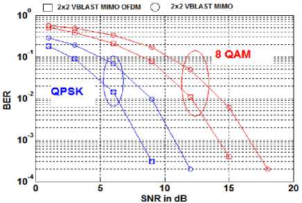
Fig. 5. SNR vs. BER Curves for VBLAST MIMO OFDM and VBLAST MIMO
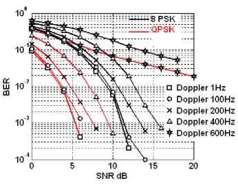
Fig. 6. SNR vs. BER Curves for 2x2 VBLAST MIMO OFDM with different Doppler shifts.
From figures 4 and 6, one can conclude that VBLAST MIMO OFDM have much more tolerance against the Doppler shift and can support the velocity upto 90 KM/hr (400 Hz Doppler and in 2.4 GHz band) and useful for vehicular application.
-
B. Hardware Experimentation:
Figure 7 shows the basic block diagram which is implemented and realized through arbitrary waveform generator (AWG 5014C) and Vector signal analyzer (VSA 89600). Both the equipments are programmable from compute using MATLAB SIMULINK. The basic data generations, BPSK modulation, 2 x 2 VBLAST encoder, training insertion have been modeled in MATLAB SIMULIK environment. The data corresponding to SIMULINK model is first saved to *.mat and subsequently converted to *.txt file which is then ported to AWG for the realization of the transmitter. Furthermore the multipath channel is modeled and implemented in AWG. The generation of multipath channel is indeed an inherent feature of the AWG. During implementation we have considered 300 MHz as RF carrier with a bandwidth of 100 MHz of signal.
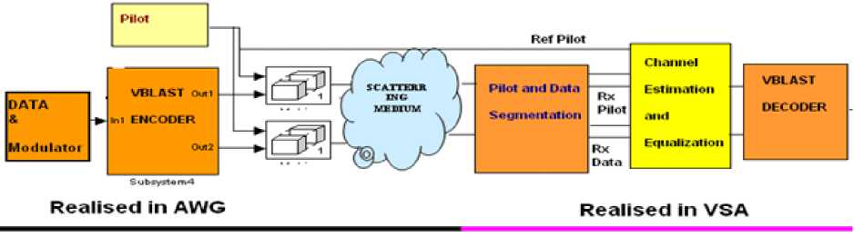
Fig. 7. Basic Block Diagram for Hardware Realization
Agilent VSA is a versatile signal analyzer of a new kind of instruments fully programmable via its own embedded Agilent 89600 VSA software and it is programmable from computer through MATLAB/SIMULINK. In VSA, the 1st job is to segregate the pilot from the data, then channel estimation and equalization. In the last stage 2x2 VBLAST decoder is implemented.
The total experiment is done in closed loop fashion with AWG and VSA (Figure 8).
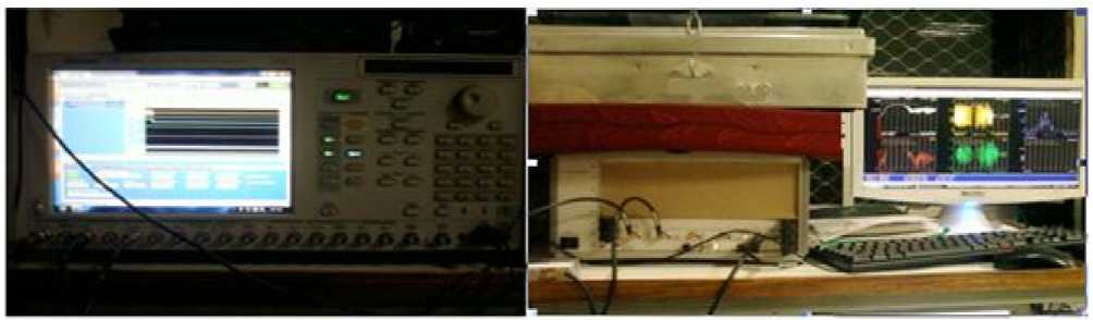
Fig. 8. Closed loop setup consist of AWG and VSA
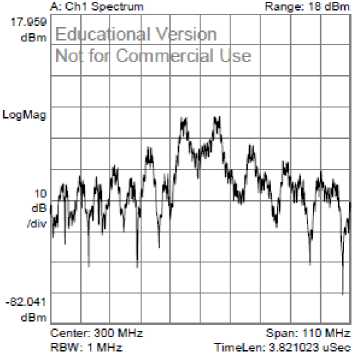
Fig. 9. Signal spectrum at 300 MHz RF frequency.
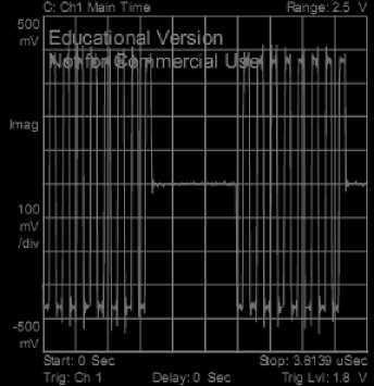
Fig. 10. Information data (Base band).
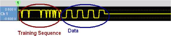
Fig. 11. Baseband Signal at the transmitter side after training symbol insertion for 1st channel (Real part).
As in the figure 7, information data stream is first modulated and the it is VBLAST encoded. Then training data stream is added to both of the coded data. Figure 11 shows the real part of the 1st transmitted data stream for channel 1.
After pilot insertion the data streams are up-converted to the RF level of 300 MHz and passed through channel. Figure below shows the signal after passing through channel.
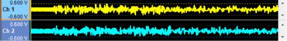
Fig. 12. RF Signal from AWG corrupted by the channel (-3dB SNR)
As in figure 12, because of low the SNR signal quality degraded as the noise floor over shoot the signal level.
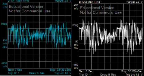
Fig. 13. Base band Received Signal at VSA (with -3dB SNR)
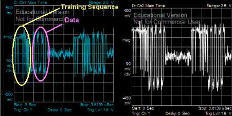
Fig. 14. Base band Received Signal at VSA (with 6 dB SNR)
Figure 13 and 14 represent the received base band signal at the VSA. It is clear from the figures that as the SNR value decrease the signal quality degraded.
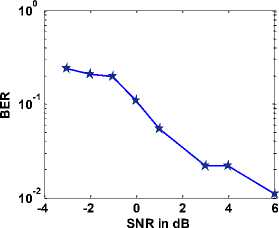
Fig. 15. SNR vs BER curve in closed loop condition.
Above figure shows the BER performance of the above said VBLAST system in closed loop form with AWG and VSA. Figure shows with the increase in SNR value the BER reduces.
-
VI. Conclusion
Through the simulation results, it is found that 2x2 VBLAST MIMO OFDM system provide better performance in comparison to single antenna OFDM system and conventional 2x2 VBLAT MIMO system. And MIMO-OFDM system provides better resistance against Doppler shift. Therefore VBLAST MIMO OFDM system is one of the best and suitable solutions in high mobility condition
References Performance Analysis of VBLAST Based MIMO OFDM System in Vehicular Channel
- http://www.transport-research.info/web/themes/ technology.cfm
- Thematic Research Summary: “Intelligent transport systems”, Transport Research Knowledge Centre, European commission, DG Energy and Transport, Prepared by Zuzana !itavancová Martin Hájek, Date 02/04/2009.
- http://egov.eletsonline.com/2012/08/sustainable-public-transportation-through-ict/
- EU. eSafety, “Final Report of the eSafety Working Group on Road Safety”, November, pp.7-39, 2002
- J. K. Hedrick, et al., “Control Issues in Automated Highway Systems”, IEEE Control Systems, Vol.14, No. 6, pp.21-32, 1994
- ITS Technical Note For Developing Countries, Toshiyuki Yokota, Sr . Transport Specialist Transport and Urban Development Department.
- ‘Intelligent Transport Systems and CLAM’ ITU Technology Watch Report 1, October 2007 (http://www.scribd.com/doc/17501030/Intelligent-Transport-Systems-and-CALM)
- Hyundong Shin, and JaeHong Lee, “On the Error Probability of Binary and M-ary Signals in Nakagami-m Fading Channels” IEEE TRANSACTIONS ON COMMUNICATIONS, VOL.52, NO.4, APRIL2004.
- Li Tang, Zhu Hongbo,”Analysis and Simulation of nakagami fading channel with Matlab,”Asia-Pacific conference on environmental electromagnetic CEEM’2003, China,pp. 490-494.
- M. Nakagami, “The m-distribution, a general formula of intensity distribution of rapid fading,” in Statistical Methods in Radio Wave Propagation, W. G. Hoffman, Ed, Oxford, England: Pergamum, 1960.
- Himal A. Suraweera and Jean Armstrong, “Performance of V-BLAST MIMO-OFDM Systems with Carrier Frequency Offset” Au sCTW 2005, 2005, pp-73-78
- J. Armstrong, P. M. Grant and G. Povey, “Polynomial cancellation coding of OFDM to reduce the intercarrier interference due to Doppler spread,” in Proc. IEEE GLOBECO M 98 , Sydney, Australia, Nov. 1998 , pp. 2771-2776.
- Srabani Mohapatra and Susmita Das, “Performance Enhancement of OFDM System with ICI Reduction Technique”, Proceedings of the World Congress on Engineering 2009, Vol 1, WCE 2009, July 1-3, 2009.
- Samarendra Nath Sur and Rabindranath Bera, “Doppler Shift Impact On The MIMO OFDM System In Vehicular Channel Condition” IJITCS, VOL.4, NO.8, July, 2012, pp- 57-62.
- Sang Goo Kim, Dongweon Yoon, Zhengyuan Xu, and Sang Kyu Park, “Performance Analysis of the MIMO Zero-Forcing Receiver over Continuous Flat Fading Channel”, ICIS, 23-25 June 2010
- A. Annamalai, and C. Tellambura, “Error Rates for Nakagami-m Fading Multi-channel Reception of Binary and M-ary Signals”, IEEE TRANSACTIONS ON COMMUNICATIONS, VOL. 49, NO.1, JANUARY 2001.
- M.K. Simon and M.-S. Alouini, “Digital Communication Over Fading Channels :A Unified Approach to Performance Analysis”. NewYork: Wiley,2000.
- Tahmid Quazi and HongJun Xu1, “Performance analysis of adaptve M-QAM over a fat-fading Nakagami-m channel”, S Afr J Sci. 2011;107(1/2), Art. #122, 7 pages. DOI: 10.4102/sajs.v107i1/2.122.
