Performance of High-Altitude Platforms Cellular Communications using Hamming-Tapered Concentric Circular Arrays

Author: Fahad Alraddady
Journal: International Journal of Information Technology and Computer Science(IJITCS) @ijitcs
Article in issue: 12 Vol. 6, 2014.
Free access
In this paper, the performance of cellular communications based on the ambitious technology of High-Altitude Platforms (HAPs) is discussed when using tapered concentric circular arrays. The coverage cell will be described and designed with an efficient beamforming technique where the Hamming window is proposed as a tapering function and applied to the uniform concentric circular arrays (UCCA) for sidelobe reduction. Based on establishing some mapping curves, this novel tapering window is optimized in its parameters to have the lowest possible sidelobe level that can be 45 dB below the main lobe level. The optimum weights of Hamming window are found to be function of the number of elements of the innermost ring and the number of rings in the array. The cell power pattern is also discussed where the out-of-cell radiation is greatly reduced which in turns reduces the co-channel interference and improves the Carrier-to-Interference Ratio (CIR).
High-Altitude Platforms, Tapered Beamforming, Concentric Circular Arrays
Short address: https://sciup.org/15012197
IDR: 15012197
Text of the scientific article Performance of High-Altitude Platforms Cellular Communications using Hamming-Tapered Concentric Circular Arrays
Published Online November 2014 in MECS DOI: 10.5815/ijitcs.2014.12.02
Recently, an emerging technology for wireless communications based on High-Altitude Platforms (HAPs) has gained attention due to its superior performance compared to conventional terrestrial and satellite systems [1-3]. HAPs may be in the form of Helium filled airships or circulating airplanes that can provide a variety of communications services for a long time. These platforms are positioned in the stratosphere at a preferable height of 20 km – the height at which the wind speed is minimum- and can cover several hundreds of kilometers diameter area. An important and key parameter of HAPs is the antenna technique used for providing communications to or from users in the cells. Fixed and spot-beam antennas are easy to use practically available but have no flexibility in the design of cells which is very important in conveying any changes in the system. On the other hand, Array processing techniques have considerable interests recently and the array configuration affects its performance greatly. Among the different array configurations circular arrays have various applications including sonar, radar, and mobile communications. It can be used for beamforming in the azimuth plane for example at the base stations of the mobile radio communications system. Another better array configuration is to use multiple concentric circular arrays (CCA) of different number of elements and radii [4-9]. Uniform CCA (UCCA) is one of the most important configurations of the CCA [8] where the interelement spacing in individual rings and the inter-ring spacing are kept almost half of the wavelength. The sidelobes in the UCCA will drop to about -17.5 dB especially at larger number of rings [8]. However, this sidelobe level still will be very high in some applications. Therefore, this paper is devoted for reducing the sidelobe level in UCCA using a Hamming amplitude weighting applied to the rings of the array. This tapering window is optimized to provide the lowest possible side lobe levels which indeed will improve the HAPs cellular systems as described in this paper.
The paper is arranged as follows; in section 2 discusses the UCCA geometry and section 3 introduces the Hamming tapering window. In section 4, the Hamming UCCA beamformer is introduced and the performance of beam power pattern, sidelobe levels and beamwidth is discussed in section 5. Finally section 6 concludes the paper.
-
II. Geometry of The UCCA
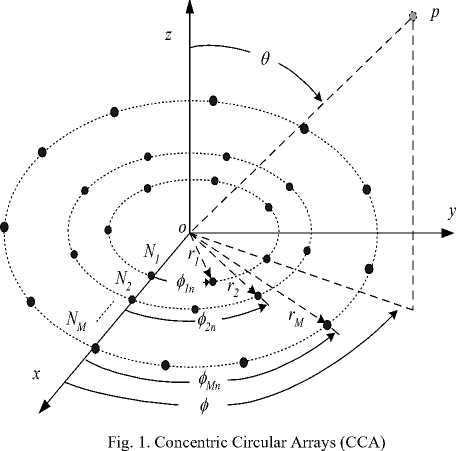
Concentric circular arrays (CCA) have gained a great attention for communications applications as it provides many advantages over other array configurations. The uniform azimuthally arrangement of elements makes the beams formed to be symmetric and the beamforming is azimuthally independent. Concentric circular antenna arrays has elements arranged in multiple concentric circular rings which differ in radius and number of elements as shown in Fig. 1, where there are M concentric circular rings. The mth ring has a radius r and number of elements N where m = 1, 2,..., M .
In array processing, it is generally assumed that all elements in the array are omnidirectional sensors; therefore the power pattern can be defined if we know the weighting and steering matrices of the array. An expression for the array steering matrix has been deduced in [8] and is given by:
AS ( 9 , ф ) =
|
jkr sin 9 cos ( ф - ф 11 ) e. ej jkiT^ain 9 cos ( ф - ф l2 ) |
^ jkr2 sin 9 cos ( ф — ф 21 ) e jkr 2sin 9 cos ( ф — ф 22 ) |
|
" jkr sin 9 cos ( ф - ^ N ) |
. . |
|
0 |
jkr2 sin 9 cos ( ф — ф 2 N-, e 2 |
|
0 |
0 |
|
0 |
0 |
|
_ 0 |
0 |
ejkkM sin 9 cos ( ф — Ф м 1 )
jkM sin 9 cos ( ф — Ф м 2 ) e
, jkM sin 9 cos ^-ф MNм - 1 , jkM sin 9 cos ^-ф MNм )
where the azimuth angle of the mnth element in the array is given by:
Ф mn = П , П = 1,2,3,..., N (2)
Nm
Each column in the array steering matrix represents the corresponding ring steering vector which in general for the mth ring is given by:
S (9 Ф)= [ejkrm sln9 cos(ф—фm 1) ejk,m sin 9cos(X—^m2 ) jkm, sin 9 cos(ф-фm„ ) 'v sln 9 coskф—фmNm ) T e ...e ]
.
.
.
Therefore, the array steering matrix may be rewritten as:
It is usually for the ring steering vectors to have different lengths as they have different number of elements therefore we append each column with zeros for lower length vectors in the array steering matrix.
If the interelement spacing in any array exceeds half of the wavelength, the resulted radiation pattern will have grating lobes of higher levels. On the other hand, if this distance is smaller than half of the wavelength, the pattern will have a wider main lobe and the mutual coupling between elements will increase. Therefore, the uniform concentric circular array (UCCA) configuration that has almost half of the wavelength separating distance either between neighboring elements in a ring or between any two neighboring rings is needed to have a reasonable radiation pattern and this can be obtained if the number of elements is incremented by 6 elements or:
N m + 1 = N m + 6
This gives inter-ring separation distance of 0.4775 X (which is the nearest possible value to half of the wavelength) which occurs only if for any ring the distance between any two neighboring elements is set half of the wavelength or:
2 n m = 0.5 x
N m
We can control the radiation pattern of the array by controlling the magnitudes and phases of the exciting currents, therefore the array factor or gain will be determined by the following equation
G (9, ф) = SUM {w (9, ф) HAS (9, ф)} (7)
where the SUM operator is the summation of the elements of the resulted matrix and W ( 9 , ф ) is the weight matrix that controls the amplitudes and phases of the input currents. To have a delay-and-sum beamformer, we can form the main lobe in the direction ( 9 , ф ) by setting the weight matrix to equal the array steering matrix at the same direction.
-
III. Beamformer for Hamming UCCA
0.54
+
0.46cos
Non-uniform amplitude weighting such as in tapered beamforming will improve the radiation pattern of any type of antenna array and results in lower sidelobe levels at the cost of larger beamwidth depending on the type of the utilized tapering window. In the case of UCCA, the tapering may be applied with an analogy to a linear onedimensional array, where the number of elements in the linear array is twice the number of rings; therefore, it will be usually an even number. The outermost ring will take the weight value that corresponds to the outermost elements of the linear array and proceeding inwardly to the innermost ring that has the same weighting as the two innermost elements in the one-dimensional array. Therefore, the highest amplitude weighting will be at the innermost ring while the smallest amplitudes are for the outermost ring. Beamforming using tapered amplitude windows in this case can be considered as a subarray processing as shown in Fig. 2 where all elements that correspond to a ring will have the same amplitudes and this will reduce greatly the processing burden and calculations that find each element-amplitude by other adaptive algorithms [8].
The Hamming window used for filter applications is modified here and gives the following rings coefficients for M rings UCCA:
pattern of the same array where the sidelobe level is reduced to about -30 dB.
w m
n( m — M — 2)
M + 1
m = 1,2,... M
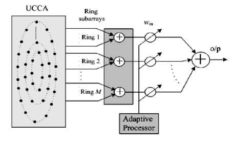
Fig. 2. Tapered beamformer applied to UCCA
The Hamming UCCA essentially affects the beams footprints and coverage performance of HAP cellular communications.
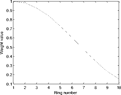
Fig. 3. Hamming window variation with the ring number in 10 rings UCCA
A. Cell Geometry and Axes
In this section we will discuss these effects in terms of the cells geometrical parameters such as the major and minor axes and cell area. In addition, the footprint of the beams outside their areas is demonstrated to show the relative received power levels on the ground for the Hamming tapered UCCAs. From these footprints, we can measure the cell axes, ground beamwidths and cells areas throughout the coverage area, which will be beneficial in the cellular design of the HAP system.
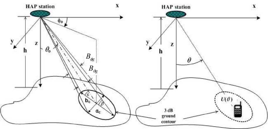
The HAP is located at an altitude about 20 km high , which is very small compared with the earth’s radius; we can approximate the earth as a flat surface. The cell as depicted in Fig. 5 is defined by the coverage beam that has a direction of ^ and cross section beamwidth of B e and В ф , and the projection of the beam on the ground will be an ellipse that has a major axis b and minor axis a . The major axis b is given by [10-15]:
f f B. A f bF = h I tan 9„ + — - tan 9„
F I o o
—
B θ
where the subscript F stands for flat ground approximation and h is the platform altitude in km.
The cell center point is located by an angle from the platform given by
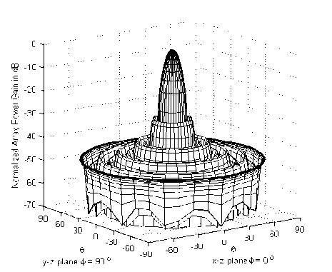
Fig. 4. Normalized power pattern for Hamming tapered UCCA of 10 rings.
Fig. 3 depicts the variation of the Hamming window for 10 rings UCCA and Fig. 4 displays the radiation
6C= tan—1|tan| 60--§■ 1 + b^l co
( V 2 ) 2 h J and the cell minor axis a can be given by:
Bh aF = 2 h sec ( 6J tan I
These two quantities (i.e. the minor and major axes) will define the cell shape and this assumption can be used for smaller and moderate coverage areas but when the coverage area increases the approximation error will increase and can’t be longer used and instead we apply the curved-earth cellular model where we take into consideration the earth curvature.
-
B. Ground Elevation Angle
The direction of the beam and its beamwidths form the basic parameters that affect its footprint. Relating the cell location with the elevation angle is practically very important, therefore, it is advantageous to express the coverage area in terms of the beam pointing directions or elevation angles and depicts the corresponding central distance in km away from the subplatform point shown in Fig. 5.
(a)
(b)
Fig. 5. Footprint of a HAP cell; (a) geometry for cell parameters and (b) geometry for power profile function
Assuming that the elevation angle at the cell center is denoted by £ , it can be related by the beam pointing direction, ^ , by the following approximate relation as:
£ = 90 - 6 o (12)
The minimum elevation angle of a cell в as depends on both the value of ^ and the ground beamwidth B^ and can be determined by:
B
в = 90 - - 9o (13)
where it decreases with either increasing B or increasing ^.
-
C. Power Profile Function and Ground Power Contours
Recalling the UCCA gain G (в, ф ) , which can be written as:
G ( в , ф) = SUM { W ( в , фф^ сА ( в , ф ) } (14)
where H is the complex conjugate transpose operator. Depending on the chosen weight matrix W , we have a beam footprint which represents the received signal power variation due to the array gain only, but there is another factor affecting the received signal power from a HAP which is the attenuation due to distance variation between the platform and mobile. These two factors can be integrated into one term denoted by the power profile function (or the received signal power gain) which can be deduced by considering the received signal power by a mobile from HAP. Assuming free-space propagation scenario between the HAP and mobile users, therefore we can write an expression for the received signal power Pr from a HAP by a mobile as:
I J
P = PG, (М^«Цп«J
where P is the transmitted HAP beam power, Gpr ( в , ф ) is the mobile antenna power gain, Gpt ( «, фф is the HAP array power gain given by:
G p, ( в , ф ) = G ( в , ф )2
and U ( в ) is the line-of-sight distance between the HAP and the mobile as shown in Fig. 6.1 (b) which can be determined from the following approximate equation:
u (e )= T^
cos ( в )
Therefore, the received signal power can be rewritten as:
I J
Pr = PtGpr(в,ф)| — I G(в,ф) cos2(в) ^ 4nh )
The received power depends on the array factor and the mobile location with respect to the HAP station assuming all the other quantities are constant. Therefore we may rewrite the last equation as:
Pr = Kp р(0,фф
where Kp is a constant and p ( 0 , фф is denoted by the power profile function and is given by:
p ( 0 , ф ) = | G ( 0,ф ) 2 cos 2 ( o ) (20)
This function represents the variation in the received signal power due to the array gain and the mobile location with respect to the HAP during the motion of the mobile station within the cell. Fig. 6 depicts the normalized power pattern footprints of the Hamming tapered UCCAs at N = 5 and M = 5 where the contours in each plot are separated by 3 dB. There is a great reduction in the sidelobe levels and almost has non-ring distribution around the mainlobe. Another important notice is that the power pattern in the region opposite to the mainlobe direction (i.e. the region that has an azimuth angle of ф о +180 ° and at almost the same elevation angles) has a raised sidelobe level which increases as ^ increases. Therefore, this region should be avoided if it is designed to utilize the frequency assigned in the opposite mainlobe in the frequency reuse plan, as it will result in excessive co-channel interference.
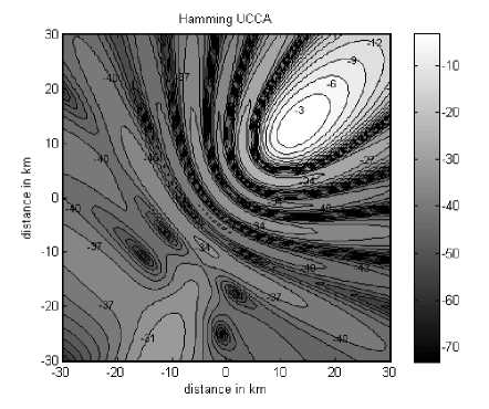
Fig. 6. Normalized power gain contours for Hamming UCCA
-
V. Ground Beamwidths and Cell Geometrical Parameters
The beam footprint will be a consequence of the utilized UCCA as shown later in the set of patterns in Fig. 6. The cell dimensions such as the major and minor axes ( b ,a ) and the cell area are affected by the beam direction and beamwidths, which in turn affect the ground elevation and azimuth beamwidths ( B B ). Therefore, og, ф we may discuss the variations of the ground beamwidths ( B , B ) for the different tapered UCCA at different beam directions and different number of rings, M , for the most suitable innermost ring size of 5 elements as shown in Fig. 7 and Fig. 8 respectively. The group of curves in Fig. 7 show that B increases with the increase tig in 5 and with the decrease in M while in Fig. 8, B^ is almost constant with the beam direction but decreases with increasing M . In Fig. 9, the major axis of the cell will increase slightly with increasing the pointing direction 0 up to 30 degrees while beyond this value it increases rapidly regardless of the number of rings in the array. In addition, the major axis decreases with increasing M as the beamwidth of the coverage beam will be narrower. It is worth noting that the nature of variation of the major axis is almost independent on the tapering window except at the starting values at 0o = 0°, which increases at lower sidelobe levels. This is because tapering will increase the beamwidths. In Fig. 10, the minor axis has a similar performance like that of major axis except that it is less sensitive to the increase in 0 ■ In addition, at 0o = 0°, the major axis have the same values and the footprint is therefore circularly shaped while the difference in the two cell axes increases as 5 increases and the cell becomes elliptic in shape and its area will be:
, na b
Acell = -^C-C (21)
Fig. 11 depicts the variation of the cell area for the different tapered UCCA at different cell locations or directions. The cell area will increase by either increasing the 5 or decreasing M . It also increases by reducing the sidelobe level at the same number of rings and pointing direction.
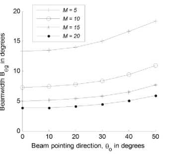
Fig. 7. Ground elevation beamwidth in degrees versus beam direction at different number of rings for the Hamming UCCA.
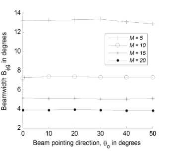
Fig. 8. Ground azimuth beamwidth in degrees versus beam
Фд direction at different number of rings for the Hamming UCCA.
Hamming-Tapered Concentric Circular Arrays
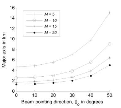
Fig. 9. The major axis b in km versus beam direction at different number of rings for the Hamming UCCA.
arrays and in this paper has been defined for UCCA where we apply the Hamming weights directly to the arrays elements by dividing the UCCA into circular subarrays in which the elements are amplitude weighted by the same coefficient. The performance of cellular system such as cell boundaries and axes, cell area, and sidelobe levels have been described and discussed extensively. The simulation results show that the sidelobe levels out of the main cell area are greatly reduced which means low co-channel interference at other co-channel cells and higher carrier-to-interference rations will result in cellular frequency reuse systems.
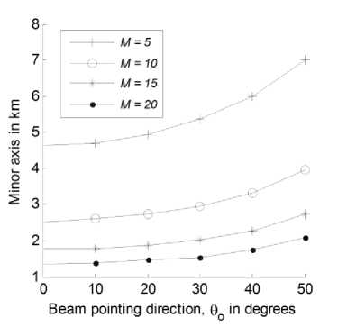
Fig. 10. The minor axis a in km versus beam direction at different number of rings for the Hamming UCCA.
-
[1] S. Karapantazis and F. Pavlidou, "Broadband communications via high-altitude platforms: a survey," IEEE Communications Surveys & Tutorials, vol. 7, pp. 231, 2005.
-
[2] A. Mohammed and Z. Yang, “Broadband Communications and Applications from High Altitude Platforms”, International Journal of Recent Trends in Engineering, Vol 1, No. 3, May 2009.
-
[3] A. Mohammed and T. Hult, Capacity Evaluation of a High Altitude Platform Diversity System Equipped with Compact MIMO Antennas”, ACEEE International Journal on Communication, Vol 1, No. 1, Jan 2010.
-
[4] S. C. Chan, and H. H. Chen, "Uniform Concentric Circular Arrays with Frequency-Invariant Characteristics—Theory, Design, Adaptive Beamforming and DOA Estimation", IEEE Transactions on Signal Processing, Vol. 55, No. 1, pp. 165-177, January 2007.
-
[5] Y. Albagory, M. Dessouky, H. Sharshar, “An Approach for Dolph-Chebyshev Uniform Concentric Circular Arrays,” Journal of Electromagnetic Waves and Applications, JEMWA, Vol.21, No.6, pp.781 –794, 2007.
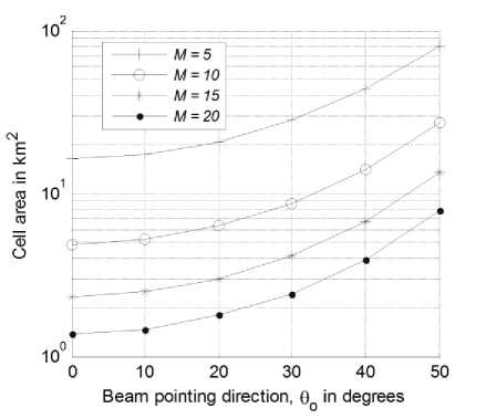
Fig. 11. Cell area in square km versus beam direction at different number of rings for the Hamming UCCA.
-
[6] Y. Albagory, M. Dessouky, H. Sharshar, “Optimum Normalized-Gaussian Tapering Window for Side Lobe Reduction in Uniform Concentric Circular Arrays,” Progress In Electromagnetics Research, PIER 69, pp. 35 – 46, 2007.
-
[7] Y. Albagory, M. Dessouky, H. Sharshar, " An Approach for Low Sidelobe Beamforming in Uniform Concentric Circular Arrays" International Journal of Wireless Personal Communications, vol. 43, no. 4, pp. 1363-1368, 2007, Springer.
-
[8] M Nofal, S Aljahdali, Y Albagory, “Tapered beamforming for concentric ring arrays” AEU-International Journal of Electronics and Communications 67 (1), 58-63, 2013.
-
[9] Y. Albagory, “A Novel Design of Arbitrary Shaped Cells for Efficient Coverage from High Altitude Platforms” Progress In Electromagnetics Research Letters, Vol. 1, 245-254, 2008.
-
[10] Moawad Dessouky, Hamdy Sharshar, Yasser Albagory “Improving The Cellular Coverage from A High Altitude Platform by Novel Tapered Beamforming Technique,” Journal of Electromagnetic Waves and Applications, JEMWA, Vol.21, No.13, pp. 1721 –1731, 2007.
VI. Conclusion
In this paper we have applied the Hamming coefficient weighting for the concentric circular arrays (UCCA) for cell formation in HAPs mobile communications. This weighting method is used for sidelobe reduction in linear
-
[11] Mostafa Nofal, Yasser Albagory, Mohiy Hadhoud, Moawad Dessouky, “A Novel Cellular Structure for Stratospheric Platform Mobil Communications “, Proc. of the Nineteenth National Radio Science Conference, NRSC’2002, March 19-21, Faculty of Engineering, Alexandria University, Alexandria, EGYPT, 2002.
-
[12] MI Dessouky, HA Sharshar, YA Albagory, “Geometrical analysis of high altitude platforms cellular footprint”, Progress In Electromagnetics Research 67, 263-274, 2007.
-
[13] MI Dessouky, HA Sharshar, YA Albagory, “Design of high altitude platforms cellular communications”, Progress In Electromagnetics Research 67, 251-261, 2007.
-
[14] Mostafa Nofal, Yasser Albagory, Moawad Dessouky, Hamdy Sharshar, “Modeling and Investigating the Rotational Motion Effects of the High Altitude Platforms,” Twenty Second National Radio Science Conference (NRSC 2005) March 15-17, 2005 Cairo – Egypt.
-
[15] Sultan Aljahdali, Mostafa Nofal and Yasser Albagory, "Geometrical Correction for Cell Deployment in
Stratospheric Cellular Systems", Progress In
Electromagnetics Research C, Vol. 29, pp. 83-96, 2012.
References Performance of High-Altitude Platforms Cellular Communications using Hamming-Tapered Concentric Circular Arrays
- S. Karapantazis and F. Pavlidou, "Broadband communications via high-altitude platforms: a survey," IEEE Communications Surveys & Tutorials, vol. 7, pp. 2-31, 2005.
- A. Mohammed and Z. Yang, “Broadband Communications and Applications from High Altitude Platforms”, International Journal of Recent Trends in Engineering, Vol 1, No. 3, May 2009.
- A. Mohammed and T. Hult, Capacity Evaluation of a High Altitude Platform Diversity System Equipped with Compact MIMO Antennas”, ACEEE International Journal on Communication, Vol 1, No. 1, Jan 2010.
- S. C. Chan, and H. H. Chen, "Uniform Concentric Circular Arrays with Frequency-Invariant Characteristics—Theory, Design, Adaptive Beamforming and DOA Estimation", IEEE Transactions on Signal Processing, Vol. 55, No. 1, pp. 165-177, January 2007.
- Y. Albagory, M. Dessouky, H. Sharshar, “An Approach for Dolph-Chebyshev Uniform Concentric Circular Arrays,” Journal of Electromagnetic Waves and Applications, JEMWA, Vol.21, No.6, pp.781 –794, 2007.
- Y. Albagory, M. Dessouky, H. Sharshar, “Optimum Normalized-Gaussian Tapering Window for Side Lobe Reduction in Uniform Concentric Circular Arrays,” Progress In Electromagnetics Research, PIER 69, pp. 35 –46, 2007.
- Y. Albagory, M. Dessouky, H. Sharshar, " An Approach for Low Sidelobe Beamforming in Uniform Concentric Circular Arrays" International Journal of Wireless Personal Communications, vol. 43, no. 4, pp. 1363-1368, 2007, Springer.
- M Nofal, S Aljahdali, Y Albagory, “Tapered beamforming for concentric ring arrays” AEU-International Journal of Electronics and Communications 67 (1), 58-63, 2013.
- Y. Albagory, “A Novel Design of Arbitrary Shaped Cells for Efficient Coverage from High Altitude Platforms” Progress In Electromagnetics Research Letters, Vol. 1, 245-254, 2008.
- Moawad Dessouky, Hamdy Sharshar, Yasser Albagory “Improving The Cellular Coverage from A High Altitude Platform by Novel Tapered Beamforming Technique,” Journal of Electromagnetic Waves and Applications, JEMWA, Vol.21, No.13, pp. 1721 –1731, 2007.
- Mostafa Nofal, Yasser Albagory, Mohiy Hadhoud, Moawad Dessouky, “A Novel Cellular Structure for Stratospheric Platform Mobil Communications “, Proc. of the Nineteenth National Radio Science Conference, NRSC’2002, March 19-21, Faculty of Engineering, Alexandria University, Alexandria, EGYPT, 2002.
- MI Dessouky, HA Sharshar, YA Albagory, “Geometrical analysis of high altitude platforms cellular footprint”, Progress In Electromagnetics Research 67, 263-274, 2007.
- MI Dessouky, HA Sharshar, YA Albagory, “Design of high altitude platforms cellular communications”, Progress In Electromagnetics Research 67, 251-261, 2007.
- Mostafa Nofal, Yasser Albagory, Moawad Dessouky, Hamdy Sharshar, “Modeling and Investigating the Rotational Motion Effects of the High Altitude Platforms,” Twenty Second National Radio Science Conference (NRSC 2005) March 15-17, 2005 Cairo – Egypt.
- Sultan Aljahdali, Mostafa Nofal and Yasser Albagory, "Geometrical Correction for Cell Deployment in Stratospheric Cellular Systems", Progress In Electromagnetics Research C, Vol. 29, pp. 83-96, 2012.
