Performance of Linear Block Coding for Multipath Fading Channel

Author: Hemlata Sinha, M.R. Meshram, G.R. Sinha
Journal: International Journal of Information Technology and Computer Science(IJITCS) @ijitcs
Article in issue: 8 Vol. 4, 2012.
Free access
This paper deals with the performance of linear block codes which provide a new paradigm for transmission over multipath fading channels. Multi path channel fading is the main enemy for any wireless communications system. Therefore, for any novel approach applied at any wireless communication system, its efficiency is measured according to its ability of mitigating the distortion caused by fading. It causes time dispersion to the transmitted symbols resulting in inter symbol interference (ISI). ISI inter symbol interference problem is a major impairment of the wireless communication channel. To mitigate the ISI problem and to have reliable communications in wireless channel, channel equalizer and channel coding technique is often employed. In this paper the BER (Bit Error Rate) performance is shown from analytically and by means of simulation for multipath dispersive channels. We have designed a channel equalizer using MLSE (Viterbi algorithm) in this paper for such a multipath channel (introducing inter symbol interferences) with BPSK modulation based on the assumption that the channel can be perfectly estimated at the receiver. Obviously the performance of channel coding in terms of BER is better than uncoded channel.
BER, BPSK, Linear block code, SNR, Viterbi algorithm, Maximum-likelihood sequence estimator (MLSE), ISI
Short address: https://sciup.org/15011724
IDR: 15011724
Text of the scientific article Performance of Linear Block Coding for Multipath Fading Channel
Published Online July 2012 in MECS
The Viterbi algorithm was proposed in 1967 as a method of decoding trellis codes. In this paper this Viterbi decoding is considered and the bit error rate performance is evaluated for convolution code and it is compared with the bit error rate for uncoded signal under multipath fading channel. The inherent non-linear frequency response of a channel. Channel equalization [6][8] and channel coding can be implemented to combat ISI . We design a MLSE channel Equalization using Viterbi algorithm scheme[9] where BER so obtained is compared with theoretical BER and performance is analyzed. The same process is repeated by using channel coding and both the schemes are matched to see the effective gain.
-
II. Channel
In communications, the AWGN channel model is one in which the only impairment is the linear addition of wideband or white noise with a constant spectral density (expressed as watts per hertz of bandwidth) and a Gaussian distribution of amplitude. The model does not account for the phenomena of fading, frequency selectivity, interference, nonlinearity or dispersion. However, it produces simple, tractable mathematical models which are useful for gaining insight into the underlying behavior of a system before these other phenomena are considered. AWGN is commonly used to simulate background noise of the channel under study, in addition to multipath, terrain blocking, interference, ground clutter and self-interference that modern radio systems encounter in terrestrial operation.
-
A. Channel Modeling
The channel has three paths, which can be modeled as a FIR filter.
Hto = 1 - 0.5г-1 + 0.2г
The channel states are:
Я(к) = 5(k) - 0.5(fc - 1) + 0.2(k - 2) (2)
The delay factors are used to model the ISI (Inter Symbol Interference) present in the channel [6, 7]. The symbolic block diagram of the channel is given below:
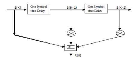
Fig 1.Channel modeling
Eight channel states are represented in the following table
Table1 Eight channel state
|
S(k) |
S(k-1) |
S(k-2) |
R(k) |
|
1 |
1 |
1 |
0.7 |
|
1 |
1 |
-1 |
0.3 |
|
1 |
-1 |
1 |
1.7 |
|
1 |
-1 |
-1 |
1.3 |
|
-1 |
1 |
1 |
-1.3 |
|
-1 |
1 |
-1 |
-1.7 |
|
-1 |
-1 |
1 |
-0.3 |
|
-1 |
-1 |
-1 |
-0.7 |
-
B. Additive White Gaussian Noise (AWGN) Channel
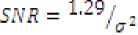
An additive white Gaussian noise is added to the signal in the channel. A parameter K is used to calibrate the noise gain in order to control SNR. The factor K is estimated by as follows:
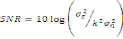
where σ2 s = signal power (variance)
σ2 n = noise power (variance)
-
III. Channel Equalizer
As the channel has inter-symbol interference (ISI), a channel equalizer has to be used in order to minimize the interference and to minimize the effect of the noise. We considered that the channel has three path Therefore we can generate 8 channel states. The equalizer employs maximum likelihood sequence estimate (MLSE) [8][9][10] .
-
A. Maximum Likelihood Sequence Estimation
We are using the Viterbi algorithm for MLSE [10][11] . The Viterbi algorithm provides an efficient way of finding the most likely state sequence in the maximum a posterior probability sense of a process assumed to be a finite-state discrete-time Markov process.
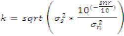
Fig 2: State diagram
To illustrate how the Viterbi algorithm obtains this shortest path [13][14] we need to represent the Markov process in an easy way. A state diagram, for the channel is as shown in Fig. 2, is often used. In this state diagram, the nodes (circles) represent states, arrows represent transitions, and over the course of time the process traces some path from state to state through the state diagram more redundant description of the same process is shown in Fig. 3, this description is called trellis. In a trellis, each node corresponds to a distinct state at a given time, and each arrow represents a transition to some new state at the next instant of time. The trellis begins and ends at the known states. Its most important property is that to every possible state sequence there corresponds a unique path through the trellis. The Viterbi algorithm is based on the Trellis
diagram (sample shown below)
input ”-1”
input ”1”
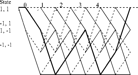
Fig.3: Example Trellis diagram
case, the probability of error is most affected by the channel states nearest to the decision boundary, i.e. the channel states with the minimum distance and hence the largest probability of error. To find the nearest distance, the direct approach is to evaluate all the distance and find its minimum as follows:
Based on these signal patterns, we can design decision boundaries by using minimum distance decision rule. Due to AWGN, the y(n) may shift a little because of the noise Next, we will calculate the theoretical BER based on BPSK and Channel equalizer. From the above table we have
S (k) =+1, H 1 => r (k) = 0.7, 0.3, 1.7, 1.3
S (k) = -1, H 2 => r(k) = -1.3,-1.7,-0.3,-0.7
In the paper, the FIR filter is designed from equation (1) and (2)
Н(^) = 1 — 0.5z-1 + 0.2z-2
Я(к) = S(k) - 0.5(k - 1) + 0.2(k - 2)
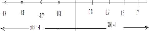
Fig.4: Theoretical Analysis using Minimum Distance Detection
Here, R(k) is the output of the channel and S is the transmitted signal. By using the relation
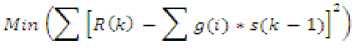
the distance between states is calculated and the cumulative distance is determined. The minimum value is taken and the path is traced back to find the Maximum likelihood sequence. The Viterbi Algorithm can be summarized as follows:
The decoder has to find the bit sequence that generates the state sequence that is nearest to the received sequence. Each transition in the trellis depends only on the starting state and the end state. We know what would be the output from a state (without a noise). The noiseless state output gives the mean value for the observation. The noise is Gaussian and we can calculate the probability based on the state transition and the received symbol .The total probability for a state sequence is the multiplication of all the probabilities along the path of the “state sequence” in the Markov chain. For all transitions in the trellis compute the sum of the matrix in the initial state and in the transition. At each state select among the incoming paths the one with the minimum matrix (the surviving path).
We are using Maximum Likelihood Sequence estimation (MLSE) to find BER practically.
-
B. Minimum Distance Decision
When the equalization problem is linearly separable, all the channel states can be classified correctly. In this
The error probability is given by:
Pr (e) = Pr (e|H 1 ).Pr (H 1 ) + Pr (e|H 2 ).Pr (H 2 ).
Because of symmetry and equi-probability of +1 and -1 (or 0 and 1) signals, we have
Pr (e|H 1 ) = Pr (e|H 2 ).
So, Pr (e) = Pr (e|H 1 )
PrCelH^ =
V4 [Pr(elHvs(k - 1) = l,s(k - 2) = 1) +
PrCel^.sCk - 1) = l,s(k - 2) = -1) + Pr(elHvs(k - 1) = -l,s(k - 2) = 1) +
Pr(elHvs(k - 1) = -l,s(k - 2) = -1)}
PrCel^) = {(?(0-3/ff)+ (?(°-7/a) + (L3/a) +
(L7a)}
(7) Also, since we are using BPSK, the number of symbols equals the number of bits. So,
BER = Pr(p) = P-rte H^) (8)
The Signal Variance
E.
= V4 {О.З- —
Hence,
Thus the BER can be expressed as:
ВЕЯ =
[(о.з(5^(5^я/1129)))] + [$(0.7(^(^/129)))] + ^^(^(^/ггд)))]4"
^^(^(^/w)))]
-
C. The Viterbi Algorithm
Let the trellis node corresponding to state at time I be denoted. Each node in the trellis is to be assigned a value based on a metric. The node values are computed in the following manner.
-
1. Set = 0 and I = 1
-
2. At time I, compute the partial path metrics for all paths entering each node.
-
3. Set equal to the smallest partial path metric entering the node corresponding to state at time i. Ties can be broken by previous node choosing a path randomly. The non surviving branches are deleted from the trellis. In this manner, a group of minimum paths is created from.
-
4. If I , where L is the number of input code segments (k bits for each segment ) and m is the length of longest shift register in the encoder, let I = I + 1 and go back to step 2 . Once all node values have been computed, start at state, time I = L + m, and follow the surviving branches through the trellis. The path thus defined is unique and corresponds to the decoded output. When hard decision decoding is performed, the metric used is the Hamming distance, while the Euclidean distance is used for soft decision decoding.
-
D. BER Computation with Channel Coding
For coding the message linear block code [6,3,3] is and Standard Array method for decoding them back.
Probability of message bits in error, that is, Coded BER is given by:
Pr (e) = (1/3).E {number of bits/codeword in error}
Any bit that is 1 in the first three bits of any error pattern contributes to message symbols in error
As this is a systematic code with first three bits the same as message bits. For the given Standard Array, it is calculated as:
Pr (error) = 1/3*[Pr {e in second column} + Pr {e in third column} + Pr {e in fourth Column} +2Pr {e in fifth column} + 2Pr {e in sixth column} + Pr {e in seventh column} + 3Pr {e in eighth column}]
^(₽rror) = 7 е: (1-е)4 +12 е3 (1-е)3 + 8 е4 (1-е)2 + 4 е5 (1-е) 4-е6
(12) Where ‘ε’ is the error probability of the binary symmetric channel. For the given case, we can estimate it assuming that Noise is AWGN and since the only symbols transmitted are +1 and -1, it can be estimated from the noise pdf.
Specifically, it is estimated as the probability that the noise as a random variable takes up values either less than -1 or greater than +1.
-
IV. Simulation
The simulations are carried out using MATLAB software. The performance is simulated and evaluated for BPSK systems. Based on data generated by computer simulation of BPSK modulation techniques for BER calculation the following results are obtained.
-
1. Bit Error Rate (BER) versus Signal-to-Noise ratio (SNR) over Rayleigh fading channel for BPSK modulation scheme without channel coding technique.
-
2. BER versus SNR over multipath fading channel for BPSK modulation scheme with channel coding technique.
-
A. To calculate BER obtained via MLSE, i.e., without channel coding
Steps of Simulation:
-
1. Generate random information Bits.
-
2. Generate the guard bits and the unique words.
-
3. Generate the bursts using information bits,
-
4. Transmit the pulse shaped burst using FIR
-
5. Add noise with the transmitted signal and perform SNR calibration.
-
6. Calibration factor,
guard bits and the unique word.
channel.
К = sqrt ^signal power) /((noise power)«10ACSNfl/10))'
-
B. To calculate BER obtained via MLSE, i.e., with channel coding
Steps of Simulation:
-
1. Generate random information bits.
-
2. Then channel coding using linear block code [6 3 3 ] is used with the information bits.
-
3. Generate the guard bits and the unique words.
-
4. Generate the bursts using the coded information bits, guard bits and the unique words.
-
5. Transmit the pulse shaped burst using FIR channel.
-
6. Add noise with the transmitted signal and perform SNR calibration
-
7. Calibration factor K.
V. Performance Evaluation
This paper presents a simulation study on the performance comparison analysis of coded and uncoded channel with MLSE Equalizer based receiver for multipath fading wireless channel. The simulation result of uncoded channel is evaluated on BER vs. SNR for channel equalizer when the number of data is 300bits and the BERs are obtained by varying the values of SNR in the range of 0 to 30 dB
A. BER obtained via MLSE without channel coding
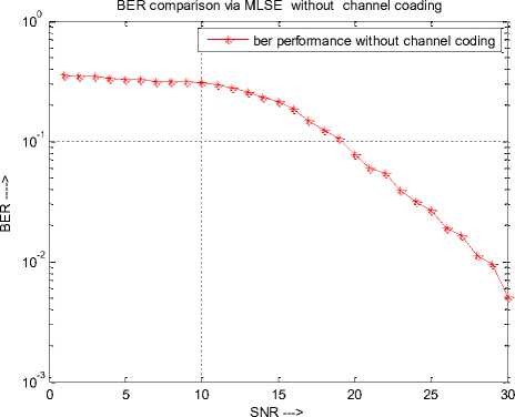
Fig 5:BER performance without Channel coding using MLSE
B. BER obtained via MLSE with channel coding
BER ---->
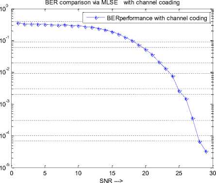
Fig 6: BER performance with Channel coding using MLSE
-
C. BER Comparison Of MLSE without channel coding and with channel coding
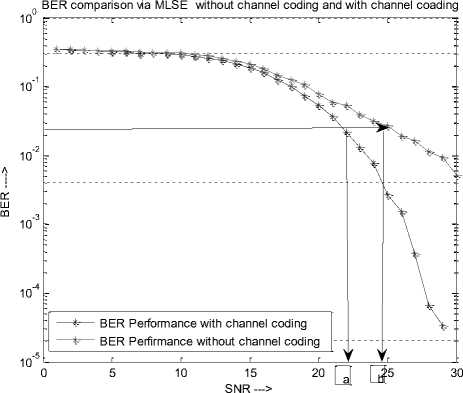
Fig 7: BER performance without and with Channel coding using MLSE
-
VI. Conclusions
The downward slope of BER curve of coded channel is sharper than uncoded channel after 21 dB in the simulated curve. Consequently, a specific BER and the SNR of coded and uncoded system are ‘a’ and’ b’ dB respectively. So coding gain is (b-a) dB. From the cross-sectional point, the coded channel performance is better than uncoded channel. From this simulation it is proved that if the data signal is transmitted using channel coding the system performance is clearly improved when the SNR is greater than 21 dB. The gain achieved by using channel coding in our simulations for a BER was approximately 2.2 dB which is very large when compared to the signal without channel coding.
References Performance of Linear Block Coding for Multipath Fading Channel
- John R. Barry, E. A. Lee, D. G. Messerschmitt, Digital Communication, 3rd ed, Kluwer Academic.
- John Proakis, Digital Communications, 4th ed. McGraw-Hill Higher Education, 2000.
- Andre Neubauer, Jurgen Freudnberger, Coding Theory,1st ed,John Wiley & Sons,Ltd 2007.
- Viterbi, Andrew J. and Audrey M. Viterbi. Nonlinear Estimation of PSK Modulated Carrier Phase with Application to Burst Digital Transmission. IEEE Trans. Information Theory, July 1983,29(4):543-551.
- John R. Barry, E. A. Lee, D. G. Messerschmitt, Digital Communication, 3rd ed, Kluwer Academic. Journal of Software,2001,12(9):1336-1342(in Chinese)
- Yannis Kopsinis and Sergios Theodoridis. An efficient low complexity technique for MLSE equalizers for linear and non linear channels. IEEE Trans. On Signal Processing, December 2003,51(12).
- Bernard Sklar. Rayleigh Fading Channel in Mobile Digital Communication System Part I: Characterization. IEEECommunication Magazine, July 1997, 90-100.
- Simon Haykin. Digital Communication. Wiley – India.
- Rong-Hui Peng, Rong-Rong. Chen Markov Chain Monte Carlo Detectors for Channels with Intersymbol Interference. IEEE transactions on signal processing , april 2010 , 58( 4).
- Yannis Kopsinis and Sergios Theodoridis. An efficient low complexity technique for MLSE equalizers for linear and non linear channels. IEEE Trans. On Signal Processing December 2003,51(12).
- G. D. Forney, Jr..Maximum likelihood sequence estimation of digital sequences in the presence of intersymbol interference. IEEE Trans. Inform. Theory, May1972 , 18: 363–378.
- Yannis Kopsinis and Sergios Theodoridis. An efficient low complexity technique for MLSE equalizers for linear and non linear channels .IEEE Trans. On Signal Processing, December 2003,51(12).
- W. Sauer-Greff, et al. Adaptive Viterbi Equalizers for Nonlinear Channels, in Proc. IEEE SignalProcessing Poznan, Poland, 2000.
- Andrew J. Viterbi. Error Bounds for Convolutional Codes and an Asymptotically Optimum Decoding Algorithm. IEEE Transactions on Information Theory, April, 1967,13:260-269.
