PID controller design for SOPDT using direct synthesis method

Author: Munna Kumar, Ram Sharan Singh
Journal: International Journal of Intelligent Systems and Applications @ijisa
Article in issue: 9 vol.11, 2019.
Free access
Direct synthesis method based PID controller was proposed for the second order plus dead time stable process having a zero in the numerator. The desired closed loop transfer function was considered as a second order time delay model and the Maclaurin series expansion technique was used to convert the obtained controller into the ideal form of the PID controller. The tuning parameter α was selected in such a way that gives the robustness level i.e. maximum sensitivity Ms value in the range of 1.2-1.8 which was the same as other recent tuning methods. The proposed method was applied to six different first and second order time delay process. The closed-loop performance in term of various performance indices such as settling time (ts), rise time (tr), Overshoot (%OS), and the time integral error indices such as IAE, ISE, and ITAE was compared to other similar design approaches. The comparative results show that the proposed method was superior to other methods.
Maclaurin series, maximum sensitivity, PID, direct synthesis, SOPDT
Short address: https://sciup.org/15016623
IDR: 15016623 | DOI: 10.5815/ijisa.2019.09.06
Text of the scientific article PID controller design for SOPDT using direct synthesis method
Published Online September 2019 in MECS
The process industries such as chemical, biochemical and pharmaceuticals industries used PID controller in more than 95% of the bottom layer control loop of the plant due to its simple structure, easy implementation, robust nature, and required less maintenance according to Åström and Hägglund [1]. The PID tuning is a challenging task due to variations in the process parameters, operating parameters and desired performance criteria. Therefore, a single tuning method cannot work for the different process models and at different operating conditions.
A large number of PID design techniques are available in the literature for different forms of the process models, and which are based on the different performance objectives and constraints. Ziegler and Nichols [2] (Z-N) and Cohen and coon [3] are two early and well-known design methods that provide the excellent closed-loop response for first order time delay process (FOPDT). These techniques are based on step response method whose closed-loop response gives quarter decay ratio. Z-N tuning rule gives excellent response for set point tracking and shows poor performance in case of disturbance rejection. This method fails in case of delay dominant and integrating process models. The PI/PID tuning rules based on process reaction curve was suggested by Åström and Hägglund [4] and Tyreus and Luyben [5]. Internal model control (IMC) and IMC based PID proposed by Rivera, et al. [6] improved the closed loop performance and showed better results than the conventional tuning approaches. The direct synthesis method similar to the IMC tuning rule developed by Smith and Corripio [7] also gives improved closed loop performance than the conventional tuning rule for both cases set-point as well as disturbance rejection. Rao et al. [8] designed the PID controller in series with a lead/lag compensator for integrating the process with time delay using the direct synthesis method. The H2 minimization technique was applied for designing of optimal IMC controller and further, the obtained controller was rearranged into a standard form of PID by using Maclaurin series approximation [9]. The proposed optimal controller provides better performance than many of previous design methods.
Performance-robustness trade-off is a challenging job in designing the controllers, and these characteristics of the controller depend on its tuning parameter. Therefore, a proper and simple guideline for the selection of the tuning parameter is needed to obtain a robust controller which provide better closed-loop performance. A large number of selection procedures of tuning parameter are available in the literature to obtain both nominal as well as robust performance. The tuning parameter was represented in term of the peak value of the sensitivity function i.e. maximum sensitivity ( Ms ) [10]. The proposed Ms based PID controllers tuning rule gives better performance-robustness trade-off. Alfaro et al. [11] developed an Ms based analytical equation for PI controller for stable systems. Arrieta et al. [12] designed a PID controller for stable systems with servo/regulatory problems based on Ms criteria and applied successfully for designing the controller in a constraint optimization problem. Begum et al. [13] used H2 minimization to design the IMC-PID controller. Since the obtained controller was not in the standard form of PID controller, the Maclaurin series approximation was used to convert into an ideal form of PID. This method was proposed for unstable first-order plus dead-time (UFOPDT) and recommended a systematic guideline for the selection of
Ms based tuning parameter. Since Ms is an important parameter which decides the closed-loop performance and robustness of the controller, the performance of the controller is characterized in the form of % overshoot (%OS), settling time (t s ), rise time (t r ), and time integral error criteria such as integral of absolute error (IAE), integral of square error (ISE) and time-weighted integral of absolute error (ITAE). Overshoot is eliminated or reduces by using setpoint weighting function or a set point filter Åström and Hägglund [4, 14].
Lee et al. [15] suggested a double feedback control loop and designed a simple PID controller and set point weight to reduce the undesirable overshoot. Shamsuzzoha and Lee [10] and Lee, et al. [15] used Maclaurin series expansion to design IMC-PID controller along with a setpoint filter to improve loop performance. Vijayan and Panda [16] proposed a double-feedback loop method in which the inner control loop was used to stabilize the system while the outer loop is used to control the process. Ziegler–Nichols or auto-tuning based relay feedback tuned the inner loop controller method and the IMC-PID controller was designed to control the outer loop. A cascaded feedback control loop suggested for stable and unstable process models used three controllers [17]. The primary loop consists of two controllers while the secondary loop contains one controller and designed by IMC theory. An optimal PI/PID controller was designed for stable and integrating first order with an inverse response by minimizing time integral error criteria [18, 19]. The undesirable overshoot was reduced by applying a first order set-point filter whose time constant was the same as tuning parameter ( α ) of IMC-PID controller. The robust techniques with minimum error involve lengthy calculations and design procedure and the simple PID design techniques Chidambaram and Saxena [20] are sluggish and fail to provide satisfactory results in the case of model uncertainty.
In this paper, a simple approach of PID tuning based on direct synthesis method for the second order time delay process (SOPDT) is proposed. The desired closed-loop transfer function is assumed as a second order time delay system whose time constant α is considered as a tuning parameter of the controller. The Maclaurin series approximation is applied for the conversion of an obtained controller into an ideal form of PID. The tuning parameter ( α ) was selected based on Ms value which provides fast and robust closed-loop performance. The Ms Value was chosen in the range of 1.2-1.8 for a stable process. The designed controllers applied to various examples comprising of FOPDT and SOPDT with or without zero in the numerator.
The present study is divided into the following section: Section II represents the related work. Section III elaborates the controller design procedure. Section IV represents the simulation studies of the different process model and performance comparisons to other similar tuning methods. Finally, the conclusions of the present work presented in section V.
-
II. Related Work
Several well-known PID tuning rule for first and second order time delay process have been developed and used in the chemical process industries over the years. Most of the PID used in the industries are poorly tuned and does not provide satisfactory or desired closed-loop performance [1]. Most of the chemical plants still use the well-known methods Ziegler and Nichols [2] (Z-N) and Cohen and coon [3] developed for first order time delay process (FOPDT) and these methods provide an excellent closed-loop response. Smith and Corripio [7] developed the direct synthesis method similar to IMC tuning rule which overcomes the problem of conventional PID tuning rules and gives improved closed loop performance for both cases set-point and disturbance rejection. The PID with a lead/lag compensator for integrating process was proposed by Rao et al. [8]. A double feedback control loop was suggested by [15, 16] for controlling the several forms first and second order time delay stable and unstable process. The primary control loop was stabilized by simple Z-N tuning or relay auto-tuning method while the secondary controller was designed by direct synthesis or IMC theory [16]. The controller designed by direct synthesis or IMC principle does not obtain in the standard form of PID. Therefore, the Maclaurin series expansion rule is used to obtain a controller in the standard form of PI/PID [10, 15, 21-23]. The IMC-PID designed controller shows an overshoot for set-point tracking due to the presence of zeros in the numerator of the filter selected in designing of IMC controller. The overshoot can be minimized by using a set-point filter or set-point weighting parameter [4, 24-30]. There is always the presence of a trade-off between performance and robustness in a selection of controller tuning parameter. The parameter Ms provides an efficient way to find the suitable controller tuning parameter [13, 22, 24, 25].
In the present study, a single feedback control loop is used to control the various forms of FOPDT and SOPDT system. The direct synthesis method is used to design the feedback controller, and further, Maclaurin series applied to obtain a PID controller. The tuning parameter is calculated based on Ms value.
-
III. Controller Design
A simple feedback closed-loop system as shown in Fig. 1 is considered in the present study instead of a doublefeedback loop considered by Vijayan and Panda [16] and Lee, et al. [15]. Where, Gp is the plant model either of FOPDT or SOPDT with or without zero in the numerator, and C ( s ) denotes the feedback controller. The process industries such as chemical, biochemical and pharmaceutical industries consist of different types of process units like, distillation unit, heat exchangers, fermenter, jacketed continuous stirred tank reactor (CSTR) which have the second-order transfer function model.
Therefore, in the proposed study, a second order with a time delay (SOPDT) process model given by Equation 1 is considered for the design of PID controller C ( s ).
e — ds
d 2 s 2
— 1 — ds +
2!
—
d 3 s 3
--+ ...
3!
kp (fs + g ) e —ds Gp 2 , L , as + bs + c
up to 2nd order term of the expansion is considered from Eq. (6) moreover, substituted in Eq. (5). Finally, the feedback controller C ( s ) is rearranged as
Where, a , b , c , f and g are constant.
The closed-loop response for set-point change is obtained by Eq. (2).
Y ( s ) G p ( s ) C ( s )
R ( s ) 1 + Gp ( s ) C ( s )
A first order plus time delay (FOPDT) model is considered as a desired closed-loop transfer function in the direct synthesis approach given by Chen and Seborg [31]. However, a second order plus time delay (SOPDT) model given in Eq. 3 is considered as the desired closed loop transfer function. Since most of the process units have a second order plus time delay transfer function.
C ( s ) — 1
s
(as 2 + bs + c) e ds kp If^а 2 — d^^s 2 + ^g^a 2 — d^ ^ + f(2a + d)] + g(2a + d)j
Ф ( s ) —
(as 2 + bs + c) e ds kp Iffa2 — dr)s2 +l g(a2 — dr) + f(2a + d) l + g(2a + d)| к I ^ V L V 7 J J J
Therefore, the controller C ( s ) in Eq. (7) can be written as
^ — Q ( s ) — e R ( s ) ( a s + 1) 2
C ( s ) — ^ ( s )
s
Where a is the closed-loop time constant and tuning parameter of the controller, which is used to tune the controller parameters kc , T 1 and t d .
The Maclaurin series expansion theorem is applied to obtained the ideal form of the PID controller, and the controller C ( s ) given in Eq. (9) [13, 16].
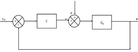
Fig.1. Simple unity feedback control
C ( s ) — 1 L(0) + ^ '(0) +
s
^ "(O) s 2
2!
The ideal form of the PID controller is written as
C ( s ) — kc
The controller C ( s ) can be obtained by Eq. (2) and (3) which is given by Eq. (4).
The controller parameters kc , T 1 and t d are evaluated by matching the coefficients of ‘s’ of Eq. (10) and (11). The following expressions for controller parameters were obtained and given as
C ( s ) = — - Q ( s L
G p 1 - Q ( s )
k c — ^ '(0); T 1 — -k c moreover, t d — ^ y0) (12)
^ (0) 2 k c
The ideal feedback controller C ( s ) is calculated by using Eq. (1), (3), and (4), and which is written in Eq. (5).
as 2 + bs + c e d
----:-----x------;----^
k p ( fs + g ) ( a s + 1) 2 - e-ds
The time delay term e ds in Eq. (5) is approximated by Taylor’s series expansion.
By substituting s = 0 in Eq. (7) and derivative of it,
(0),
^
'(0) and
^
"(0) were obtained as follows:
^
(0)
—
-
D
-
x
D
—
D
, x
N
D
=
D
(
N
2
х
D
-
D
2
х
N)
-
2
D
i
(
N
x
D
-
D
x
N
)
D
3
Where
N
=
c
;
D
=
kpg (2
a
+
d
);
N
=
b
-
cd
;
Where
e
(
t
) represent the error between the set-point and the measurement. The ITAE criterion penalizes the longterm errors whereas the ISE minimizes larger error. The IAE criterion provides controller settings that are between those for the ITAE and ISE criteria.
E. Tuning Parameter
a
selection
D
i
=
k
p
f 2
d
2
)
g
I
a -—
1 +
f
(
2
a
+
d
)
)
f
^2
^
N
2
=
2
\
a
-
bd
+ — l
;
D
2
=
kpf
a
2
-
d
v
)
V
2
)
The PID parameters are calculated by using Eq. (13) – (15) where α was tuning parameter of the controller. The tuning parameter α is chosen in such a manner that the corresponding obtained PID controller should be robust and provide satisfactory results. The designed controller applied to the various process models and the closed-loop performance is compared to the other well-known methods. The following indices were calculated to show the robustness and performance of the present controller. A. Overshoot (%OS) Overshoot is a measure of how much the closed-loop response exceeds the ultimate value following a step change in set point or disturbance. Overshoot is calculated in terms of percentage and denoted as %OS here.
The selection of a suitable tuning parameter
a
is a challenging and tedious task. The tuning parameter selected in such a way that the obtained controller should provide excellent performance and robust. A small value of α give a quick response and shows a better result in the case of load disturbance for stable processes. However, a significant value of
a
provides the stability and robustness of the controller. Maximum sensitivity Ms value is chosen as the performance index to have a clear understanding of a selection of controller tuning parameter
a
, and Ms is defined as
Ms
=
max
1
+
Gp
(
jw
)
C
(
jw
)
Since
Ms
is the inverse of the smallest distance from the Nyquist curve to the critical point (-1, 0) in the Nyquist plot.
Ms
value can also be used to choose a range for the gain margin and phase margin and related to the following relations in terms of
Ms
[32].
GM
>
Ms
Ms
-
1
;
PM
>
2sin
-
1
B. Rise time (tr)
It indicates the speed of the response and it is the time needed to reach first time to ultimate value or set point.
C. Settling time (t
s
)
It is the time required to reach a final steady state value or ultimate value for set-point or disturbance change.
D. Time integral error indices
The performance of the controller indicated by the various time integral error indices like Integral of the absolute error (IAE), Integral of the square error (ISE), and Integral of the time-weighted absolute error (ITAE).
The lower bound of
GM
and
PM
decreases as
Ms
value increases. The minimum value of
GM
is 1.7 and 35 degrees has been recommended
PM
for typical stable processes. Therefore, there are certain limitations of the controller for controlling process and to achieve the desired robust closed loop response [33].
In the present study, the tuning parameter is selected to achieve maximum sensitivity
Ms
value in the range of 1.2-1.8 and shown in Table 1. Since the controller in this range of
Ms
value provides robust and fast closed-loop performance for a stable process.
iae
=
j
e(
(
t
)|
dt
ISE
=
j
e
(
t
)2
dt
ITAE
=
j
t|e
(
t
)|
dt
IV. Simulation Studies
This section showed the comparative studied of present tuning method and various other tuning methods. The simulation studies of various forms of the FOPDT and SOPDT process models have been carried out using the proposed tuning method. Different process models along with the different tuning parameter
a
and their corresponding PID parameters (
kc
,
т
and
r
D ) are shown in Table 1. The present design method provides better performances than the recently developed or published PID design techniques. To show the superiority, the performance of the present PID controller has been
compared with other similar recent developed IMC-PID or direct synthesis PID for both conditions, set point change and load disturbance. The performance of the various controllers is compared in terms of the different performance parameters, settling time (t
s
), rise time (t
r
), overshoot (%OS) and the time integral error indices IAE, ISE and ITAE and given in the subsequent examples.
Example 1.
Second order with time delay (SOPDT) process shown in Table 1, was considered to analyze the performance of the proposed tuning method. This process was also studied by Shamsuzzoha and Lee [34] and Vijayan and Panda [16]. The PID parameters and
Ms
value for the same value of the tuning parameter
a
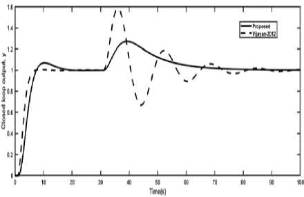
of the present method and the method given by Vijayan and Panda [16] are listed in Table 1. Vijayan and Panda [16] have used two control loops for the control of the process whereas the present method used a single control loop. The closed-loop performance of both controllers is shown in Fig. 2 for both cases set-point as well as disturbance change simultaneously. Fig. 2 clearly shows that the similar behavior for the set point change and Vijayan and Panda [16] shows an oscillatory response in case of disturbance rejection. A second order set-point filter in the form of
fR
=
1/
(
a2s
2 + 2
a
s
+
1
)
is used to remove the excessive overshoot in a set-point change in the proposed method. However, Vijayan and Panda [16] used a first-order set-point filter
fR
=
1/
(
a
s
+
1
)
to remove the overshoot. The performance comparison of both controllers has been made in the term of the various performance indices which are shown in Table 2. The error indices IAE, ISE, and ITAE all are slightly higher in case of set-point tracking but lower in the case of disturbance rejection. The results listed in Table 2 and Fig. 2 clearly illustrated the superiority of the present method over Vijayan and Panda [16]
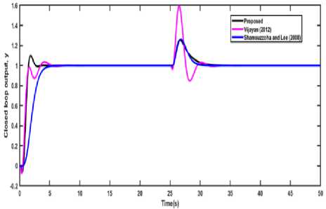
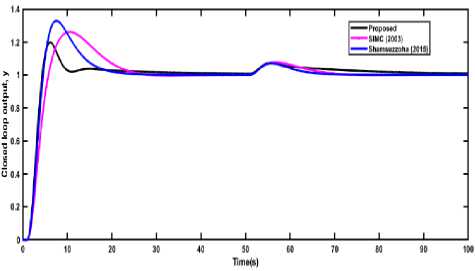
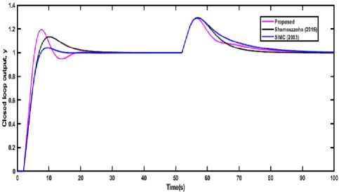
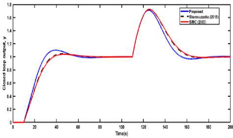
Fig.2. Closed-loop responses of PID control of SOPDT (EX 1) for both set point change and disturbance rejection. Example 2. A second order plus time delay (SOPDT) with inverse response process (Ex 2) listed in Table 2, was considered to analyze the performance of the present PID design method. This process model was selected from the literature and which was also studied by other researchers [10, 16]. The PID cascaded with a lead-lag compensator was used in case of Shamsuzzoha and Lee [10] and a set-point filter of fR = 1 / (0.7044s2 +1.6399s +1) was also used to remove the excessive overshoot. Vijayan and Panda [16] used first-order setpoint filter of fR = 1/(as + 1) . The coefficients of the lead-lag filter are a = 0.2,b = 0.1715 . The present method showed a faster response in the case of the set-point change and settled very quickly as compared to the other two tuning method as shown in Fig. 3. However, Vijayan and Panda [16] give very high overshoot in the case of load disturbance and the proposed method gives a very close response and equal settling time to [10]. The performance criteria in terms of various time domain indices (tr, ts, and %OS) and integral error criteria (IAE, ISE and ITAE) are given in Table 2. This table represents that the proposed method gives lower error indices IAE, ISE, and ITAE than the other two methods in case of the set-point change and provide better than the Vijayan and Panda [16] and similar to the Shamsuzzoha and Lee [10] in case of the load disturbance. Fig.3. Closed-loop responses of the SOPDT (Ex 2) with an inverse response for both set-point and disturbance rejection. Fig.4. Closed-loop responses of PID control of SOPDT (EX 3) for both set point change and disturbance rejection. Example 3. Another SOPDT process model of Ex 3 was selected from Skogestad [35] and Shamsuzzoha (2015) [24], and the proposed PID controller along with other two IMC-PID controllers was used to control the process. The PID parameters and robustness parameter Ms of the all the methods are listed in Table 1. The Ms value of 1.8 was used in the present method, whereas 1.65 was used in the other two methods to select the controller tuning parameter. The closed-loop results were compared with the other methods and shown in Fig. 4. The proposed method shows a faster response, less overshoot and lower settling time as compared to the other methods shown in Table 2 and Fig. 4 in case of set-point change but in the case of load disturbance, the proposed method gives a slightly sluggish response. For set-point change IAE, ISE, and ITAE are lower than another method and in case of disturbance rejection IAE and ISE were nearly equal to the other method. Therefore, the present method is superior to the other two methods.
Table 1. The PID parameters of the different tuning methods and the corresponding robustness (
Ms
)
Examples
Process Model
Method
Tuning parameter
(
a
)
PID parameters
Ms
kc
T
1
T
D
2
e
-
1
s
Ex 1
(
10
s
+
1
)(
5
s
+
1
)
Proposed
0.70
3.17
15.212
3.510
1.35
[16]
0.70
0.44
0.929
6.880
1.41
(
-
0.2
s
+
1
)
e
—
1
'
Ex 2
Proposed
0.20
3.28
1.967
0.484
1.33
(
1
s
+
1
)(
1
s
+
1
)
[16]
0.29
0.75
K
c1
= 2.444
0.415
0.956
2.01
[10]
0.44
3.08
1.640
0.429
1.88
Ex 3
e
1
s
Proposed
0.20
15.24
21.33
1.196
1.80
(
20
s
+
1
)(
2
s
+
1
)
[35]
1.0
10.0
8.0
2.0
1.65
[24]
2.59
9.35
5.59
2.0
1.65
Ex 4
es
Proposed
1.10
3.05
9.780
-0.270
1.78
(
10
s
+
1
)
[24]
4.08
2.53
7.133
0
1.60
[35]
2.0
2.50
10.0
0
1.60
(
—
0.5
s
+
1
)
e
—
1
s
Ex 5
Proposed
0.3
1.73
2.756
0.552
1.80
(
1
s
+
1
)(
2
s
+
1
)
[36]
3.0
0.86
3.0
0.667
1.29
[37]
2.0
1.12
3.030
0.872
1.39
e
—
10
s
Ex 6
(
10
s
+
1
)
Proposed
8.0
0.61
10.265
-0.277
1.26
[24]
9.77
0.51
9.99
0
1.60
[35]
10.0
0.50
10.0
0
1.60
Table 2. Comparison of closed-loop performance of example 1-6 using different methods Set-Point Disturbance
Example
Methods
t
r
(s)
t
s
(s)
%OS
IAE
ISE
ITAE
IAE
ISE
ITAE
Ex 1
Proposed
7.0
15
6.0
3.220
1.530
13.48
4.720
0.84
73.89
[16]
7.0
7.0
1.01
3.058
2.347
5.770
6.860
2.10
101.7
Ex 2
Proposed
1.5
3.0
10.0
0.730
0.421
0.617
0.607
0.10
1.538
[16]
2.5
4.5
1.03
1.153
0.861
1.071
0.934
0.34
1.968
[10]
5.9
5.9
1.01
1.395
1.106
1.135
0.530
0.097
1.170
Ex 3
Proposed
4.2
20
20.0
4.207
2.547
23.15
1.389
0.048
30.0
[35]
5.2
25
26.0
6.295
3.357
44.35
0.832
0.046
8.056
[24]
4.8
20
32.0
5.507
3.095
30.11
0.596
0.029
4.895
Ex 4
Proposed
5.5
18
18.0
4.622
3.201
17.28
3.122
0.519
37.61
[24]
7.0
20
13.0
5.260
3.490
24.40
3.027
0.602
30.72
[35]
7.5
15
4.01
4.637
3.372
11.51
3.890
0.704
50.55
Ex 5
Proposed
4.2
12
32.0
3.619
1.601
18.01
2.513
0.830
16.83
[37]
5.0
12
14.0
3.930
2.960
10.93
2.797
1.077
16.40
[36]
6.2
14
6.0
4.057
3.186
10.36
3.545
1.497
22.81
Ex 6
Proposed
30
60
10.0
20.73
15.76
282.4
17.95
9.299
525.9
[24]
35
60
5.0
21.57
16.69
285.7
19.95
10.51
604.9
[35]
37
60
4.0
21.68
16.86
286.9
20.34
10.73
626.7
Example 4. The first order with time delay (FOPDT) process (Ex 4) is chosen from the literature and which was also studied by Shamsuzzoha (2015) [24] and Skogestad [35] for the control purpose. In the present study, the FOPDT process model was converted to SOPDT by time delay approximation using Taylor’s series as follows:
G
p
dd —s — k - ds _ke 2 e 2 s
T
S
+
1
T
S
+
1
Skogestad [35] showed that 1/
(
t
s
+
1)
®
e
T
0
S
. This technique of approximation is also used in this study for the conversion of the FOPDT to SOPDT model.
Therefore, the above equation can be simplified
d
S
Gn
=
ke
2 /
1
1
+ — I
(
t
s
+
1).
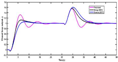
p This technique of approximation was used in the present method and the required process model Gp = e2SS / (10s +1)» e-1S / (s +1)(10s +1) was approximated. The PID controller parameters were calculated for the SOPDT process model and these tuning parameters were used to control the original FOPDT model. The closed-loop results of the present method were compared with another IMC based PI/PID controller listed in Table 1. The controller parameters along with individual Ms value of all the controller are also given in Table 1. The performance comparisons in terms of various performance parameters such as tr, ts, %OS IAE, ISE and ITAE for both the cases set-point as well as disturbance rejection are listed in Table 2. The proposed method has a better closed-loop response than the other two methods in both cases set-point tracking as well as disturbance rejection as shown in Fig. 5. Table 2 shows that the present method has faster response and lower settling time with slightly greater overshoot. The error criteria IAE, ISE, and ITAE are lower or comparable in both cases, setpoint change and disturbance change. The closed-loop results show that the proposed method is superior to the other two methods. Fig.5. Closed-loop responses of PID control of FOPDT (EX 4) for both set point change and disturbance rejection. Example 5. A SOPDT process model having inverse response characteristics was chosen from the recently published paper Saxena and Hote [36] and [37]. The tuning parameter a = 3 is set in the present method based on the Ms = 1.8 value and the corresponding controller parameters along with other methods are shown in Table 1. A setpoint filter fR = 1 (4as +1) was used in the present method to remove the undesirable overshoot. Fig. 6 shows the closed-loop responses of the various tuning methods. The proposed method has faster response lower settling time, than the other two methods in both cases, set point change and the disturbance rejection. The performance in terms of the various time domain indices and integral error criteria of the different tuning methods are listed in Table 2. The error criteria IAE and ISE both are lower than the other methods for the set point as well as disturbance change. However, the ITAE was comparable in case of set point change and slightly greater for the disturbance change. The results from Fig. 6 and Table 2 show that the proposed method is comparable to another tuning method. Fig.6. Closed-loop responses of the SOPDT (Ex 5) with an inverse response for both set-point and disturbance rejection.
Example 6.
The first order with a time delay (FOPDT) is chosen with a high value of time delay. This process model was also studied by Shamsuzzoha (2015) [24] and Skogestad [35]. A similar technique of example 4 was applied here to convert the FOPDT to SOPDT process model. The PID controller is designed by the proposed method for the SOPDT process, and it is applied to the original FOPDT process. The controller parameters of the tuning methods are given in Table 1. Fig. 7 shows the comparisons of the closed loop response of the different tuning methods for the setpoint change and load disturbance. The proposed method gives a faster response for both the servo problem as well as a regulatory problem. Table 2 shows the performance indices in terms of the various error criteria IAE, ISE and ITAE, and in both cases servo and regulatory problems the proposed method gives better results.
Fig.7. Closed-loop responses of PID control of FOPDT (EX 6) for both set point change and disturbance rejection. V. Conclusions PID controller design using the direct synthesis method was developed and successfully applied to the six different forms FOPDT and SOPDT with/without inverse response process models. Maclaurin series was used efficiently to convert the designed controller into an ideal form of PID. A simple method of selection procedure of tuning parameter α was proposed in this study. The Ms value was selected in the range of 1.2-1.8 to obtain fast and robust performance. The proposed controller was the simulated closed-loop results are compared to different similar tuning methods. The simulation study shows that the proposed method is better than the other previous similar tuning rules. Acknowledgment The authors are grateful to the department of chemical engineering, Indian Institute of Technology (BHU) for providing lab to conduct the research work and Ministry of Human Resource Development, India (MHRD, India) for providing financial support.
References PID controller design for SOPDT using direct synthesis method
- K. J. Åström and T. Hägglund, "The future of PID control," Control engineering practice, vol. 9, pp. 1163-1175, 2001.
- J. G. Ziegler and N. B. Nichols, "Optimum settings for automatic controllers," trans. ASME, vol. 64, 1942.
- G. Cohen and Coon, "Theoretical consideration of retarded control," Trans. Asme, vol. 75, pp. 827-834, 1953.
- K. J. Ǻström and T. Hägglund, "PID controllers: theory, design, and tuning," Instrument Society of America, Research Triangle Park, NC, vol. 10, 1995.
- B. D. Tyreus and W. L. Luyben, "Tuning PI controllers for integrator/dead time processes," Industrial & Engineering Chemistry Research, vol. 31, pp. 2625-2628, 1992.
- D. E. Rivera, M. Morari, and S. Skogestad, "Internal model control: PID controller design," Industrial & engineering chemistry process design and development, vol. 25, pp. 252-265, 1986.
- C. A. Smith and A. B. Corripio, Principles and practice of automatic process control vol. 2: Wiley New York, 1985.
- A. S. Rao, V. Rao, and M. Chidambaram, "Direct synthesis-based controller design for integrating processes with time delay," Journal of the Franklin Institute, vol. 346, pp. 38-56, 2009.
- A. A. Nasution, J.-C. Jeng, and H.-P. Huang, "Optimal H 2 IMC-PID Controller with Set-Point Weighting for Time-Delayed Unstable Processes," Industrial & Engineering Chemistry Research, vol. 50, pp. 4567-4578, 2011.
- M. Shamsuzzoha and M. Lee, "PID controller design for integrating processes with time delay," Korean Journal of Chemical Engineering, vol. 25, pp. 637-645, 2008.
- V. M. Alfaro, R. Vilanova, and O. Arrieta, "Maximum Sensitivity Based Robust Tuning for Two-Degree-of-Freedom Proportional− Integral Controllers," Industrial & Engineering Chemistry Research, vol. 49, pp. 5415-5423, 2010.
- O. Arrieta and R. Vilanova, "Simple Servo/Regulation Proportional–Integral–Derivative (PID) Tuning Rules for Arbitrary M s-Based Robustness Achievement," Industrial & Engineering Chemistry Research, vol. 51, pp. 2666-2674, 2012.
- K. G. Begum, A. S. Rao, and T. Radhakrishnan, "Maximum sensitivity based analytical tuning rules for PID controllers for unstable dead time processes," Chemical Engineering Research and Design, vol. 109, pp. 593-606, 2016.
- P. R. Dasari, M. Chidambaram, and A. S. Rao, "Simple method of calculating dynamic set-point weighting parameters for time delayed unstable processes," IFAC-PapersOnLine, vol. 51, pp. 395-400, 2018.
- Y. Lee, S. Park, M. Lee, and C. Brosilow, "PID controller tuning for desired closed‐loop responses for SI/SO systems," Aiche journal, vol. 44, pp. 106-115, 1998.
- V. Vijayan and R. C. Panda, "Design of PID controllers in double feedback loops for SISO systems with set-point filters," ISA transactions, vol. 51, pp. 514-521, 2012.
- C.-q. Yin, H.-t. Wang, Q. Sun, and L. Zhao, "Improved Cascade Control System for a Class of Unstable Processes with Time Delay," International Journal of Control, Automation and Systems, vol. 17, pp. 126-135, 2019.
- M. Irshad and A. Ali, "Optimal tuning rules for PI/PID controllers for inverse response processes," IFAC-PapersOnLine, vol. 51, pp. 413-418, 2018.
- C. Grimholt and S. Skogestad, "Optimal PI and PID control of first-order plus delay processes and evaluation of the original and improved SIMC rules," Journal of Process Control, vol. 70, pp. 36-46, 2018.
- M. Chidambaram and N. Saxena, "Refined Ziegler–Nichols Tuning Method for Unstable SISO Systems," in Relay Tuning of PID Controllers, ed: Springer, 2018, pp. 127-150.
- K. G. Begum, T. Radhakrishnan, A. S. Rao, and M. Chidambaram, "IMC based PID controller tuning of series cascade unstable systems," IFAC-PapersOnLine, vol. 49, pp. 795-800, 2016.
- K. G. Begum, A. S. Rao, and T. Radhakrishnan, "Optimal controller synthesis for second order time delay systems with at least one RHP pole," ISA Transactions, vol. 73, pp. 181-188, 2018.
- K. G. Begum, A. S. Rao, and T. Radhakrishnan, "Enhanced IMC based PID controller design for non-minimum phase (NMP) integrating processes with time delays," ISA transactions, vol. 68, pp. 223-234, 2017.
- M. Shamsuzzoha, "A unified approach for proportional-integral-derivative controller design for time delay processes," Korean Journal of Chemical Engineering, vol. 32, pp. 583-596, 2015.
- M. Shamsuzzoha, "IMC based robust PID controller tuning for disturbance rejection," Journal of Central South University, vol. 23, pp. 581-597, 2016.
- M. Shamsuzzoha and M. Lee, "Design of advanced PID controller for enhanced disturbance rejection of second‐order processes with time delay," AIChE Journal, vol. 54, pp. 1526-1536, 2008.
- M. Shamsuzzoha and S. Skogestad, "The setpoint overshoot method: A simple and fast closed-loop approach for PID tuning," Journal of Process Control, vol. 20, pp. 1220-1234, 2010.
- G. Prashanti and M. Chidambaram, "Set-point weighted PID controllers for unstable systems," Journal of the Franklin Institute, vol. 337, pp. 201-215, 2000.
- T. Radhakrishnan, "Performance assessment of control loops involving unstable systems for set point tracking and disturbance rejection," Journal of the Taiwan Institute of Chemical Engineers, 2018.
- M. Chidambaram, "Set point weighted PI/PID controllers," Chemical Engineering Communications, vol. 179, pp. 1-13, 2000.
- D. Chen and D. E. Seborg, "PI/PID controller design based on direct synthesis and disturbance rejection," Industrial & engineering chemistry research, vol. 41, pp. 4807-4822, 2002.
- S. Skogestad and I. Postlethwaite, Multivariable feedback control: analysis and design vol. 2: Wiley New York, 2007.
- A. Anusha and A. S. Rao, "Design and analysis of IMC based PID controller for unstable systems for enhanced closed loop performance," IFAC Proceedings Volumes, vol. 45, pp. 41-46, 2012.
- M. Shamsuzzoha and M. Lee, "IMC− PID Controller Design for Improved Disturbance Rejection of Time-Delayed Processes," Industrial & Engineering Chemistry Research, vol. 46, pp. 2077-2091, 2007.
- S. Skogestad, "Simple analytic rules for model reduction and PID controller tuning," Journal of process control, vol. 13, pp. 291-309, 2003.
- S. Saxena and Y. V. Hote, "Internal model control based PID tuning using first-order filter," International Journal of Control, Automation and Systems, vol. 15, pp. 149-159, 2017.
- Q.-G. Wang, C. C. Hang, and X.-P. Yang, "Single-loop controller design via IMC principles," Automatica, vol. 37, pp. 2041-2048, 2001.
