Power quality improvement for wind energy conversion system using composite observer controller with fuzzy logic

Author: Hemanth Kumar. M.B., Saravanan. B.
Journal: International Journal of Intelligent Systems and Applications @ijisa
Article in issue: 10 vol.10, 2018.
Free access
In this paper, power quality at the distribution system has been examined by introducing an observer based control technique with fuzzy logic controller for wind energy conversion systems with constant wind velocity, for combination of linear, nonlinear loads and with load removal in one of the phases. The power quality improvement, including voltage regulation and reactive power management on the distribution side is achieved and the device used here is a distributed static compensator (DSTATCOM) a voltage source converter(VSC) based power electronic device. The performance is found to be satisfactory with the implementation of DSTATCOM for better voltage regulation with self-sustained DC link voltage at VSC of DSTATCOM. The fuzzy logic controller is used to generate gate pulses to VSC for power quality improvement and is simulated in MATLAB environment and results are studied.
Distributed static compensator (DSTATCOM), fuzzy logic controller, induction generator, nonlinear load, power quality, voltage control, voltage source controller (VSC)
Short address: https://sciup.org/15016537
IDR: 15016537 | DOI: 10.5815/ijisa.2018.10.08
Text of the scientific article Power quality improvement for wind energy conversion system using composite observer controller with fuzzy logic
Published Online October 2018 in MECS
Now a days due to depletion of fossil fuels and intensive greenhouse emission from conventional power generation there is an increase in the penetration of renewable energy resources in the electricity network. Once we interconnect a large number of renewable energy sources and conventional sources at one point it forms an interconnected network also known as grid [1], [2].
Though there are many non-conventional energy sources like biogas, hydro, solar and wind [3] -[5], wind and solar are playing an important role in demand side management, power system stability and the establishment of power pools in the electricity market. In many remote areas still there is an interruption in the power supply and reliability of the power system is less due to the absence of properly distributed generators.
By incorporating several distributed generations, it is possible to improve system stability and reduce additional loading on conventional energy sources. It has been a regular practice to implement induction generators for renewable energy like wind due to its intermittent nature and also robust construction when compared to synchronous generators [6] -[8]. Many authors have proposed and discussed induction machine and synchronous machine modelings. Murthy et al . [9] explained the induction generator modeling and its operation using the software.
The analysis has given the insight about the magnetizing reactance of the machine. Later a new method has been formulated by kalamen et al . [10] for determining the magnetizing inductance of the induction machine. The important role of this magnetizing inductance is to build the voltage and for stability improvement under dynamic load variations.
An induction generator normally operated in three different modes I. Constant power, II. Variable power, and III. Constant speed. By operating the machine in constant power mode, it is possible to achieve better voltage regulation and frequency.
This mode of operation using an electronic load control (ELC) was implemented by Ramirez et al. [11]. Modeling and control of wind generation systems, including storage system based on flywheel were proposed by smoke et al. [12]. When the system is interconnected to the grid, it leads to large voltage and frequency fluctuation, so it is necessary to maintain a constant frequency and better voltage regulation [13].
Voltage source converter (VSC) [14] is a power quality conditioner in the distributed generation system that can be effectively modeled for suppressing power quality problems. The system performance and power quality improvement are governed by the circuit element parameters and the controller algorithm. Many algorithms are reported in the literature and the power quality improvement will vary based on the robustness of its controller. A shunt connected VSC based power quality controller is studied in [15].
A VSC is basically a power electronic device with a capacitor connected in shunt. The voltage regulation can be effectively improved under different loading conditions by implementing VSC.
A unit vector template based controller is proposed [16] for modeling the STATCOM to improve power quality in the case of self-excited induction generators. A genetic algorithm based control is used for modeling STATCOM in [17]. A bi-directional DC-DC power converter with a self-oscillating feature for improving power quality with energy storage is given in [18]. This self-oscillating is a combination of relay and hysteresis current controller.
The switching pulses for STATCOM are generated using a fuzzy logic controller from the rules base. Another advanced control known as the relative rotation speed theory (RRPT) is presented [19]. By using this (RRPT) control algorithm the STATCOM [27] is synchronized with the grid whenever load fluctuations exist in the network.
In this paper, a composite observer control algorithm has been implemented for a wind energy conversion system for power quality improvement using DSTATCOM connected through fuzzy control. The control algorithm is implemented for reactive power support, harmonic reduction, load balancing including voltage regulation. This controller provides better performance of noise reduction due to a reduction in harmonic at the generator terminals.
This paper is organized as follows. Wind turbine modeling is presented in section II,later fuzzy controller connected to WECS is given in section III. After connecting fuzzy controller the simulation results for various cases are discussed in section IV and finally the conclusions are drawn in section V.
-
II. Wind Energy Conversion System Modeling and Controller Design
We know that the wind energy is fluctuating in nature and the power generated also fluctuates with respect to the input. When the wind turbines are installed near to the distribution side [33], then arises the need for power quality improvement [26] and voltage regulation including load balancing. The schematic diagram of wind energy conversion system with DSTATCOM connected through fuzzy logic controller is shown in Fig.1.
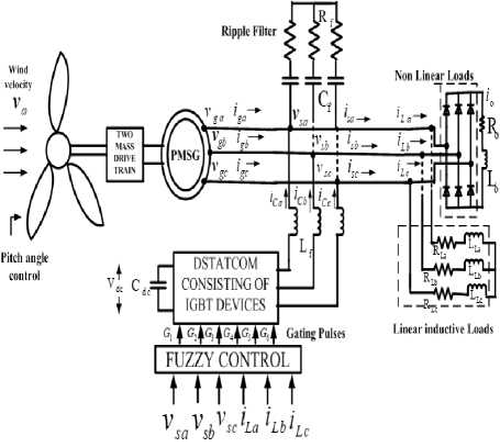
Fig.1. A wind energy conversion system with VSC based Dstatcom with fuzzy controller
The power obtained from the turbine P is a function of power coefficient and wind power and represented by,
P t = ω t T t = C p ( V w , ω t ) P w
where ω give the turbine speed and C is the power coefficient, which is a nondimensional quantity that gives the information about the wind turbine efficiency. Theoretically power coefficient ranges between 0.2 to 0.4 [21]. The generalized expression of power coefficient is given by,
151 V w - 13.635
Cp(Vw,ωt)=0.73 Rωt exp( Vw - 0.003)
Rωt
P w = 0.5 ρ AV ω 3, A = π R 2 (1)
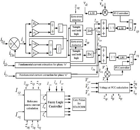
Fig.2. Control technique for generating gate pulses for VSC
The overall control scheme of power quality improvement by using fuzzy logic control is shown in Fig.2.
The power coefficient varies with respect to turbine speed and its characteristic is shown in Fig.3.
0 r y,
—y 0
Based on root locus analysis the constant gains for G1using pole location are
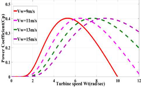
Fig.3. Shows the variation in power coefficient C for variation in turbine speed y
G 1 = [ g 11 g 12 ] T (8)
where “1” is the fundamental component with respect to the load current, i is the deviation observed in harmonic load current and the fundamental load current.
On performing state space analysis the gain values obtained for determining fundamental load current are g11=42,g12= -3.
The system performance can be decided based on whether the system is controllable or observable. To confirm whether the system is controllable or not the matrix S=[G1: P1G1] should be a full matrix. Now, after substituting respective gain values of g11 and g12 the matrix s is given by,
A. Phase and Quadrature Vectors
The voltage available at the point of common coupling (PCC) i.e ( v , v , v ) is used to calculate the unit vectors for in-phase component ( Z ap , Z , Z cp ) and it is shown as below
42 314.28 x ( - 3)
- 3 - 314.28 x (42)
vv sa sb
Z a P т/ , Z bp тл , Z cp
V PCC V PCC
vsc VPCC
From above it is clear that it is a full matrix and nonsingular, so the system is controllable.By this, it is guaranteed that the studied system will generate signals that will be further used for designing control signals. In a similar manner, the system is completely observable if it satisfies the condition of the nonsingular matrix.
Consider the matrix V,
Now it is possible to calculate the quadrature unit vectors from the in-phase components and they are given by,
Q
Q 1 P 1
( - Zbp + Zcp ) (3 Zap + Z bp - Z )
33 , bq = 2^3
( - 3 Z ap + Z bp - Z )
Z cq 2^3
where Q =[1 0] and on solving the matrix operation we get the result as shown below
V =
0 314
it is a nonsingular matrix and
-
B. Fundamental Current Derived from the Load Current
Whenever a nonlinear load is connected to the electrical network it will generate harmonics and due to these harmonics it will introduce additional losses in the system and the performance also gets deteriorated. In this scenario also harmonics are produced which are having m-order with the fundamental and its magnitude is my where y is the fundamental frequency.
The fundamental quantity present in the distorted load current is given by,
.
4 1 = Pi L 1 + G i i e (6)
where therefore observable.
This procedure is used for estimating the fundamental component extraction from the load current in all the three phases and represented as i , i , i .
-
C. Active Power for Estimating Reference Source Current
To determine the active power component magnitude of phase a, sample and hold circuit in conjunction with zero crossing detector with a phase shift of 900 ( Z aq ). The input for the SHC is i and zero cross detector output is used to begin the cycle of operation. By this, the fundamental component of the load current for the phase “a” is determined and represented as ( I ), in a similar manner for remaining phases also the fundamental current components are calculated and represented as
( I Lbp , I Lcp )
The referral source current is determined as,
Isp = I pc + Itpa(11)
where Ipe is the current required at the DC, link and I is the average load current component of phase a and its value is,
Itpa = (I tap + Itbp + Itcp )/3(12)
Now three-phase active reference source currents can be determined from total reference source current in the following ways i * = I z . i *, = I z. . i*
spa sp ap , spb sp bp , spc sp cp
where i s * pa , i * , i s * pc are the active component
-
D. Reactive Power Component for Estimating Reference Source Current
As mentioned in the previous section for calculating the active component of load current, similarly the reactive component for the load current can also be calculated all the phases. Here Z is given as input to the zero cross detector and for sample and hold circuit I as input.
The output from the ZCD is given as a pulse for performing the operation. The reactive component of phase “a” is obtained from the sample and hold and represented as ( I ). In a similar way, reactive components for other two phases also determined and denoted as ( I ) ( I ). The average reactive fundamental component of the load current is given by,
I tqa = ( I taq + I tbq + I Lcq V3 (14)
The total reference reactive source current is given by
Till now we have determined reference currents, the error is found by calculating the difference between reference currents and the actual measured currents.This error is compared with the rule base data and gate pulses are generated from the fuzzy logic controller which is further set for DSTATCOM operation.
-
III. Fuzzy Control Strategy
There are several current control strategies and among them hysteresis current controller[22] has a fast response but has the disadvantage of the current distortions in the output and high switching losses. The switching losses can be reduced by introducing fuzzy control logic [23,29]. This fuzzy logic is widely used in almost all fields of engineering. In this paper, it is used for improving power quality, voltage balance through reactive power management[24]. The current error is sent through a rule base and after performing defuzzification it generated gate pulses for DSTATCOM. A fuzzy controller has following stages of fuzzification, rule base, evaluation of rules and defuzzification [25,31,32]. Always error is considered as the control inputs and it is further transformed to fuzzy variables. In the rule base the fuzzy sets are(AND, NOT, OR). In the final stage i.e in defuzzification, the variables are converter to real values. The purpose of the database is to store membership values. The controls that are necessary are stored in the rule base which will be used by the evaluator. The fuzzy rule base is shown in Table.1.
Table 1. Fuzzy Rule Base
|
Change in error( A e) |
|||||||
|
Error(e) |
PH |
PM |
PS |
Z |
NS |
NM |
NH |
|
PH |
PH |
PH |
PH |
PH |
PM |
PS |
Z |
|
PM |
PH |
PH |
PH |
PM |
NS |
Z |
NS |
|
PS |
PH |
PH |
PM |
PS |
Z |
NS |
NM |
|
Z |
PH |
PM |
PS |
Z |
NS |
NM |
NH |
|
NS |
PM |
PS |
Z |
NS |
NM |
NH |
NH |
|
NM |
PS |
Z |
NS |
NM |
NH |
NH |
NH |
|
NH |
Z |
NS |
NM |
NH |
NH |
NH |
NH |
I sq = I qc - I tqa (15)
where Iqc is required for maintaining generator voltage The total reactive component is used to determine individual reactive phase components by utilizing quadrature voltage vectors( Z , Z , Z ) ,
i* = I Z . i*, = I Z, , i*
sqa sq aq , sqb sq bq , sqcsq
Zcq
From eq (13) and eq (16) the overall reference current is expressed as, i * = i * + i * , i = i *+ i * ,i i * = i *
sa spa sqa ,sb spb sqb ,sc spcsqc
-
IV. Simulation Results and Discussion
The proposed control algorithm is implemented in the Matlab environment and tested for different load conditions for improving the power factor, voltage regulation and load balancing.The system data and the electrical parameters are given in Appendix-A. In this paper, a hysteresis droop controller is also implemented for obtaining a quick response with a dynamic variation on the load side. The results show better improvement in the %THD compared to other algorithms.
-
A. Performance of WECS with Linear Load and Steady Operating Conditions
When a linear load is connected the source current and the load current are not having much distortion so load current follows the source current with very less
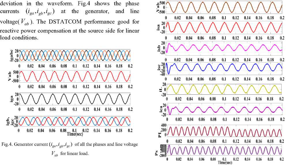
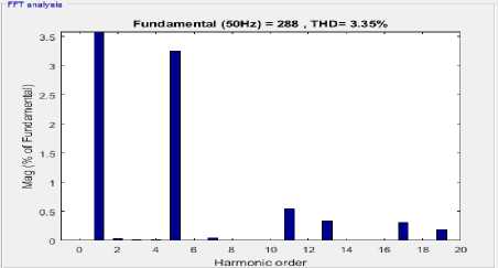
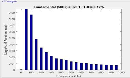
B. Effect of D Statcom with Linear Load (c)
Fig.5. D Statcom performance under linear load: (a) and (b) shows the harmonic spectra for source current and voltage. (c) ( i , i , i ) with
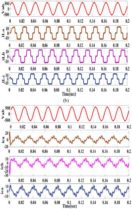
Now, after connecting DSTATCOM the voltage and current waveforms are shown in Fig.5. The waveforms of currents ( i , i , i ) at the source side, harmonics at phase a, source current at phase “a”, load current for phase “a” with PCC, compensating current( i ca ). The source and load powers are also shown in Fig.5.From Fig.5 it is clear that the pf is leading at the supply terminals as it absorbs reactive power for voltage regulation. The %THD at source current and voltages are 3.35% and 0.12% respectively.
(a)
(b)
Vab and iL , ica , PLandPS
-
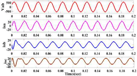
C. D Statcom P erformance with Load Removal
When the load dynamics occurs, i.e. change in the magnitude of the load in any one phase or more than one phase. The dynamics can also due to the removal of loads also, here in this case load is removed in phase b. Fig.6. shows the source current ( i , i , i ) and load currents ( i , i , i ) with the voltage at PCC for linear loads. The dc link voltage, source current for phase b, load current for phase b and compensated current is shown in Fig.6.
(a)
(b)
(c)
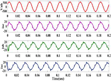
Fig.6. (a)line voltage V and source current ( i , i , i ) (b)line voltage V at source side with load currents ( i , i , i ) at respective phases (c)line voltage v and source current( i ) in phase “b”,load current( i ) in phase “b”,compensating current( i ) in phase “b”.
-
D. Performance of D Statcom under nonlinear loads for voltage regulation
Now a nonlinear load is connected and the performance of DSTATCOM is observed. Fig.7. shows generator current( iga , igb , igc ) and line voltage ( V gab ) for the nonlinear load. So the DSTATCOM is able to suppress the harmonics at the source side for nonlinear loads effectively.
(a)
(c)
Fig.7. Performance of D Statcom for non linear load case: (a) line voltage Vab and source current ( isa , i , isc ) (b) line voltage Vab at source side with load currents ( i , i , i ) (c) line voltage V and compensating current
-
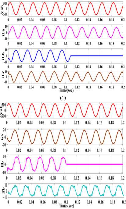
E. Performance of D Statcom for Non Linear Load Dynamics
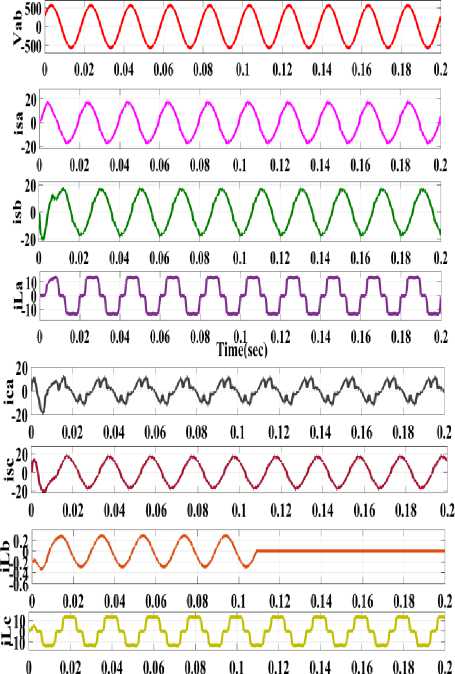
Fig.8. shows the source current for all the phases with their magnitudes, load currents( i ) and also the compensator currents( i са ) are also shown in Fig.8. It is clear that the PCC voltage is maintained at desired values and also with better harmonic suppression.The power factor is also leading due to the supply of reactive power into the system for voltage regulation.
When the load is removed in one of the phases the source currents are balanced as shown in Fig.8. So, after performing several tests the control technique is giving better results for power quality improvement with the application of DSTATCOM for linear and nonlinear loads including system dynamics.
Time(sec)
Fig.8. D Statcom performance under nonlinear load for load removal in phase “b” represents compensating current i for phase “a”source currents ( i ) ,and load currents ( ii ) sc lb , lc
-
V. Conclusion
In this paper the performance of DSTATCOM consisting of VSC based is being studied for power quality improvement, reactive power compensation, harmonics at the source side and load side under different loading conditions through a fuzzy logic controller is satisfying the IEEE standards. The fuzzy controller generates gating pulses by calculating the error and maintain the voltage level at PCC.The results have shown the satisfactory operation for the proposed technique. Here the voltage at the DC link of the STATCOM is also regulated to match with the reference value. The operating time is also less when compared to other control algorithms and it effectively achieves reactive power management under dynamic loading conditions. The controller is showing better results for load removal also and the variation in the source, load and compensating currents are observed simultaneously under dynamic conditions.
Appendix A System Parameters
|
Three phase linear R-L load |
3.5 KVA,0.9 lagging PF |
|
Non linear loads: Full bridge dide rectifir |
R o =3O Q ,L o =1OOmH |
|
Ripple filter Cf |
10 H F |
|
Switching frequency |
6KHz |
|
DC-link PI controller gains, |
K dp = 0.95 K di = 0.15 |
|
Cut off frequency of LPF for load active and reactive component |
8 Hz |
|
Interfacing inductor |
4.0mH |
|
Dc link capacitor |
2350 h F |
|
Ripple filer Rf |
5ohm |
|
Fundamental frequency |
314.159 rad/s |
|
Generator PI controller gains |
Kqp = 0.95 K qi = 0.15 |
|
Fundamental frequency |
314.159 rad/s |
Acknowledgment
The authors would like to thank School of Electrical Engineering, VIT University, Vellore, India for constant support to carry out the research work.
References Power quality improvement for wind energy conversion system using composite observer controller with fuzzy logic
- D. M. Tagare, Electric Power Generation: The Changing Dimensions.Hoboken, NJ, USA: Wiley, 2011.
- C. Bhattacharjee and B. K. Roy, “Advanced fuzzy power extraction control of wind energy conversion system for power quality improvement in a grid tied hybrid generation system,” IET Gener. Transm. Distrib., vol. 10, no. 5, pp. 1179–1189, 2016.
- Y. Fan, G. Hu, and M. Egerstedt, “Distributed Reactive Power Sharing Control for Microgrids with Event-Triggered Communication,” IEEE Trans. Control Syst. Technol., vol. 25, no. 1, pp. 118–128, 2017.
- L. Wang, C. H. Chang, B. L. Kuan, and A. V. Prokhorov, “Stability Improvement of a Two-Area Power System Connected with an Integrated Onshore and Offshore Wind Farm Using a STATCOM,” IEEE Trans. Ind. Appl., vol. 53, no. 2, pp. 867–877, 2017.
- A.Kulmala, S. Repo, and P. Jarventausta, “Coordinated voltage controlin distribution networks including several distributed energy resources,”IEEE Trans. Smart Grid, vol. 5, no. 4, pp. 2010–2020,Jul. 2014.
- T. Bogodorova, S. Member, L. Vanfretti, and S. Member, “Model Structure Choice for a Static VAR Compensator under Modeling Uncertainty and Incomplete Information,” vol. 3536, no. c, pp. 1–9, 2017.
- S. Gao, G. Bhuvaneswari, S. S. Murthy, and U. Kalla, “Efficient voltage regulation scheme for three-phase self-excited induction generator feeding single-phase load in remote locations,” IET Renew. Power Gener., vol. 8, no. 2, pp. 100–108, Mar. 2014.
- B. Singh, S. Jain, S. Gupta, and S. Tiwari, “Series active filter based voltage controller for an isolated asynchronous generator,” in Proc. IEEE Int. Conf. Power Electron., Drives Energy Syst., 2012, pp. 1–6.
- S. S. Murthy and R. K. Ahuja, “Design and analysis of three phase selfexcited induction generator usingMATLAB graphical user interface based methodology,” in Proc. Int. Conf. Power, Control Embedded Syst., 2010, pp. 1–5.
- L. Kalamen, P. Rafajdus, P. Sekerak, and V. Hrabovcova, “A novelmethod of magnetizing inductance investigation of self-excited induction generators,” IEEE Trans. Magn., vol. 48, no. 4, pp. 1657–1660, Apr. 2012.
- J. M. Ramirez and M. Emmanuel Torres, “An electronic load controller for the self-excited induction generator,” IEEE Trans. Energy Convers., vol. 22, no. 2, pp. 546–548, Jun. 2007.
- G. Cimuca, S. Breban, M. M. Radulescu, C. Saudemont, and B. Robyns, “Design and control strategies of an induction-machinebasedflywheel energy storage system associated to a variable-speed wind generator,” IEEE Trans. Energy Convers., vol. 25, no. 2, pp. 526–534, Jun. 2010.
- R. Mitra, A. K. Goswami, and P. K. Tiwari, “Voltage sag assessment using type-2 fuzzy system considering uncertainties in distribution system,” IET Gener. Transm. Distrib., vol. 11, no. 6, pp. 1409–1419, 2017.
- A. C. Moreira, H. K. M. Paredes, W. A. de Souza, F. P. Marafao, and L. C. P. da Silva, “Intelligent Expert System for Power Quality Improvement Under Distorted and Unbalanced Conditions in Three-Phase AC Microgrids,” IEEE Trans. Smart Grid, vol. 3053, no. c, pp. 1–1, 2017.
- B.Singh, S. S. Murthy, and S. Gupta, “Analysis and design of STATCOMbased voltage regulator for self-excited induction generators,” IEEE Trans.Energy Convers., vol. 19, no. 4, pp. 783–790, Dec. 2004.
- B.Singh, S. S. Murthy, and S. Gupta, “STATCOM-based voltage regulator for self-excited induction generator feeding nonlinear loads,” IEEE Trans. Ind. Electron., vol. 53, no. 5, pp. 1437–1452, Oct. 2006.
- R. Karthigaivel, N. Kumaresan, and M. Subbiah, “Analysis and control of self-excited induction generator-converter systems for battery chargingapplications,” intellect.PowerAppl., vol. 5, no. 2, pp. 247–257, Feb. 2011.
- J. A. Barrado, R. Grino, and H. Valderrama-Blavi, “Power-quality improvement of a stand-alone induction generator using a STATCOM With battery energy storage system,” IEEE Trans. Power Del., vol. 25, no. 4, pp. 2734–2741, Oct. 2010.
- W.-L. Chen, Y.-H. Lin, H.-S. Gau, and C.-H. Yu, “STATCOM controls for a self-excited induction generator feeding random loads,” IEEE Trans. Power Del., vol. 23, no. 4, pp. 2207–2215, Oct. 2008.
- Ganesh C, Anupama S, Kumar MBH. Control of Wind Energy Conversion System and Power Quality Improvement in the Sub Rated Region Using Extremum Seeking. Indonesian Journal of Electrical Engineering and Informatics. 2016; 4(1): 14-23.
- A.Ghaffari, M. Krstić and S. Seshagiri, "Power Optimization and Control in Wind Energy Conversion Systems Using Extremum Seeking," in IEEE Transactions on Control Systems Technology, vol. 22, no. 5, pp. 1684-1695, Sept. 2014.
- X. Chen, X. Ruan, D. Yang, W. Zhao, and L. Jia, “Injected Grid Current Quality Improvement for Voltage-Controlled Grid-Connected Inverter,” IEEE Trans. Power Electron., vol. 33, no. 2, pp. 1–1, 2017.
- M. Badoni, A. Singh, and B. Singh, “Adaptive Neurofuzzy Inference System Least-Mean-Square-Based Control Algorithm for DSTATCOM,” IEEE Trans. Ind. Informatics, vol. 12, no. 2, pp. 483–492, 2016.
- Belaidi R Haddouche A guendouz H Fuzzy logic controller based three phase power filter for compensating harmonics and reactive power under unbalanced main voltages. Energy procedia,2012;vol.18,p.560-570.
- Karuppanan P ,Kamala Kanta Mahapatra, PI with fuzzy logic controller based APLC for compensating harmonicand reactive power. Proceeding Conference on control. Communication and power engineering 2010,p.45-49
- A. C. Moreira, H. K. M. Paredes, W. A. de Souza, F. P. Marafao, and L. C. P. da Silva, “Intelligent Expert System for Power Quality Improvement Under Distorted and Unbalanced Conditions in Three-Phase AC Microgrids,” IEEE Trans. Smart Grid, vol. 3053, no. c, pp. 1–1, 2017.
- P. Chittora, A. Singh, and M. Singh, “Performance evaluation of digital filters in distribution static compensator for non-linear loads,” IET Power Electron., vol. 10, no. 14, pp. 1915–1923, 2017.
- Ramji Tiwari, Ramesh Babu. N, "Comparative Analysis of Pitch Angle Controller Strategies for PMSG Based Wind Energy Conversion System", International Journal of Intelligent Systems and Applications(IJISA), Vol.9, No.5, pp.62-73, 2017. DOI: 10.5815/ijisa.2017.05.08
- Kuldeep Singh,"Fuzzy Logic Based Modified Adaptive Modulation Implementation for Performance Enhancement in OFDM Systems", International Journal of Intelligent Systems and Applications(IJISA), Vol.8, No.5, pp.49-54, 2016. DOI: 10.5815/ijisa.2016.05.07
- Hadi Sefidgar, S. Asghar Gholamian,"Fuzzy Logic Control of Wind Turbine System Connection to PM Synchronous Generator for Maximum Power Point Tracking", IJISA, vol.6, no.7, pp.29-35, 2014. DOI: 10.5815/ijisa.2014.07.04
- Hamid Reza Erfanian, Mohammad Javad Abdi, Sahar Kahrizi,"Solving a Linear Programming with Fuzzy Constraint and Objective Coefficients", International Journal of Intelligent Systems and Applications(IJISA), Vol.8, No.7, pp.65-72, 2016. DOI: 10.5815/ijisa.2016.07.07
- Nidhi Arora, Jatinderkumar R. Saini,"Estimation and Approximation Using Neuro-Fuzzy Systems", International Journal of Intelligent Systems and Applications(IJISA), Vol.8, No.6, pp.9-18, 2016. DOI: 10.5815/ijisa.2016.06.02
- Mekalathur, Hemanth Kumar B. "An improved Resonant Fault Current Limiter for Distribution System under Transient Conditions." International Journal of Renewable Energy Research (IJRER) 7.2 (2017): 547-555
