Process Modeling and Simulation of Feedwater Heaters Drains and Vents System of PFBR

Author: T.Lakshmi Priyanka, K.R.S. Narayanan, T. Jayanthi, K.K.KuriaKose, S.A.V Satya Murty
Journal: International Journal of Intelligent Systems and Applications(IJISA) @ijisa
Article in issue: 11 vol.5, 2013.
Free access
Nuclear Power Plants are a complex system and need to be controlled very meticulously to avoid any catastrophe from occurring. The safety and availability of the power plant relies on the human operators both through their ability and reliability to ensure smooth and trouble-free plant operations. Training the operators on normal plant operation, maintenance, fault diagnosis and unforeseen emergencies in the plant helps reduce the latency period of the plant and thus increase the efficiency. Operator Training Simulator has become an indispensable entity in imparting hands on training to these operators. Development of process simulators calls for the process to be designed, modeled and implemented to replicate the real plant in steady state and transient conditions.
PFBR, Operator Training Simulator, Heater Drains and Vents system, Steam Water System, Feed Water Heaters
Short address: https://sciup.org/15010491
IDR: 15010491
Text of the scientific article Process Modeling and Simulation of Feedwater Heaters Drains and Vents System of PFBR
Published Online October 2013 in MECS
Operator training has become an increasing necessity in nuclear power plant industry where its complexity impedes the efficiency, reliability and safety of the plant. Trained personnel are required to operate the plant in steady state conditions as well as under uncalled for events in the plant [1]. Real time process simulators are put to a great use in imparting knowledge on plant operations apart from being used for various purposes like general understanding of the system, design verification and validation, checking and evaluating operating procedures. Real time process simulators require the power plant subsystems to be designed, modeled, implemented and checked for their steady state as well as their dynamic behavior under benchmark transients. This paper discusses the Process modeling and Simulation of Heaters Drains and Vents system in Prototype Fast Breeder Reactor (PFBR).
Most important aspect of Feed water heater performance in nuclear power plants is the precise and reliable level control under all operating conditions. Accurate level control ensures the unit is operating in the area of greatest efficiency (straight condensation) to optimize heat transfer while preventing undo wear and
-
II. Steam Cycle of Prototype Fast Breeder Reactor (PFBR)
Prototype Fast Breeder Reactor (PFBR) is a 500 MWe capacity, pool type reactor utilizing sodium as the main heat transport medium. The reactor core consists of fuel sub assemblies made up of (Uranium, Plutonium) Mixed Oxide Fuel. The heat transport system consists of primary sodium circu it, secondary sodium circuit and steam water system (Refer Fig. 1). Steam Water System adopts Reheat and Regenerative cycle by extracting steam from the HPT exhaust, Intermediate Pressure Turbine (IPT) exhausts and various stages of Low Pressure Turbine (LPT) exhausts to heat the feed water [3,4]. PFBR has 3*100% Low pressure Heaters (LPHs) and two trains of 2*50% units of High Pressure Heaters (HPHs) [5]. Extraction steam for all the LPHs is tapped off from the LPT. These Feed Water Heaters are horizontal, shell and tube type heat exchangers. In the Heaters, the feed water flowing through the tubes is heated by the extraction on the shell side. The extraction steam after heating the feed water gets collected as condensate on the shell side. This Condensate forms the condensate in the heaters. These heaters are also equipped with vents on their shell side to remove non condensable gases from the feed water [6]. A steam water sub system returns back this condensate in heater shells to the Condensate and Feed water systems. This system is the Heaters Drains and Vents System.
-
III. PFBR Operator Training Simulator
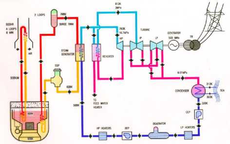
Fig. 1: PFBR Flow Sheet
The platform for simulating the systems comprises of Simulation Computers, Control Panels, Operator Information Consoles, Input/ Output systems, Instructor station, Simulation Network and Power Supply and Distribution system as shown in Fig. 2.
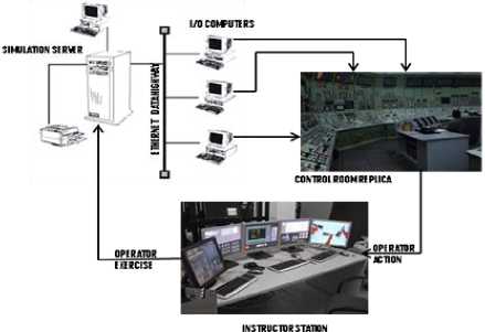
Fig. 2: Hardware Architecture
-
IV. Heaters Drains and Vents System of PFBR
The Heaters Drains and Vents System is one of the subsystems of the Steam Water System in PFBR. The function of the Heaters Drains System is to remove the condensate that has accumulated in the shell side of the Low Pressure Heaters (LPHs) and High Pressure Heaters (HPHs) and cascade the condensate to the next lower pressure heater in the stream and ultimately to the deaerator or the condenser, so as to maintain the level in the condensate in the shell side of the heaters.
In case of Reheaters and HPHs, the normal operating flow path is from the reheaters to Reheater Drain Tank (RDT) from where it is routed to the Reheater Drain Flash tanks (RDFTs). The condensate is then transferred through HPH 6A/6B to HPH 5A/5B and subsequently to the deaerator through the normal drain lines. For the LPHs, the drains from LPH-3 are cascaded normally to LPH-2 and to LPH-1, through the normal drain lines to the condenser. The HP Drain Flash Tank that receives flow from the HPH bank in the case of high level of drains in the heater shells is connected to the main condenser through the vent line and the drain line. The LP Drain Flash Tank that receives the alternate drains from the LPHs in case of high levels in the drain is connected to the condenser by the vent and the drain lines (Fig. 3).
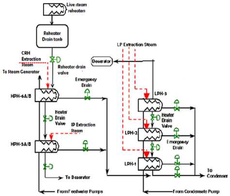
Fig. 3: Heater Drain and Vent System
The function of the Heaters vent system is to remove the non-condensable gases from the feed water heater shells, deaerator and drain cooler. The HPHs 6A/6B and 5A/5B are provided with shell start up vent lines as well as operating vent lines. These lines are routed to the HP drain flash tank. The deaerator startup vent and operating vents are discharged to the atmosphere. Similarly the, LPH-1, 2 and 3 are provided with startup and operating vent valves through which the vents are routed to the condenser at the hood [8].
-
V. Process Modeling
-
5.1 Detailed Study of Design Documents
-
5.2 Identification of Sub Systems
-
5.3 Identification of Main Components of the Sub System
-
5.4 Device and Component Data Collation
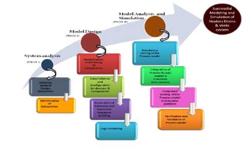
Fig. 4: Steps for Process Modeling
In the simulation tool, the Steam and Hydraulic Networks of the Heater Drain and Vent systems are classified. The steam separated from the flash tanks in the Drain system forms a part of the steam network. The hydraulic network for HPH Drain system comprises of the Reheater Drain system and the HPH drain cascade scheme. The hydraulic network for the LPH Drain system embodies the LP drain cascade scheme. The Vent system for the heaters is designed as a steam network.
Development of networks for the sub system requires modeling of components and devices. Each sub system consists of number of components and devices connected together to represent the process function. The major components to be modeled in HP Drain and Vent system are identified as the Reheaters , the RDT, the RDFTs, HPH 6A/6B and HPH 5A/5B , HPDFT, Deaerator and the Condenser. The components in LPH drain system are the LPH -1, 2 and 3 and the drain cooler and the LP drain flash tank. The devices to be modeled include the connecting pipes, valves, valve actuators, and the level controllers for maintaining the heater levels.
-
5.5 Configuration of Components and Devices
-
5.6 Naming Conventions
-
5.7 Building of Execution Sequence
The system components and devices that were identified are created using the modeling tool and configured using the data collected. With the understanding thus acquired after referring the design and operation notes of the system and the discussions with the design experts enable us to create the steam and the hydraulic networks by connecting the components and the devices configured using the collected data. The networks thus formed are called the mimic diagrams (Fig. 5).
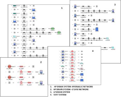
Fig. 5: System Mimic Diagrams
Each process model consists of number of components and devices which need to be identified in a unique and easily identifiable method. For this purpose, the tag numbers for the instruments in the plant are documented and the devices and components in the process model are labeled accordingly to replicate the plant instrumentation.
An Execution Sequence of the process model lists all the components, the controllers and the actuators for the valves represented in the mimic diagrams. A successful build of execution sequence creates the executable file for the process models. Successful building of the execution sequence indicates that there are no glitches in configuring and modeling of the networks.
-
VI. Logic Modeling
-
6.1 Instrumentation
-
6.2 Control of Heater Levels
-
6.2.1 HP heaters and Reheater Drain tank controls
-
Most important aspect of Feed Water Heater performance in nuclear power plants is the precise and reliable level control under all operating conditions. Accurate level control ensures the unit is operating in the area of greatest efficiency to optimize heat transfer while preventing undo wear and tear on the Feed Water Heater and other system components. Operating a Feed Water Heater at levels higher or lower than the design has an effect on performance and ultimately on the net unit heat rate. Conversely, if the level fluctuates to the extremes of the envelope, activation of protective measures to bypass a Feed Water Heater is the minimum response with the outside possibility of a unit trip. Each scenario, in one way or another, negatively impacts the heat rate and profitability of the plant.
Thus level of water in the heater is critical to the efficiency and must be controlled quite closely. Good level control starts with an assessment of the heater instrumentation and control mechanisms and benefits from a basic understanding of heater construction and purpose.
Three level trans mitters in median selection mode are provided for level indication and control for Heaters to generate alarms and interlocks for high and very high levels to take protective action and prevent Turbine from water damage. For LPH-1, three level switches are provided to take the protective action and prevent the turbine from water damage by initiating alarm and protective action for very high level condition. For the RDT, two level transmitters are provided for level monitoring (Fig. 6).
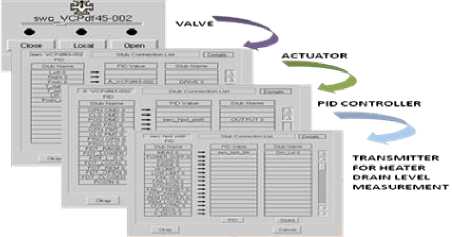
Fig. 6: Control Loop implementation
With accurate level measurement, controls should be able to adjust drain valve position to regulate flow and maintain the proper level for all loads.
Normal level in the HPH-6A/6B is maintained by normal level controller by cascading the drain to HPH-5A/5B through the control valve. The normal level in 5A/5B is maintained by normal level controller by cascading the drain to deaerator through control valve. In case of high level of drain the HPH-6A/6B and 5A/5B is controlled by high level controller through the control valve in the alternate drain line to HP drain flash tank and thus to the condenser.
Normal level in RDT is maintained by draining to the RDFTs. If level in RDT reaches high level, level is controlled by alternate drain control valve to Deaerator.
Under Very High level in HPHs, the respective heater bank (HPH-6A/5A and 6B/5B) isolation is initiated and protective actions of closing the extraction steam isolation valves of the respective heater bank (HPH-6A/5A and 6B/5B) and the RDT normal drain control valves to RDFT-1/2 are also initiated.
-
6.2.2 LP heaters control
-
6.3 Implementation of Level Control Logic
In case of very high levels in any of the heater shells, the heaters are isolated by completely closing the drain valves and the extraction valves of the heaters.
For modeling heater level control, all the main components for instrumentation and control were identified and configured. The interfacing between the components to implement the control loop of Transmitter, Controller, valve actuator and control valve was established using the stub connections in the tool.
The level Controllers connected were tuned for the right match of Proportional gain, Integral time constant and Derivative time constant. The logics for generating alarms and heater isolation were modeled using the logic modeling tool.
-
VII. Integration and Performance Testing of the Process Model
-
7.1 Individual Testing of the Process Model
-
7.2 Integrated Testing 0f Developed Process Model with Other Sub Systems
Integration and Testing of Process Models is the most challenging part of the simulator as it brings out the inadequacies that are overlooked during the individual stage of modeling and testing. The main aspect of Integration and Testing seeks to verify the interfaces between the different process models, cycle time of each process, logical conditions of various components, display of associated alarms and system parameters, correct functioning of process, logics and controls etc. The integrated testing is carried in two phases:
On implementation of control loops for the heaters and the respective logics, the HPH and LPH Drains and Vents system is solely tested for build errors using standalone execution sequence. The rated flow of drains from the higher stages in cascade scheme and the correct functioning of the level controllers as well as the logics are also checked. Any deviation if noticed is tuned and corrected for in this process.
This stage of testing the process model allows integration issues to be localized more quickly and fixed easily.
This stage involves the integration of the process model of the Heater Drains and Vents system with the process models of the other Steam Water sub-systems like the Condensate system, Extraction steam system, Feed Water system, Cold and Hot Reheat System, Main Steam System, Turbine Bypass System etc and all the associated logics and assaying any interfacing issues.
-
VIII. System Testing
-
8.1 Testing under Steady State Condition of Plant
Once all the process models of the reactor sub systems are integrated, the system testing is carried out to verify that the system performs its functions accurately. Non-functional qualities such as the consistency of the process parameters, degree of completeness of the process models as per the design documents are also verified.
The functionality test of the integrated system is carried out in two simulation environments: under steady- state and under transient conditions of the plant.
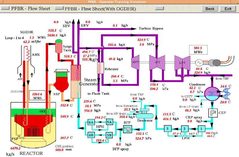
Fig. 7: Steady state condition flow sheet
All the processes in a plant vary with time. Steady state condition is reached when all the process parameters are at their designed values and individual component mass and energy balances are established. Testing under steady state condition is carried out by comparing the performance of the process models with the design data at different power levels of the plant by running the integrated system for long hours. This is done to locate gross errors in modeling of the subsystems as per the design documents as well as to monitor the consistency of the process parameters for checking the reliability of the training tool.
Under the steady state condition, the heater drains and vents operate in the automatic mode. There are no operator initiated actions during steady state. Heater levels are maintained by the inherent balancing characteristics of the cascaded system and upset conditions in the heater level are corrected by proper positioning of the normal level control valves or by operating alternative drain valves automatically. Mass balance on deaerator and condenser is established with the desired flows of the HP drain and LP drain flowing into the deaerator and the condenser respectively. Thus level of feed water in deaerator storage tank and the level of condensate in the condenser hot well are maintained constant. The flow sheet looks as in Fig. 7.
The profiles of heater levels, the drain flows, the Condenser hot well and deaerator level are captured and plotted (Fig. 8). These profiles proved that the heater level controllers were working effectively in maintaining the normal levels and the behavior of the networks was found to be satisfactory.
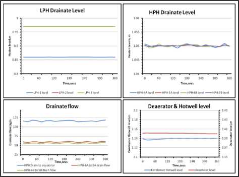
Fig. 8: Profiles for Steady State Condition
-
8.2 Testing under Transient Conditions
Transient condition in a power plant refers to any disturbance introduced into the steady state operation of the plant. The transient or malfunctions in a plant can be tripping of a pump, sudden closure of a valve, tripping of turbine etc.
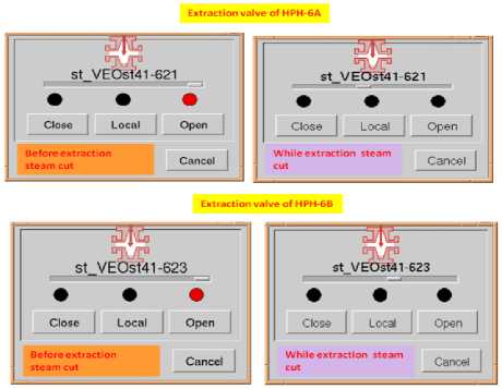
Fig. 9: Control valve positions under no extraction to heaters
For transient testing of the Heaters Drains and Vents system, the response of the system under a benchmark transient like loss of heating in Feed water heaters was studied. Loss of heating in Feed Water Heaters is simulated by cutting off the extraction steam from Cold Reheat Header to the HPH-6A and 6B (Fig. 9). On initiating this event, the heating of feed water did not take place.
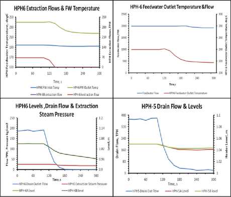
Fig. 10: Profiles for transient condition
Hence, the HPH-6A/B outlet temperature falls and reaches the inlet feed water temperature condition. The level in the HPH-6A/6B also falls and hence drain flow in to the HPH-5A/5B comes down. The level in the
HPH-5A/5B also comes down. To maintain the level in the HPH-5A/5B, the drain flow into deaerator is regulated. Temperature of feed water entering the Steam Generator reduces thus the Secondary sodium outlet temperature of Steam Generator decreases. The feed water controller reduces the Feed water flow entering the Steam Generator.
The corresponding parameters are captured and the trends plotted (Fig. 10). Plotted profiles suggest that process model exhibits desired behavior in accordance with the reference documents and scrutiny by the design experts. The flow sheet looks as in Fig. 11
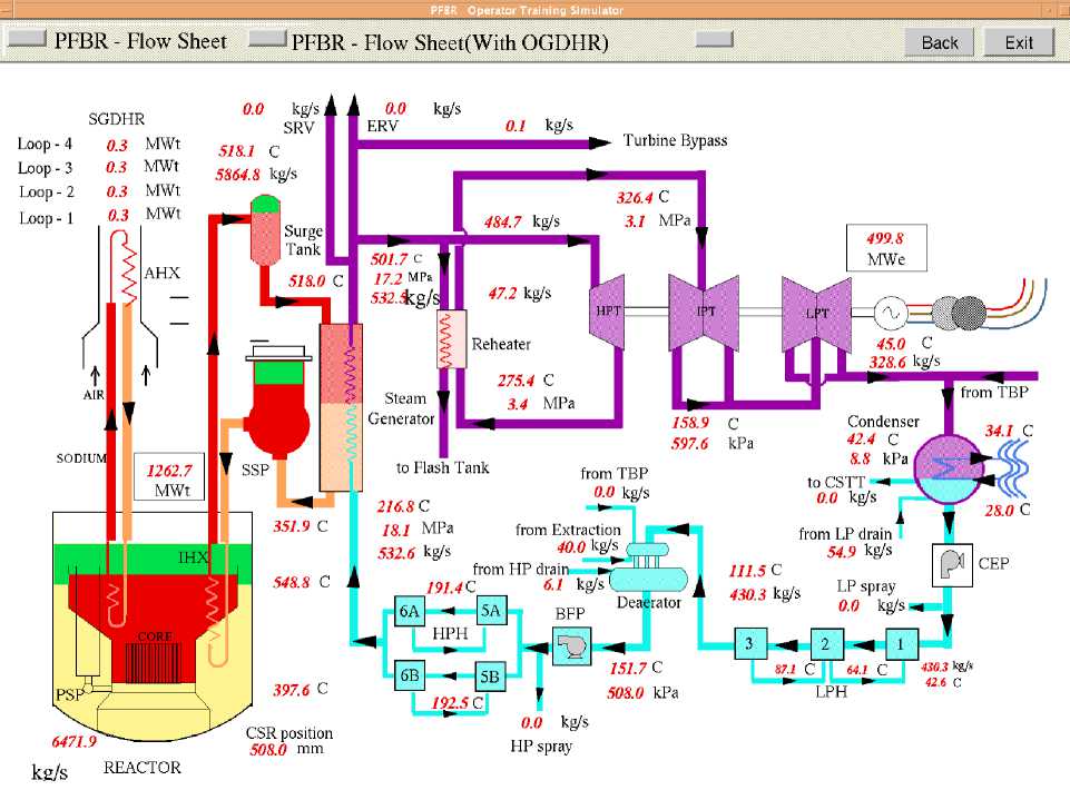
Fig. 11: Flow sheet under transient condition
-
IX. Verification and Validation of Process Models
-
X. Conclusion
Real time simulators have become indispensable in providing a comprehensive solution to the training requirements of plant operators. Human resource with enhanced plant knowledge is an asset to Nuclear Power Plant. Enhanced knowledge to well qualified operators is achieved by implementing an advanced training platform using Full Scope Replica Training Simulators covering various subsystems of the real plant. The operators are trained on various system operating procedures plant start up and shut down operations, steady state and transient conditions of the plant.
Acknowledgement
The authors gratefully acknowledge the support and guidance provided by the colleagues from Reactor Engineering Group, IGCAR.
References Process Modeling and Simulation of Feedwater Heaters Drains and Vents System of PFBR
- Full Scope Replica Type Operator Training Simulator for Prototype Fast Breeder Reactor- T.Jayanthi, S.A.V.Satya Murty, P.Swaminathan
- Level Control Guide for Feedwater Heaters, Moisture Separator/Reheaters, and Other Equipment, EPRI, Palo Alto, CA: 2002. 1003472.
- Operation Notes on Extraction Steam System - PFBR/45000/ON/1050
- Operation Notes on Main Steam, Hot Reheat and Cold Reheat System - PFBR/44000/ON/1050
- Operation Notes on Feed Water System - PFBR/43000/ON/1050
- Operation Notes on Condensate System - PFBR/42000/ON/1050
- Operator Training Simulator, PFBR/08610/DN/1000/Rev A, (2003)
- Operation Notes on Heaters Drains and Vents System - PFBR/43300/ON/1050
- Modeling of Steam Water System Simulator, PFBR 08610/DN/1007/Rev A,(2007)
- Isometric Drawings of Heaters Drains and Vents System- PFBR/43300/DD/2942
