QoS Aware Logical Channel Prioritization under Burst Resource Allocation for Uplink in LTE

Author: Mannu Kumar, Neeti Kashyap
Journal: International Journal of Information Technology and Computer Science(IJITCS) @ijitcs
Article in issue: 8, 2017.
Free access
Long Term Evolution (LTE) is the latest 3GPP (3rd Generation Partnership Project) standard of the Mobile communication system. LTE has been proposed to achieve higher data throughput, lower latency and better quality of service (QoS). In LTE network (n/w), the resource (resource referred to frequency and time domain on the air interface) sharing is one of the major challenging issues and it is one of the key functions to achieve the desired QoS for the different configured data stream. In this context of QoS for LTE n/w, Multiplexing & Logical Channel Prioritization (LCP) is referred. In this paper, we present a brief survey on LCP techniques for the uplink (UL) direction. UL direction referred mobile to n/w communication. A strategy has been proposed for LCP to achieve QoS under burst resource allocation environment. Proposed approach considers the priority of each logical channel configured by evolved NodeB (eNB) during radio bearer (RB) setup/re-configuration.
LTE (Long Term Evolution), LCP (Logical Channel Prioritization), RB (Radio Bearer), eNB (Evolved NodeB), QoS (Quality of Service), MAC (Medium Access Control)
Short address: https://sciup.org/15012669
IDR: 15012669
Text of the scientific article QoS Aware Logical Channel Prioritization under Burst Resource Allocation for Uplink in LTE
Published Online August 2017 in MECS
The 4th generation of mobile communication standard is known as Long Term Evolution (LTE). It is currently being deployed throughout the world. It is the latest deployed mobile communication technology which is successor of 3G technology and has an impressive impact on the world. The collective number of cellular subscriber is leading towards the world population count which is ~ 7 billion [1].
LTE first specification was published under 3GPP Release 8 [2]. The technology used in mobile
Communication has been growing very fast in the last few years and its development is still continuous. Currently, we can see the deployment of LTE n/w all over the world. At the same time new technology is also being researched with the aim of better performance in term of data throughput, latency and QoS for the 5th generation mobile communication [3].
LTE n/w has been optimized for higher data throughput. The maximum data rate is up to 300Mbps for downlink and for uplink, it is up to 75Mbps [4] in Rel-8 standard, LTE-A (Advance) supports even higher speed. LTE is differing with its earlier communication standard at a large extent. The main features of LTE standard can be summarized as follows:
-
• Orthogonal Frequency Division Multiple Access (OFDMA) and Single Carrier Frequency Division Multiple Access (SC-FDMA) are used in DL & UL direction respectively. These techniques allow the sharing of radio resources at the air interface (it is the interface between UE and eNB known as Uu interface).
-
• Transmission Time Interval (TTI) is basically the minimum time period for scheduling. At maximum, a UE can be scheduled in every TTI; duration of a TTI is 1 millisecond (ms). Thus LTE system has fast adaptability with the change of radio conditions.
-
• The core n/w architecture has been simplified to the earlier standards. LTE n/w is completely Internet Protocol (IP) based, means all interfaces between the different n/w nodes are IP based except the air interface.
-
• LTE system provides the better voice quality with Voice over LTE (VoLTE) feature than the earlier standards. Higher codec rate during VoLTE call makes the better voice quality for end users.
-
II. Network Architecture
In this section, we will present the main n/w elements of LTE n/w architecture. Evolution of LTE air interface is referred to as Evolved Universal Terrestrial Radio Access Network (E-UTRAN) and evolution of core n/w is referred to as Evolved Packet Core (EPC). The combined evolution of E-UTARN and EPC together is called
Evolved Packet System (EPS) as shown in Fig. 1.
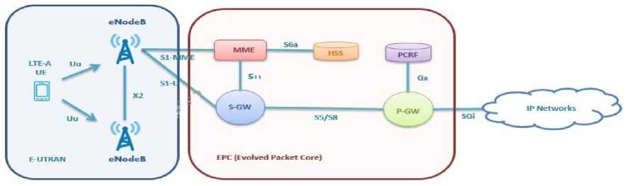
Fig.1. LTE Architecture
Fig. 2 shows the more generalize view of E-UTRAN part of LTE architecture. Communication of E-UTRAN with EPC is either signaling (control plane) or traffic (data plane) as shown in Fig. 2 [5].
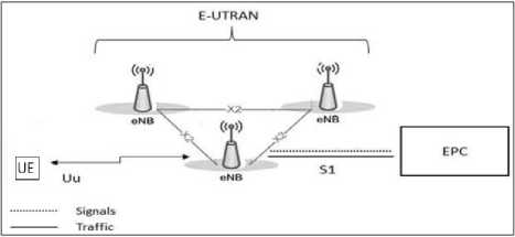
Fig.2. E-UTRAN
By referring the Fig. 1 and Fig. 2, the main component of LTE architecture or EPS architecture as follows:
-
• User Equipment (UE): It is basically a device used by end user for communication. Typically, it is smart phone, data card or hand held communicative device.
-
• E-UTRAN NodeB (eNB): It is the main controller for all air interface related functions. It resides between UE and the core n/w (EPC) and acts like layer 2. The eNB is responsible for radio resource management i.e. resource allocation, traffic scheduling based on the QoS. It also plays a major role in mobility control of the UE in both idle and connected mode [6].
-
• Mobility Management Entity (MME): It is the main component in EPC. It works only in signaling plane. The main function of MME is authentication, security and mobility management [6].
-
• Service Gateway (S-GW): S-GW resides between the eNB & P-GW thus it conveys the traffic between eNB and P-GW. It is used to initiate the paging for the incoming traffic at the UE [6].
-
• PDN Gateway (P-GW): It acts like a gateway between the LTE n/w (EPS) and the external network. It allocates the IP address to the UE during the PDN connection procedure and UE uses this IP to communicate with the other host which is outside of LTE n/w i.e. in external n/w.
-
• Home Subscription Server (HSS): It is basically a repository for all the information related to user profile and different subscription information. It also stores the location of UE when user is in under control of n/w other than home n/w.
-
III. Protocol Stack & Bearer
Likewise, every communication protocol stack, LTE architecture also has two protocols stack i.e. Control plane and User plane as shown in Fig. 3 and Fig. 4 respectively. Fig. 3 and Fig. 4 depict the various protocol layers at different interfaces of control/user plane stack.
-
• Control Plane Stack (C-Plane): It basically provide assistance for the delivery for user traffic ex- link monitoring, mobility management, handover, radio resource allocation etc. During the ongoing traffic session, UE monitor the DL reception quality of the channel and send the Measurement Report (MR) towards the eNB. Based on these MR report eNB takes the decision for handover.
-
• User Plane Stack (U-Plane): It is basically responsible for the delivery of application layer data or simply says user traffic from one node to another node. It deals with efficient, error free and in sequence delivery of user traffic. User traffic mean data initiated from the Application (APP) layer, it may be http request, ftp request or voice call (speech frame generated from the Speech encoder).
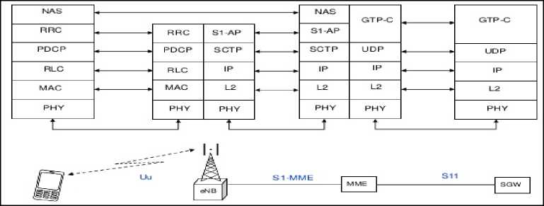
Fig.3. Control Plane Stack
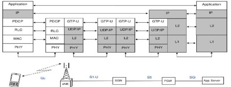
Fig.4. User Plane Stack
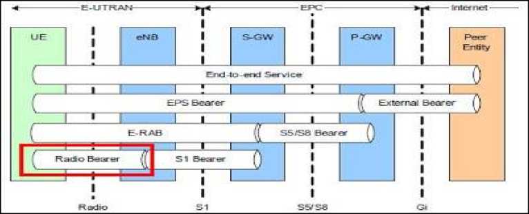
Fig.5. LTE Bearer
-
A. Radio Protocol Stack (Uu)
It is the protocol stack which works on the air interface (Uu) [6] between the UE and eNB. Our study works mainly focus on this radio stack. The U-plane radio stack consists of four layers as shown in Fig. 4.
-
• Packet Data Convergence Protocol (PDCP): The major functions of this layer are header compression, integrity protection, ciphering and re-ordering during handover [7].
-
• Radio Link Control (RLC): The main functions of RLC layer are segmentation/re-segmentation, re-assembly, duplicate detection, re-ordering and ARQ re-transmission [8].
-
• Medium Access Control (MAC): The main functions of MAC layer are resource request
(Scheduling Request), Buffer Status Reporting (BSR), Logical Channel Prioritization (LCP), multiplexing/de-multiplexing and scheduling [9].
-
• PHY: The main functions of PHY layer are modulation & demodulation, frequency and time synchronization, rate matching etc. [10].
-
B. Bearer in LTE Architecture
A bearer is a path through which traffic flow (User/Control plane) between different elements of the LTE n/w as shown in Fig. 5. It is basically a virtual connection between two endpoints.
In our work, we will focus on the EPS bearer and Radio Bearer (RB).
-
• Default EPS bearer: When UE attaches to the n/w (say after power on), it will be assigned a default bearer which remains as long as UE is attached to the n/w. During the establishment of default bearer, UE gets an IP address allocated by P-GW. UE may have multiple default bearers but there exists only one default bearer corresponding to one Access Point Name (APN). Thus a LTE attached UE may have multiple Internet Protocol (IP) addresses each corresponds to one default bearer.
-
• Dedicated EPS bearer: It provide the specific tunnel to one or more specific traffic (i.e. VoIP, video etc.). Each dedicate bearer is associated with a default bearer which we called as Linked EPS bearer and multiple dedicated bearers can be associated with the same default bearer. Both EPS bearer (default and linked dedicated bearer) share the same IP address.
-
• Signaling Radio Bearer (SRB): SRB are used to transfer the signaling/control plane information between the UE & eNB. There exists three SRB i.e. SRB0, SRB1 and SRB2 These SRBs are configured during the RRC connection setup procedure [11].
-
• Data Radio Bearer (DRB): DRB are used to transfer the user plane traffic between UE & eNB. DRB basically is a service provisioned at air interface. It facilitates the QoS at the air interface.
-
C. Bearers Mapping with Logical Channels
-
• There exists three SRB i.e. SRB0, SRB1 and SRB2 and corresponding logical channel identities are 0, 1 and 2 respectively [9].
-
• There exists at max 8 DRB and corresponding logical channel identities are 3 to 10 respectively [9].
-
• Mapping between EPS bearer and DRB is one to one, thus there can exist at max 8 EPS bearer.
-
• EPS bearer ID = DRB ID + 4 and Logical channel ID = DRB ID + 2.
-
IV. Logical Channel Prioritization (LCP) & Buffer Status Report (BSR)
-
A. Logical Channel Prioritization Parameters
eNB signal some parameter to the UE which are used during the uplink scheduling for each logical channel as follows –
-
• Priority: This defines the priority of each configured logical channel where a larger value indicates the lower priority level [9].
-
• Prioritized Bit Rate (PBR): This defines the average bit rate for each logical channel which UE should be able to fulfill to meet the provisioned QoS defined for this channel [9]. Unit of PBR is Kilobytes per second (KBps).
-
• Bucket Size Duration (BSD): This defines the upper time limit for continuous accumulation of data for each logical channel. This parameter is used to avoid starvation for lower priority logical channel [9]. Unit of BSD is in milliseconds (ms).
The range of parameter defined for each logical channel is given in Table 1.
Table 1. Logical Channel Parameters
|
Priority |
1 ~ 16 |
|
Prioritized Bit Rate (PBR) |
0KBps ~ 2048KBps |
|
Bucket Size Duration (BSD) |
50ms ~ 1000ms |
B. Logical Channel Prioritization Algorithm
The UE contains a variable B L for every configured logical channel L. Variable B L is initialized to zero when the respective logical channel is configured. It is incremented by the PBR for each TTI (Transmission Time Interval) but the value of BL cannot exceed beyond the defined bucket size for the particular logical channel L. If the value of BL is greater than the defined bucket size, then it is set to defined bucket size only. The upper bound of bucket size for a logical channel L is equal to PBR × BSD.
Fig. 6 shows the pictorial presentation of Logical Channel Prioritization. It is showing how the data is picked up from the different logical channel by considering the grant provided for the current TTI and configured priority of each channel.
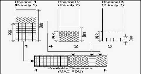
Fig.6. Logical Channel Prioritization
-
C. Buffer Status Report (BSR)
As in the LTE n/w, grant allocation is totally controlled by eNB, so whenever there is a new transmission of data it is necessary to notify the eNB about the amount of data waiting for transmission in the buffer so that eNB can allocate the necessary grant for the transmission of available data. BSR reporting is controlled by eNB with configuration of two timers as given below:
-
• RetxBSR-Timer: When a BSR is included in the
MAC PDU, this timer is started. It is restarted for every uplink grant received by UE provided that it is already running. If the timer expires and UE has the data available for transmission, then BSR is triggered. It is used to avoid the stall situation when UE think it has sent the BSR to eNB and actually eNB did not receive it. Possible range of timer value is 320ms ~ 10240ms.
-
• PeriodicBSR-Timer: When a BSR is included in the MAC PDU, this timer is started and at the expiry of the timer a BSR is triggered again. Possible range of timer value is 5ms ~ 2560ms.
When a BSR has been triggered and UE has uplink grant for this TTI then BSR is included in the MAC PDU otherwise a scheduling request shall be triggered [9].
-
D. Scheduling Request (SR)
The scheduling request is used by UE to request the uplink resources for the new transmission. At starting initialize the SR_COUNTER to 0. Below is the SR procedure [9] –
-
• If UE has no valid Packet Uplink Control Channel (PUCCH) resources for SR request, then initiate a Random Access procedure (RACH).
-
• Else if UE has valid SR resources-
- o If SR_COUNTER < dsr-TransMax.
-
■ Increment SR_COUNTER by 1.
-
- Send SR on PUCCH.
-
o Else initiate the RACH procedure.
Parameters configured by the n/w which controls the scheduling request procedure as given below:
-
• dsr-TransMax: This defines the maximum number of times SR request can be sent before triggering the RACH procedure. Maximum value of this attribute is 64.
-
• SR Periodicity: After transmitting SR on PUCCH, if UE doesn’t receive the uplink grant then it re-sends the SR based on the periodicity. Maximum value of periodicity is 80ms.
-
• SR-Prohibit Timer: The timer is used to prohibit
the re-transmission of SR until it expires. Range of this is 0 ~ 7 in multiple of SR periodicity. Value 0 means no timer is configured, value 1 means one SR period and so on.
-
V. Related Work
-
VI. Proposed Improvements
In this section, we present improvements to the Logical Channel Prioritization in uplink to meet the provisioned QoS. This allows us to find the research direction that will influence the provisioned QoS for the different data stream. In the standard 3GPP approach, the bucket size for each configured logical channel is equal to the product of PBR * BSD except for the logical channel whose PBR is infinity. Under our proposed algorithm, we do not restrict the bucket size value to product of (PBR * BSD) instead we keep increasing size of bucket by PBR amount in every TTI. The standard defined algorithm does not meet the defined QoS for the logical channel under some certain conditions as follows:
-
• If UE is in a condition where eNB is allocating low UL resource grant (i.e. UE is sending less than PBR amount of data in each TTI for a certain time continuously) for Packet Uplink Shared Channel (PUSCH) and there is continuously incoming data from higher layer, then under such situation after a certain time bucket size will be full. Once the
bucket size will be full then standard approach does not consider any more data from higher layer in subsequent TTI and resultant provisioned QoS does not fulfill.
-
• Under certain conditions, existing system will fail to meet the provisioned QoS when RetxBSR timer expires and there is no UL grant.
-
• Existing system does not fulfill the defined QoS when SR request failed even after maximum number of retry (dsr-TransMax).
-
• Under certain conditions, existing system does not able to fulfill the provisioned QoS when PeriodicBSR timer is configured with Max value. To trigger the BSR report, UE wait for the expiry of PeriodicBSR timer. In case, when it is configured with Max value then existing system buffer size will overflow before expiry of this timer provided that data is coming continuously from APP layer.
In our approach we keep accumulating the incoming data from higher layer even though bucket size reaches to product of (PBR * BSD). Thus UE can transmit big chunk of data once it gets the opportunity of larger uplink grant. Thus our approach will provide more flexibility to achieve the QoS under dynamic nature of grant allocation. In our study for accumulation of data, we assume that MAC layer buffer size is very big or infinity. Thus MAC layer buffer capacity directly impacts the flexibility of our algorithm.
-
A. Effect of Bucket size over the provisioned QoS
This section describes how bucket size limitation will affect the provisioned QoS corresponding to a logical channel. Limitation of buffer size will reduce the flexibility of UL data scheduling. Table 2 & 3 shows the bucket size corresponding to each possible value of BSD for PBR rate 8 KBps & 2048 KBps respectively. It shows how many maximum data bytes can be accumulated in the buffer with different value of BSD. It also shows how many bytes are accumulated per TTI. Once the bucket size gets full then no more data will be accumulated further for a logical channel.
Table 2. Bucket size for 8 KBps PBR Rate
|
BSD (ms) |
Data per TTI (bytes) |
Bucket Size (bytes) |
|
50 |
8 |
400 |
|
100 |
8 |
800 |
|
150 |
8 |
1200 |
|
300 |
8 |
2400 |
|
500 |
8 |
4000 |
|
1000 |
8 |
8000 |
Table 3. Bucket Size for 2048 KBps PBR Rate
|
BSD (ms) |
Data per TTI (bytes) |
Bucket Size (bytes) |
|
50 |
2048 |
102400 |
|
100 |
2048 |
204800 |
|
150 |
2048 |
307200 |
|
300 |
2048 |
614400 |
|
500 |
2048 |
1024000 |
|
1000 |
2048 |
2048000 |
|
PBR (KBps) |
Data per TTI (bytes) |
Min Bucket size (bytes) |
Max Bucket Size (bytes) |
|
8 |
8 |
400 |
8000 |
|
16 |
16 |
800 |
16000 |
|
32 |
32 |
1600 |
32000 |
|
64 |
64 |
3200 |
64000 |
|
128 |
128 |
6400 |
128000 |
|
256 |
256 |
12800 |
256000 |
|
512 |
512 |
25600 |
512000 |
|
1024 |
1024 |
51200 |
1024000 |
|
2048 |
2048 |
102400 |
2048000 |
Table 4 shows the data bytes accumulated per TTI, minimum and maximum bucket size corresponding to each PBR rate.
Bucket Size vs BSD
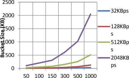
BSD (ms)
Fig.7. Bucket Size Vs BSD corresponding to PBR rate
-
B. Impact of RetxBSR Timer on Bucket size
Table 5. Data Accumulation in Min RetxBSR timer vs. Min Bucket Size
|
PBR (KBps) |
Data accumulation in Min RetxBSR Time (bytes) |
Min Bucket Size (bytes) |
|
8 |
2560 |
400 |
|
16 |
5120 |
800 |
|
32 |
10240 |
1600 |
|
64 |
20480 |
3200 |
|
128 |
40960 |
6400 |
|
256 |
81920 |
12800 |
|
512 |
163840 |
25600 |
|
1024 |
327680 |
51200 |
|
2048 |
655360 |
102400 |
RetxBSR timer is getting start when a MAC PDU containing a BSR is transmitted. Timer range is 320ms ~ 10240ms. Table 5 shows how much data would be accumulated in minimum value of RetxBSR timer (320 ms). It also shows the minimum configurable bucket size corresponding to each PBR rate. This table shows that minimum bucket size is full before expire of RetxBSR timer.
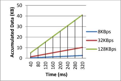
Fig.8. Data accumulated during running of RetxBSR timer
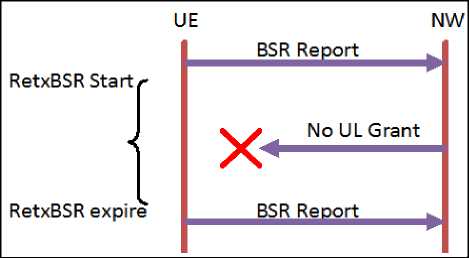
Fig.9. No UL Grant at expiry of RetxBSR
-
VII. Conclusion
This paper has presented an overview of LTE Radio stack and Logical Channel Prioritization in uplink. The proposed algorithm is effective under the burst resource allocation conditions with assumption of large buffer size for layer 2 (MAC). One important characteristic of this effort is that the new protocol builds upon the old one rather than proposing the new solutions, thus this can be adopted easily in the existing system. Another important characteristic is that our proposed methodology fulfills the QoS of application data according to the priority of data under burst resource allocation conditions.
References QoS Aware Logical Channel Prioritization under Burst Resource Allocation for Uplink in LTE
- Brahima Sanou. ICT Facts and Figures. ITU, 2016.
- TS 21.101. Universal mobile telecommunications system (UMTS); technical specifications and technical reports for a UTRAN-based 3GPP system. 3GPP, 2009.
- Fahimeh Rezaei, Michael Hempel, Hamid Sharif. LTE PHY Performance Analysis under 3GPP Standards Parameters. IEEE 2016.
- 3GPP TS 36.401. E-UTRAN architecture description (Release 8).
- Dr. Harri Holma. LTE for UMTS Evolution to LTE-Advanced Second Edition.
- 3GPP TS 36.300. E-UTRA & E-UTRAN overall description (Release 8).
- 3GPP TS 36.323. Technical specification group Radio Access Network; E-UTRA; Packet Data Convergence Protocol (PDCP) specification (Release 8).
- 3GPP TS 36.322. E-UTRA; Radio Link Control (RLC) protocol specification (Release 10).
- 3GPP TS 36.321. E-UTRA; Medium Access Control (MAC) protocol specification (Release 8).
- 3GPP TS 36.201. E-UTRA; Long Term Evolution (LTE) physical layer; General description (Release 8).
- 3GPP TS 36.331. E-UTRA; Long Term Evolution (LTE) Radio Resource Control (RRC); General description (Release 8).
- 3GPP TS 24.301. E-UTRA; Technical Specification Group Core Network and Terminals; Non-Access-Stratum (NAS) protocol for Evolved Packet System (EPS).
- Naila Bouchemal, Nora Izri, Samir Tohme. MAC-LTE Scheduler Modeling and Performance Evaluation in LTE Network. PIMRC, 2014 IEEE 25th Annual International.
- Badri Nayak, A. M. Prasad, Mohamed Niaz. LTE MAC Scheduler Analysis based on QoS Aware Proportional Fair Scheduling Algorithm. IJIRCCE August, 2015.
- Weihong Fu, Qingliang Kong, Weixin Tian, Cheng Wang, Lili Ma. A QoS-Aware Scheduling Algorithm Based on Service Type for LTE Downlink. ICCSEE, 2013.
- A. Balasubramanian, A. Rapaport, W.Liu. VIDEO AWARE LOGICAL CHANNEL BASED SCHEDULING FOR LTE SYSTEMS. InterDigital Communication.
- A. Z. Yonis, M. F. L. Abdullah, "Downlink and Uplink Physical Channels in Long Term Evolution", International Journal of Information Technology and Computer Science (IJITCS), vol.4, no.11, pp.1-10, 2012. DOI: 10.5815/ijitcs.2012.11.01.
- Goudru N.G, Vijaya Kumar B.P, "Performance Analysis of TCP and its Enhancement for Quality of Service in Mobile Wireless Networks in Single Traffic Using Prioritised Hard Handoff (PH2)", International Journal of Information Technology and Computer Science (IJITCS), Vol.8, No.5, pp.88-94, 2016. DOI:10.5815/ijitcs.2016.05.10.
