Quantum software industrial engineering and intelligent cognitive robotics in industry 4.0 as control objects - prototypes of industry 5.0 / 6.0 models: introduction

Author: Tyatyushkina Olga Yu., Ulyanov Sergey V.
Journal: Сетевое научное издание «Системный анализ в науке и образовании» @journal-sanse
Section: Современные проблемы информатики и управления
Article in issue: 1, 2023.
Free access
International project Industry 4.0 (based on intelligent cognitive robotics and Internet of Things (IoT) as forth industrial revolution) together with Quantum Software Engineering and Quantum intelligent control implementations (as the third quantum revolution) open new possibilities for the development “wise Industry 5.0” with practically unbounded information resources (based on a new end-to-end information technology of quantum soft computing and small quantum computers for Quantum Internet of Things). A exible manufacturing system (FMS) involving several robots with different capabilities in a shop oor layout context [1-3]. This use case is composed of an automatic production system and a set of manual workstations where the operator can be assisted by cobotic arms for assembly tasks. In this article we consider autonomous and smarm robots with different intelligent and cognitive levels for Industry 4.0 with the application of embedded quantum intelligent controllers as model background of Industry 5.0.
Cobotic arms, quantum intelligent controllers, sociotechnical cyber-physical robotic systems, industry 5.0
Short address: https://sciup.org/14128092
IDR: 14128092 | UDC: 004.588,
Квантовая программная промышленная инженерия и интеллектуальная когнитивная робототехника в индустрии 4.0 как объекты управления - прототипы моделей индустрии 5.0/6.0: введение
Международный проект Индустрия 4.0 (на основе интеллектуальной когнитивной робототехники и Интернета вещей (IoT) как четвертая промышленная революция) вместе с реализациями Quantum Software Engineering и Quantum smart control (как третья квантовая революция) открывают новые возможности для развития «мудрой Индустрии 5.0». с практически неограниченными информационными ресурсами (на основе новой сквозной информационной технологии квантовых мягких вычислений и малых квантовых компьютеров для квантового Интернета вещей). Гибкая производственная система (FMS), включающая несколько роботов с разными возможностями в контексте планирования работы цеха [1-3]. Этот вариант использования состоит из автоматической производственной системы и набора ручных рабочих станций, где оператору могут помогать коботы-манипуляторы для сборочных задач. В этой статье рассматриваются автономные и интеллектуальные роботы с разным уровнем интеллекта и когнитивных способностей для Индустрии 4.0 с применением встроенных квантовых интеллектуальных контроллеров в качестве модельного проекта Индустрии 5.0.
Text of the scientific article Quantum software industrial engineering and intelligent cognitive robotics in industry 4.0 as control objects - prototypes of industry 5.0 / 6.0 models: introduction
Тятюшкина О. Ю., Ульянов С. В. Квантовая программная промышленная инжинерия и интеллектуальная когнитивная робототехника в Индустрии 4.0 как объекты управления – прототипы моделей Индустрии 5.0/6.0: Введение // Системный анализ в науке и образовании: сетевое научное издание. 2023. № 1. С. 46-94. URL :
Introduction: Industry 4.0 and sociotechnical cyber-physical robotic systems
Mobile robots with diff erent capacities and capabilities ensure transportation tasks. Pick and place operation can be ensured by human operator or robotic arms. Several types of product can be manufactured and augmented reality devices can be used to help the operator in production or maintenance tasks. A digital twin (DT) associated to Human-machine interface (HMI) based on virtual or augmented reality is also present (see Fig. 1).
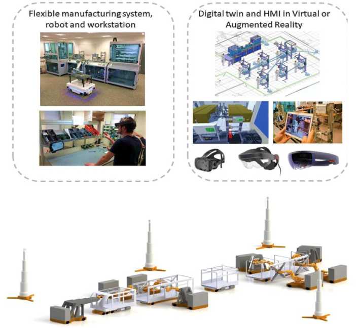
Fig. 1. Flexible manufacturing system and its digital twin [2,3]
The availability of industrial production data in a networked system landscape acts in this background as a technical enabler to increase the relevance of topics, such as AI and data-driven approaches. This further opens up new potentials for optimizing (novel) manufacturing systems, e.g., line-less mobile assembly systems in Fig. 1, which enable agile assembly of large components by leveraging modeling and scheduling systems. The primary objective of utilizing AI at this level is to improve the adaptability of DTs to dynamically changing boundary conditions on the factory and shop floor scale. Typical application subfields with AI-integrated DTs are production planning, production control, and quality control.
As an example, if a new configuration is needed, engineers of the production methods department can design it with the DT (indicated with (1) in Fig. 2).
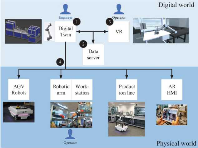
Fig. 2. Digital twin and virtual reality environment [2]
In the context of the Industry 4.0 and of the digital factory, DT and virtual reality represent key technologies to design, simulate and optimize cyber-physical production system and interact with it remotely or in a collaborative way. Moreover, these technologies open up new possibilities which can be involved in the codesign and ergonomics studies of workstations, based on Industry 4.0 components like cobots. In order to satisfy these needs and to create dynamic and immersive virtual environment, it is therefore necessary to combine the capacities of the DT to perform simulation of the production system with the capacities of the immersive virtual environment in term of interactions. This item proposes a co-simulation and communication architecture between DT and virtual reality software, then it presents a use case on a humanrobot collaborative workplace design and assessment [4,5].
As mentioned above, DT is a relevant tool for validating a new factory configuration either in a global point of view by flow simulations or for a specific element by defining a new design. However, DT lacks realism for human-centered design of manufacturing process and workstation. In that sense, virtual reality is a key tool as it can represent the system at scale one and allow instinctive interactions.
Differing from IoT based users, regarding to industrial environments needing real-time data availability and high reliability, the Industrial Internet of Things (InIoT) is the connection of industrial products such as components and/or machines to the Internet [5]. For instance, linking the collected sensing data in a factory with IoT platform, InIoT increases production efficiency with the BD analysis. A typical InIoT is showed in Fig. 3, with wire and wireless connections, increasing value with additional monitoring, analysis and optimization.
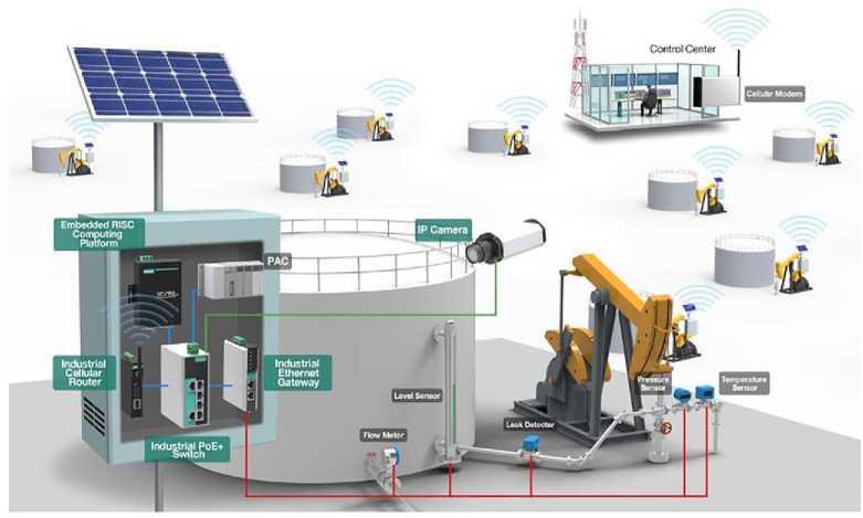
Fig. 3. Typical InIoT network [6]
As a natural evolution of IoT, the Internet of Things (IoT) and Services (IoS) can be seen as the connectivity and interaction of the things creating valuable services and is one of the fundamental bases of the Smart Factory. Manufacturing operations can be shut down by a cyber-attack, therefore, companies have money losses, but the main issue are cyber-attacks targeting systems requiring safety operations and representing a serious risk for the safety of the operators. The cyber-attack could be internal and/or external source. According to Fig. 4, a cyber-attack can come from an internal source such as an operator that physically access to a data port or an external source such as an outside communication channel or also a wireless transmission.
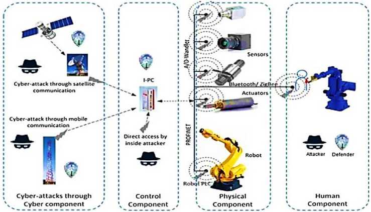
Fig. 4. Cyber-attack routes in an industrial connected manufacturing and logical effect diagram for humanrobot collaboration [6]
Cyber-Physical Systems (CPS) has the potential to change our life with concepts that already emerged, e.g., robotic surgery, autonomous cars, intelligent buildings, smart manufacturing, smart electric grid, and implanted medical devices (e.g., a pace maker in a smaller scale). CPS represents the latest and significative developments of Information and Communication Technologies (ICT) and computer science. CPS is the merger of ‘‘cyber” as electric and electronic systems with ‘‘physical” things. The ‘‘cyber component” allows the ‘‘physical component” (such as mechanical systems) to interact with the physical world by creating a virtual copy of it. This virtual copy will include the ‘‘physical component” of the CPS (i.e., a cyberrepresentation) through the digitalization of data and information [5].
By this, CPS can be assumed as a range of transformative technologies to manage interconnected computational and physical capabilities. CPS embraces smart elements or machines who has the augmented intelligence and ability to communicate each other to make part of planning, unique or non-repetitive tasks. These smart elements, for instance, can control the needs of workpieces, alter the manufacturing strategies for the optimal production, choose (if already exists) or find a new strategy all by themselves.
These elements will build their own network. In other words, the CPS core is the embedded system to process information about the physical environment. This embedded system will perform tasks that were processed by dedicated computers. CPS model can be described as a control unit with one or more microcontrollers, controlling sensors and actuators that interacts with the real world and processes the collected data. A communication interface will enable this embedded system to exchange data with the cloud or with other embedded systems. CPS is associated with the IoT concept.
The paradigm of Industry 4.0 in manufacturing systems has another dimension between horizontal and vertical integration considering the entire product lifecycle. This kind of integration is based on vertical and horizontal integrations. In a vision of holistic digital engineering, as the natural flow of a persistent and interactive digital model, the scope of the end-to-end digital integration is on closing gaps between product design and manufacturing and the customer, e.g., from the acquisition of raw material for the manufacturing system, product use and its end-of-life.
The phase of end-of-life product contains reusing, remanufacturing, recovery and disposal, recycling, and the transport between all phases. The relationship between the three types of integration on a manufacturing system, considering vertical integration as the corporation(s), horizontal integration between corporations, and end-to-end integration linking design, production and logistics as an example.
Manufacturing paradigm is shifting rapidly production from mass towards customized production, requiring robots, for instance, as a reconfigurable automation technology. The impact on the production systems of the manufacturing companies is that this trend leads to the production adaptation for a wider product variation, focusing ideally on batch size one. Nowadays, to reach the flexibility demanded level, robots are essential on production systems. Towards that, abilities on computing, communication, control, autonomy and sociality are achieved terms when combining microprocessors and Artificial Intelligence (AI) with products, services, and machines to make them become smarter.
Robots with AI, adaptive and flexible, can facilitate different products manufacturing and consequently providing decreasing production costs. In addition, a robot also can be seen as one of the forms of AI. Processes such as product development, manufacturing and assembling phases, are processes that adaptive robots are very useful on manufacturing systems. It is important to refer that fully autonomous robots make their own decisions to perform tacks on a constantly changeable environments without operator’s interaction.
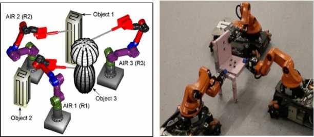
Dirty or hazardous industrial applications on unstructured environments can be improved by an Autonomous Industrial Robot (AIR) or multiple in a close collaboration. It was presented a multiple autonomous robot’s collaboration approach in Fig. 5a, consisting on robots with different capabilities performing gritblasting and spray painting.
(a) (b)
Fig. 5. Autonomous robots’ manipulators with different capabilities (a) Autonomous industrial robots performing grit-blasting or spray painting; (b) Assembly configuration robots [6]
With the deployment of multiple autonomous industrial robots working as a team, it’s possible to have a larger range of manufacturing applications. Other approach in multi-robot systems can be seen in Fig. 5b during a sequence of collaborative assembly operations, dealing with robot configurations to grasp assembly parts and build complex structures such as a chair.
Cyber-Physical Production System. The integration of Industry 4.0 components and the development of digital technologies can lead to more efficient and more flexible processes in order to manufacture a variety of high-quality products with a reduction of cost and time, giving a significant competitive advantage. When gathered, flexible manufacturing systems, industrial internet of things, simulation, big data analysis, and cloud manufacturing, lead to a Cyber-Physical Production System (CPPS).
Several authors demonstrate the benefits of CPPS deployment within Industry 4.0 thanks to more relevant analysis and management. CPPS including a digital twin is a very powerful tool to aim for the best possible performance of a production system but it can hardly be fully autonomous. Human interventions are frequently needed to control and run the production system and also to design or re-design the process. For that reason, there is a strong need of human to CPPS interfaces.
The case study is based on the presented CPPS and particularly focusing on the manual workstation where an operator is working in collaboration with a robotic arm (UR 10) to assemble a subassembly of a children’s bike (see Fig. 6).
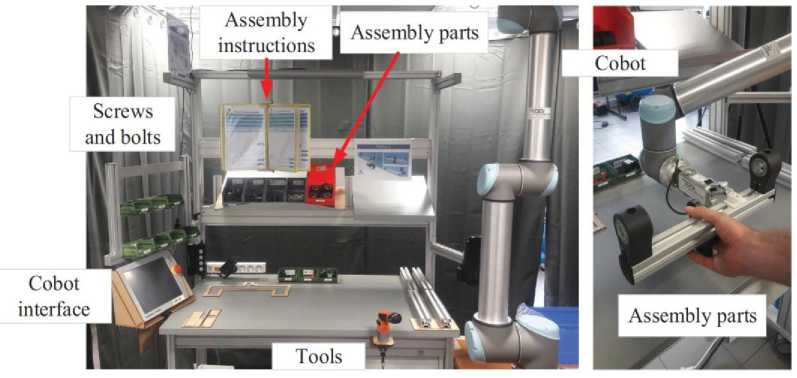
Fig. 6. Workstation with cobotic arm
The assembly process at this workstation consists of 28 operations divided into seven assembly instruction sheets. The human-robot interaction of this hybrid cell is classified into the shared workspace and task categoryThe robotic arm will pick up and present the element being assembled in diff erent orientations and positions in order to help the operator during the assembly steps (see positions (1) to (8) in Fig. 7). The final subassembly is presented on Fig. 7.
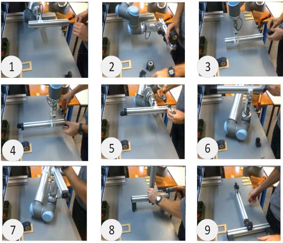
Fig. 7. Collaborative assembly with the robotic arm [2].
Moreover, for ergonomic purposes, the position of the element being assembled and carried by the robotic arm should change according to the operator’s size.
Robotic grasping. Grasping is a fundamental task throughout robotics, as it enables further manipulation and interaction with the robot’s environment. In many of today’s and future applications like pick-and-place tasks in manufacturing, large-scale warehouse automation or service robotics, reliable grasping of unknown objects remains challenging. In particular, bin picking is the task of grasping objects out of unsystematic environments like a randomly filled bin. Several difficulties in comparison to general robotic grasping are highlighted: Noisy sensor data, an obstacle-rich environment, and a usually contact-rich task execution.
State-of-the-art industrial solutions require an object model, which is localized within a point cloud via pose estimation. Usually, it is then grasped at pre-defined points.
Figure 8 demonstrated industrial robotic manipulators [3-5] with grasped at pre-defined points.
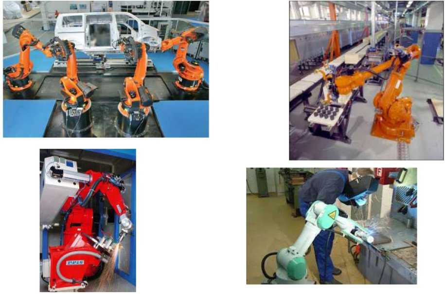
Fig. 8. Examples of industrial robotic manipulators with grasped at pre-defined points [7]
However, model-free solutions for unknown objects continue to pose a challenge.
Figure 9 demonstrated industrial robotic manipulators with grasped at for unknown objects continue to pose points.
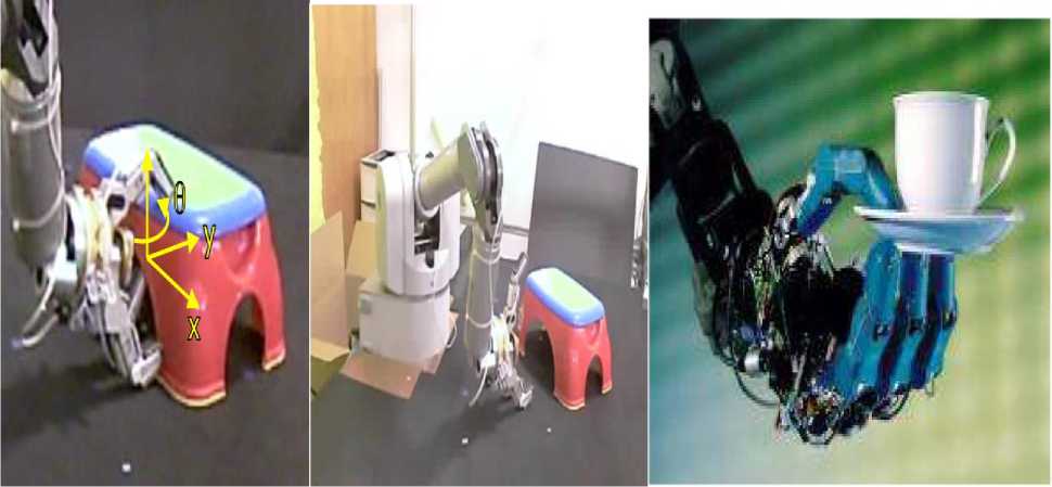
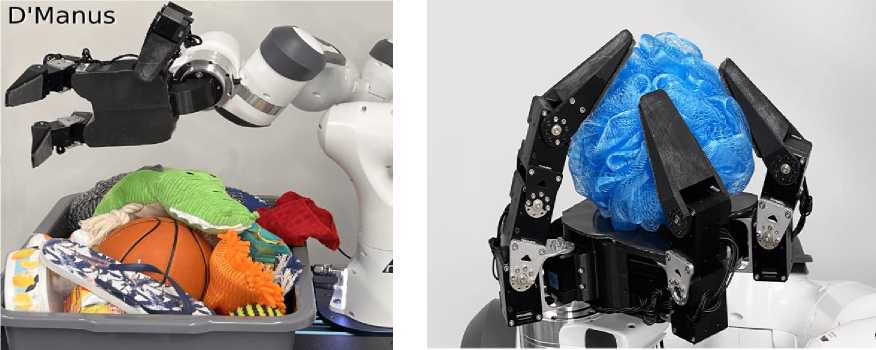
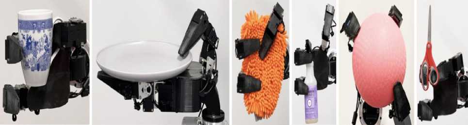
Fig. 9. Examples of industrial robotic manipulators with grasped at for unknown objects continue to pose points
[The D’Manus – a low-cost, 10 DoF, reliable prehensile hand with all-over ReSkin sensing. Data collection setup: Tactile data is collected by placing the object on the palm and executing a human-scripted interaction policy for motor babble . Illustration of the D’Manus grasping different objects [8].]
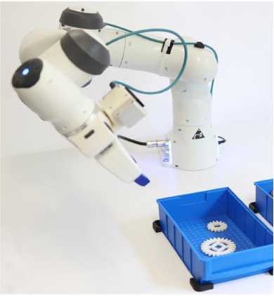
Robot learning . Robot learning has great potential for manipulation tasks. As data-driven methods have the intrinsic capability to generalize, a universal grasping controller for many objects and scenarios might be within reach. As the data consumption remains the practical bottleneck for learning methods, the action space is frequently simplified to reduce costly exploration. Oftentimes, planar manipulation with 4 DoFs is used (see Fig. 10).
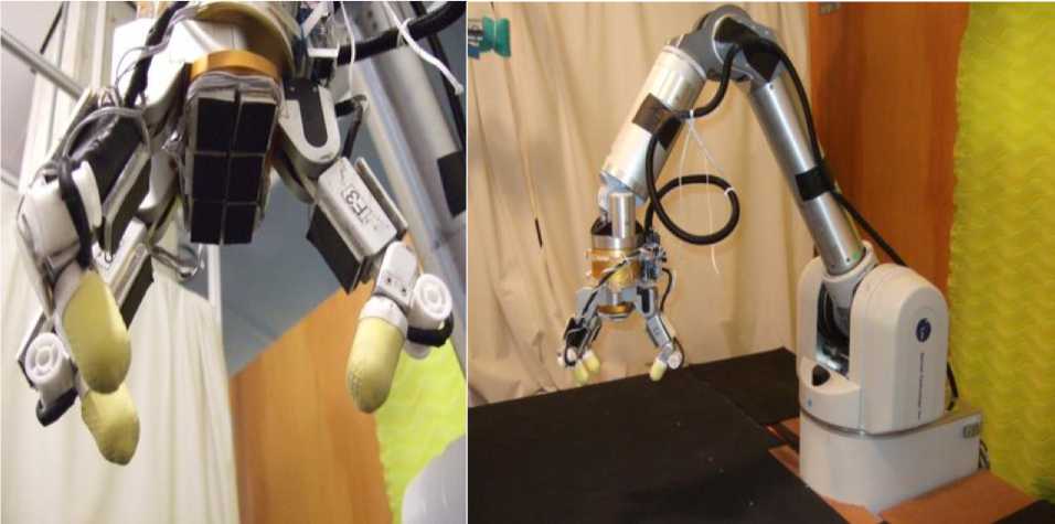
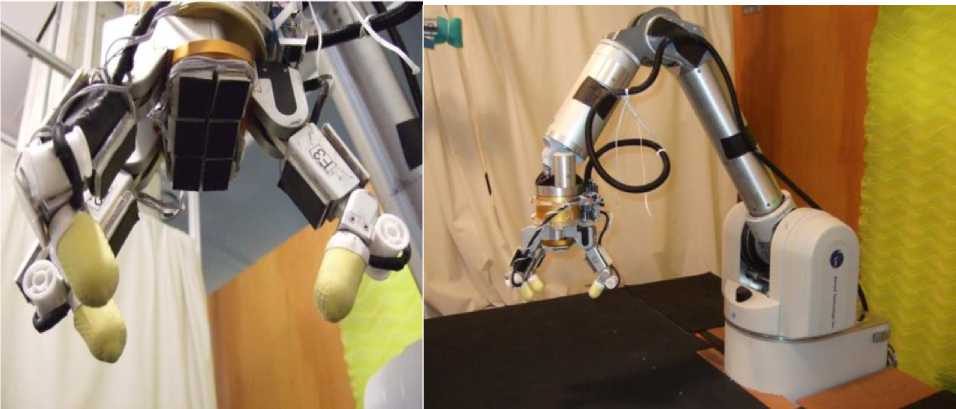
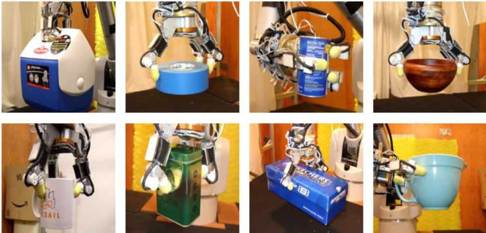
Fig. 10. Examples of robotic manipulators grippers
In general, this is a powerful yet efficient simplification regarding bin picking, in particular when combined with a fully-convolutional neural network (FCNN) for calculating grasp quality scores. Still, planar grasping leads to a restriction of possible poses, in particular regarding collisions between the gripper and the bin. For real-world training, a Franka Panda robot, the default gripper, and custom-made jaws (Fig. 11) were used. A Framos D435e RGBD-camera is mounted in the eye-in-hand configuration. Performance was measured on a system using an Intel Core i7-8700K processor and a NVIDIA GTX 1070 Ti. In front of the robot, two bins with a variety of objects for interaction are placed.
Robot learning in grasping . Robot learning has shown great progress in recent years. Due to its ability to generalize, many approaches can easily be applied to unknown objects. For the task of grasping, it was find that two major approaches have emerged: First, an end-to-end approach using a velocity-like control of the end-effector. Although this is a very powerful and expressive approach, it requires a lot of data due its time-dependent, high-dimensional action space. Second, a single-step approach using manipulation primitives.
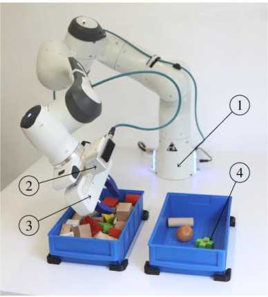
Fig. 11. The robot avoids a possible collision with the bin by adapting the two lateral degrees of freedom by a model-based controller [9]
[The remaining planar grasping is learned in a self-supervised manner from real-world experiments. We evaluate our hybrid approach using the task of bin picking. The system includes a robotic arm (1), a RGBD stereo camera (2), a two-finger gripper (3), and two bins with a multitude of objects (4).]
Despite viewing from a lateral orientation ( u 0:5 rad), the robot is able to grasp flat objects planar to the table. A controller decides where to apply which pre-defined primitive. Combined with a fully-convolutional neural network (FCNN) as an action-value estimator, this approach has been applied to a wide range of tasks including grasping, pre-grasping manipulation or pick-and-place.
Domestic service robots have been developed considerably in recent years, while the creation of a robot chef in the semi-structured kitchen environment remains a grand challenge. Food preparing and cooking are two important activities that take place in the household, and a robot chef who can follow arbitrary recipes and cook automatically would not only be practical but also bring new interactive entertainment experience. Several works propose to use a bimanual robot to realize food preparing processes, such as peeling motion or serving traditional Swiss raclette. Recently, a project called RoDyMan aims at a non-prehensile dynamic manipulation of deformable objects, mainly focusing on pizza making via a bimanual robot.
We are concerned about solving the problem of human-like robot cooking with the stir-fry movement, which is a significant and complicated bimanual skill in Chinese cooking art.
It requires the dual arms of the chef or robot to bring a wok and a spatula, respectively [9], as shown in Fig. 12. And it aims to realize a desired visual and cooking effect by rolling and tossing the content objects through the coordination of this two cookware.
Achieving stir-fry with a robot is an intractable task, since many related control problems are still not fully developed. First, stir-fry is a non-prehensile manipulation where the state of the operated content is subject only to unilateral constraints and the dynamics of both the food content and the end-effector, as well as the related kinematics [4]. Second, the content in the wok are various in size, weight and stickiness. Due to the difficulty of modeling, the manipulation consequences are hard to obtain. Thus, it is difficult to design a general control method. Third, since dual arms interact indirectly via cookware, the modeling of the robot system is heavy manual work and inconvenient to migrate to other cookware.
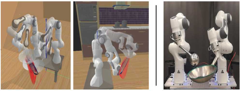
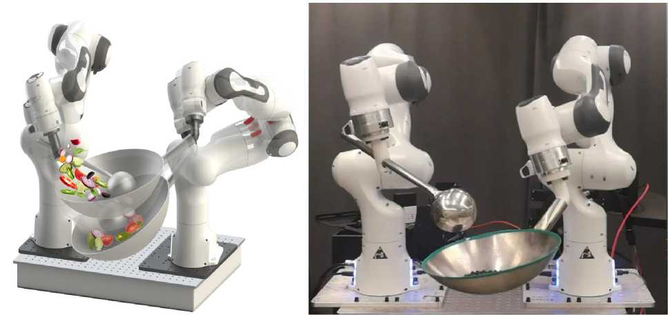
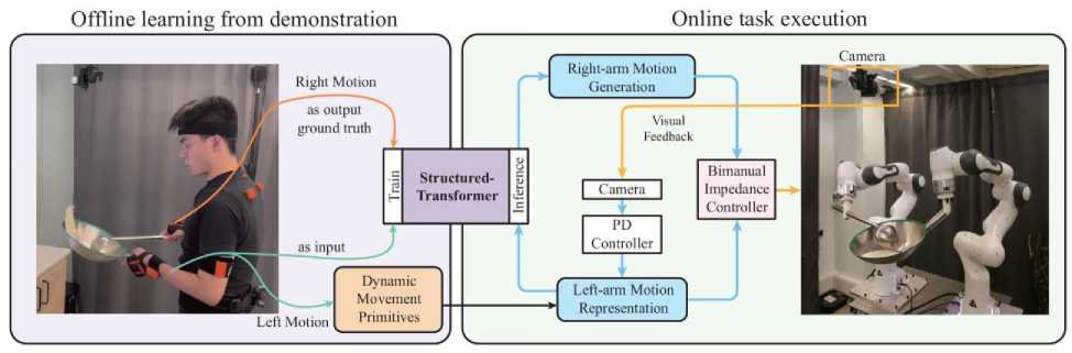
Fig. 12. The dual arms of the chef or robot to bring a wok and a spatula (up and middle); The proposed decoupled coordination framework comprises two parts: off-line learning from demonstration and online task execution (down) [10]
Finally, the movement of stir-fry is highly dynamic and requires continuous bimanual coordination throughout the task. In the off-line process, dual arms are decoupled into different roles and treated by a classical method and a neural network method separately. Here adopted a DMP and propose a spatiotemporal neural network - Structured-Transformer for learning the coordination. In the on-line process, leftarm motion is adjusted according to the visual feedback and the corresponding right-arm motion is generated by the pre-trained Structured-Transformer model based on the left-arm motion.
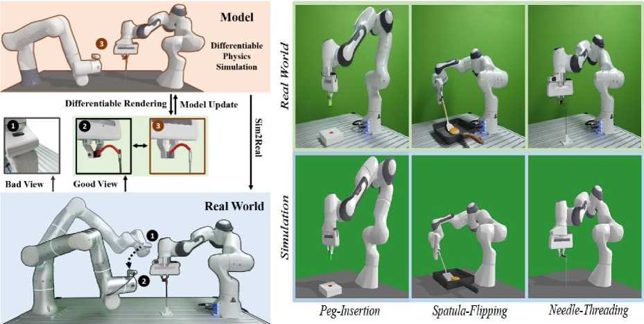
How an accurate model can be developed automatically and efficiently from raw sensory inputs (such as images), especially for complex environments and tasks, is a challenging problem that hinders the broad application of Model-based reinforcement learning (MBRL). It was proposed a sensing-aware model-based reinforcement learning system called SAM-RL. Leveraging the differentiable physics-based simulation and rendering, SAM-RL automatically updates the model by comparing rendered images with real raw images and produces the policy efficiently. With the sensing aware learning pipeline, SAM-RL allows a robot to select an informative viewpoint to monitor the task process (Fig. 13a).
(a)
(b)
Fig. 13. (a) The proposed [11] SAM-RL enables robots to autonomously select an informative camera viewpoint to better monitor the manipulation task (for example, the needle threading task); Visualization of experiment setup for Peg-Insertion, Spatula-Flipping, and Needle-Threading (b)
The differentiable leverage rendering to update the model by comparing the raw observation between simulation and the real world, and differentiable physics simulation to produce policy efficiently. Three different manipulation tasks as shown in Fig. 13b: inserting a peg into a hole (Peg-Insertion), flipping a pancake with a spatula (Spatula-Flipping), and threading a needle (Needle-Threading). The Peg-Insertion task is considered successful if the peg is inserted into the hole. The Spatula-Flipping is successful if the pancake is lifted up by the spatula and then flipped. The Needle-Threading is successful if the thread is put through the needle’s hole.
Extensive experiments in the simulation and the real world demonstrate the effectiveness of proposed learning framework.
Surgical robotics research . In recent years, teleoperated robotic platforms have gained the scientific community’s attention thanks to the emergence of new applications in several fields, especially in surgical robotics, where surgeons exploit the robot’s dexterity to perform challenging medical procedure. Aiming for greater robot autonomy, several platforms have been developed for surgical robotics research, for instance the dVRK and the RAVEN. The former is based on the first-generation da Vinci robot hardware and the latter are based on custom open hardware. Both systems are based on cable-driven mechanisms, and, different from serial manipulators, they often require additional strategies to compensate for the inaccuracies related to slack and stretch of the cables. Because of that, several platforms based on industrial serial manipulators have been proposed [4,12,13]. An open platform for surgical robotics (MOPS) research based on serial manipulators, has high modularity, uses commercially available robot arms, and allows scalability with custom tools. In addition to all these features the platform includes a novel hardware design, which is oriented to dexterous cooperative task manipulations, and targets general experiments for scientific exploration.
The proposed [12] robotic system is shown in Fig. 14.
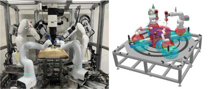
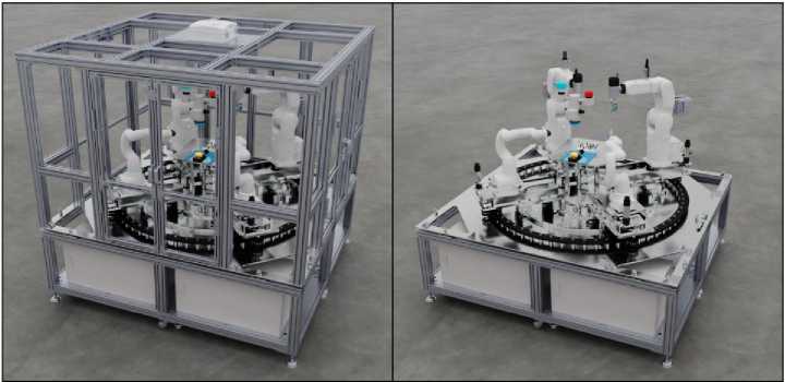
Fig. 14. A picture of the first prototype of AI science platform
[The four robotic arms can be individually controlled.]
Geometric primitives on CoppeliaSim defined, as shown in Fig. 14. [Snapshot of the CoppeliaSim scene. The blue and red spheres are geometric primitives defined by the user.] The kinematic controllers use these primitives to impose VFIs that prevent (self)-collisions. These primitives, in addition to a configuration file, are used by the kinematic controllers to define safe distances between the primitives, and consequently, prevent (self)-collisions by means of the VFIs framework. This task is done automatically each time the kinematic controllers’ nodes are started. Isaac Sim allows different development workflows such as UI, Python API, and ROS. The Python API standalone workflow since enables more features than the others and avoids the ROS dependency.
Figure 14 (down) shows the render of the scene using the path tracing algorithm. [Path tracing render on Isaac Sim. On the left, the safety cage of the platform is displayed. On the right, the cage was removed for the sake of the visibility of the inner components.]
The preparation of the mouse for the experiments was done manually by removing the skin on top of the cranium and fixing the mouse under camera vision. One operator was tasked with handling the microdrill and the cotton swab. When the mouse is alive, the cotton swab and other tools are used to control and stop bleeding. In our case, the cotton swab was used to keep the cranium wet using tap water inside a small plastic container. The user operated the robot to wet the cotton swab and then applied it to the cranial surface.
After that, the user performed the drilling of the skull. Those steps were repeated for about 5 minutes. After that, the second user, seated in another computer and having access to their own master interface, operated the tweezers. The operator could successfully remove the cranial patch. Snapshots of this procedure are shown in Fig. 15.
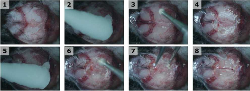
Fig. 15. The world’s first reported teleoperated cranial window in an euthanized mouse [12]
[Two users and three tools were used. The first user handled the microdrill and the cotton swab. The second user handled the tweezers that were used to remove the circular cranium patch. The only feedback available to the users are the camera images and the sound. This was a feasibility experiment in which time was of no particular essence; but, nonetheless, we were able to make a proper circular hole within 6 minutes.]
These initial results show the dexterity and usability of such a complex system in many different settings. There is ongoing work in using this platform for AI research toward scientific exploration (Fig. 16).
(a)
(b)
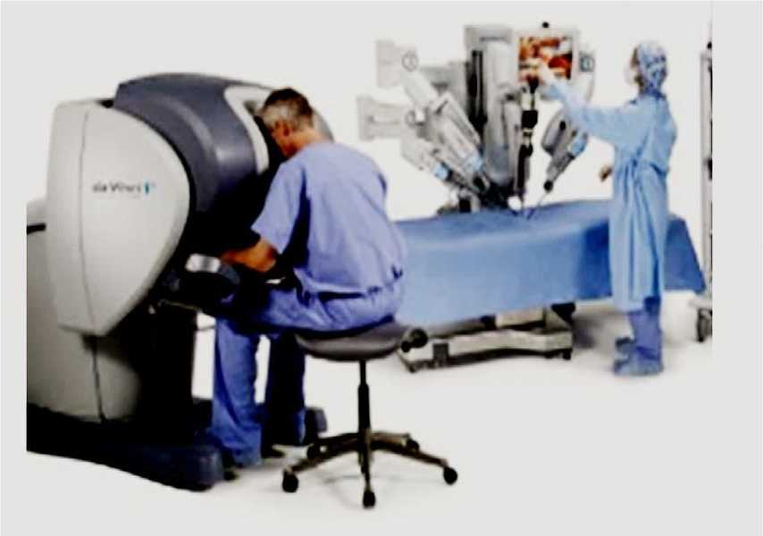
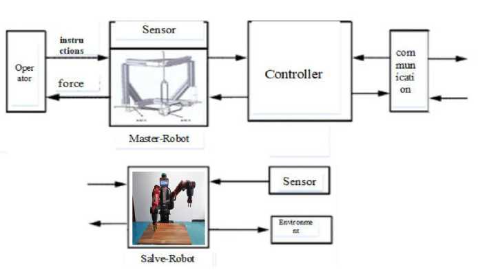
Fig. 16. Remote intelligent control on the first-generation da Vinci Research Kit (a); Asymmetric Teleoperation System (b) [13]
The type of master–slave teleoperation system can be divided into isomorphism and asymmetric. For the Rokviss teleoperation robot, which was developed in Germany, its main application task is to complete the international space station and perform some ground experiments. The Da Vinci surgical robot system is shown in Fig. 16; doctors can use the “Da Vinci” surgical robot system to perform minimally invasive surgery on patients. Telesurgical robotic systems provide a well-established form of assistance in the operating theater, with evidence of growing uptake in recent years. A new 6 DoF haptic device and an asymmetric teleoperation system are presented (as shown in Fig. 16), aiming at the tracking and transparency of the asymmetric teleoperation system; for single-joint PID control, the simulation experiment results showed that the performance of tracking is poor. A robust control algorithm based on the state feedback observer is proposed and simulation experiments was carried out on the new control algorithm . Until now, the da Vinci surgical system (Intuitive Surgical Inc, Sunnyvale, California) has been the most widely adopted robot of this kind, with more than 6,700 systems in current clinical use worldwide. Robotic-Assisted Minimally Invasive Surgery (RMIS) has gained significant popularity in recent years due to its advantage of causing less tissue trauma and reducing hospitalization time for patients. Of all surgical robotic platforms available in the market, the da Vinci robot (Intuitive Surgical Inc, Sunnyvale, California) has dominated RMIS, with more than 10M operations having been performed on this platform in the past twenty years.
To further propel RMIS research on the da Vinci surgical platform, in 2014, an initiative was launched to repurpose retired first-generation da Vinci robots by converting them into da Vinci Research Kits (dVRKs) [14], which consist of both a software package and hardware controllers. These dVRKs have been distributed to research institutions around the world (Fig. 17).
For automatic surgical tasks, the accuracy of hand-eye calibration is of paramount importance because all robot motion commands are generated out of visual information captured by the endoscopic camera, and these visual cues cannot be correctly perceived by the robot arm unless an accurate transformation matrix is provided.
Figure 17, shows an example of this artifact in a video of a real ex vivo surgery.
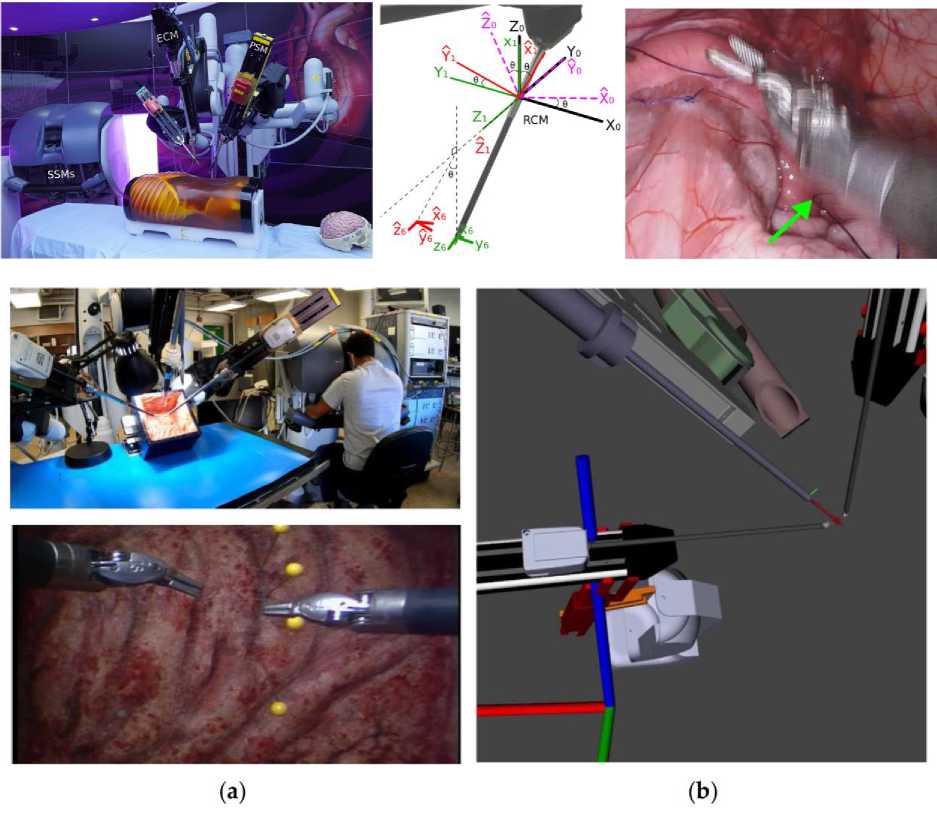
Fig. 17. The first-generation dVRK with two surgeon-side manipulators (SSMs), three patient-side manipulators (PSMs) and one endoscopic camera manipulator (ECM)
Four main challenges arise [15] when trying to implement a methodology to exploit cobots in the above-mentioned conditions; these are the starting points of this project:
-
• Expert engineers are needed for designing, programming and testing the robotic application.
-
• Programmers need to know the workstation requirements for developing the precise production process.
-
• The robot adoption in such production process conditions has to be technically justified, since small and varied batches are involved.
-
• Investment costs are certainly significant, and the economic return has to be assured.
Robot programming is recently evolving from the traditional written language to new more accessible directions. For example, kinesthetic teaching applied to a walk by demonstration approach simplifies a lot the work load required for programming a machine, and its path towards industry is on track, being regulated by ISO/TS 15066.
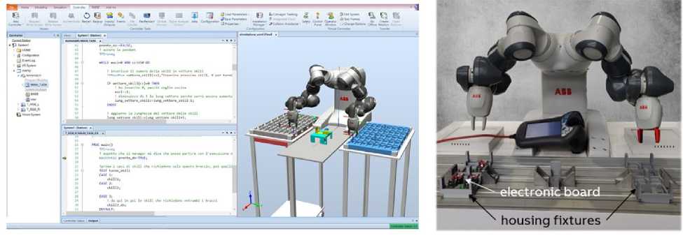
Figure 18 reports an example of the code through which the program manager code was developed (Fig. 18a), and a frame of the developed robotic procedure, in which it is visible that the two arms can operate at the same time (Fig. 18b).
(a)
(b)
Fig. 18. Implemented Firmware up-date process for security sensor electronic boards. (a) Software development for manager program. (b) View of the two Yumi arms operating at the same time [13]
In the figure the fixture specifically designed to house the electronic boards is visible, for each of the two arms.
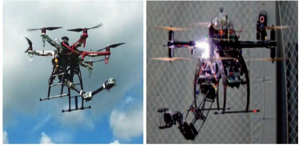
Building transport robotic arms and legged industrial manipulators . Examples of 6 DoF building transport robotic arms and industrial manipulators on Fig. 19 demonstrated.
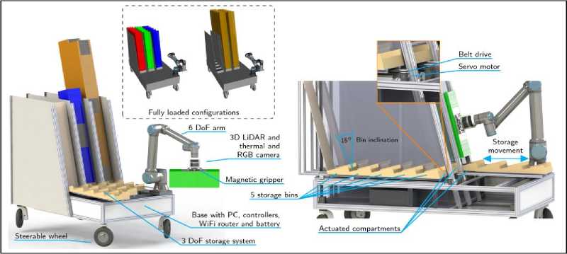
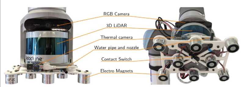
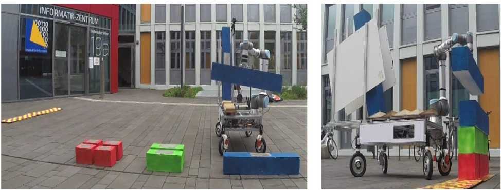
Fig. 19. Examples of industrial 6 DoF transport manipulators applications [4,5]
Almost all humans are familiar with the ability to throw objects, as we learn how to throw a ball during a game (e.g., basketball) or an object into a bin (e.g., tossing dirty clothes into the laundry basket). It throws objects either to speed up tasks by reducing the time of pick-and-place or to place them in an unreachable place. Therefore, adding such a throwing motion to a robotic manipulator would enhance its functionality too. In particular, throwing object is a great way to use dynamics and increase the power of a robot by enabling it to quickly place objects into the target locations outside of the robot’s kinematic range. However, the act of precisely throwing is actually far more complex than it appears and requires a lot of practice since it depends on many factors, ranging from pre-throw conditions (e.g. initial pose of the object inside the gripper) to the physical properties of the object (e.g. shape, size, softness, mass, material, etc.). Many of these elements are challenging to describe or measure analytically, hence, earlier research has frequently been limited to assuming pre-defined objects (e.g., ball) and initial conditions (e.g., manually placing objects in a per-defined location). To accomplish this task successfully, the robot should perceive the environment through its RGB-D camera, and then infer the proper parameters to throw the object into the basket
The experimental setups in simulation and real-robot are depicted in Fig. 20.
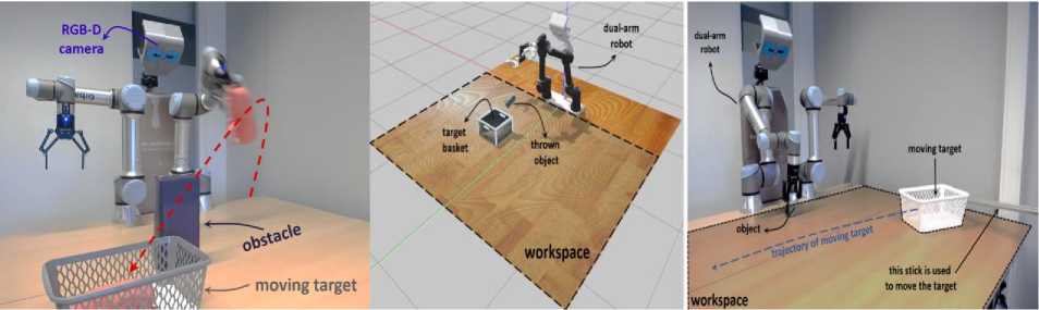
Fig. 20. An example scenario of throwing an object into a moving basket located outside of the robot’s workspace while an obstacle obstructing the path [16]
In particular, it is developed a simulation environment in Gazebo utilizing an ODE physics engine, which is very similar to our real-robot setup. The setup consists of an Asus - camera, two Universal Robots (UR5e) equipped with two-fingered Robotiq 2F-140 gripper, and a user interface to start and stop the experiments. It was trained a policy to modulate throwing kernel parameters through RL to enable robots to precisely throw objects into a moving basket while there are obstacles obstructing the path. In particular, our method learns to handle a wide range of situations and avoid colliding the thrown object with the obstacle. With this formulation, the robot could iteratively learn the aspects of dynamics that are difficult to model analytically.
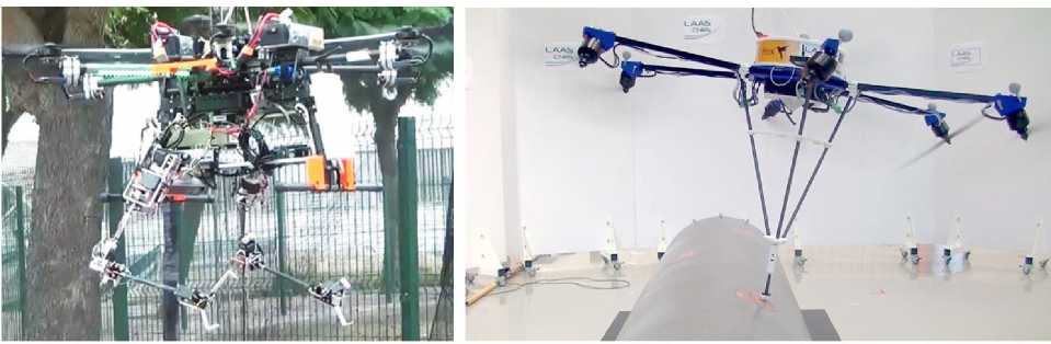
In recent years, legged (quadruped) robots have been subject of technological study and continuous development. These robots have a leading role in applications that require high mobility skills in complex terrain, as is the case of Search and Rescue (SAR). These robots stand out for their ability to adapt to different terrains, overcome obstacles and move with in unstructured environments. Most of the implementations recently developed are focused on data collecting with sensors, such as lidar or cameras. The Robotics platform used for this development is a quadruped of the Unitree A1 model ARTU-R (A1 Rescue Task UPM Robot), equipped with a sensory system and a robotic arm. Both the Hololens 1st and 2nd generation glasses have been used for tele-operation with Mixed Reality (Fig. 21).
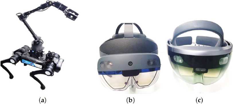
Fig. 21. Materials used to validate the proof of concept. (a) Robotic set (ARTU-R + 6 DoF Robot Arm); (b) Hololens Microsoft 2nd Generation; (c) Hololens Microsoft 1st Generation [17]
The main contribution of this work is focused on the High-level control of the robotic set (Legged + Manipulator) using Mixed-Reality (MR). An optimization phase of the robotic set workspace has been previously developed in Matlab for the implementation, as well as a simulation phase to verify the dynamic functionality of the set-in reconstructed environments. The first and second generation of Hololens glasses have been used and contrasted with a conventional interface to develop the MR control part of the proposed method. Several tests have been performed to validate the operability of the robotic set through MR (Fig. 22), by using both models of Hololens and conventional interfaces to determine their advantages and limitations. The MR tele-operation system has been evaluated in terms of versatility, immersive experience and user confidence to control of the robotic set. The third phase of tests has been developed in reconstructed environments (indoors and outdoors), consisting of victims (mannequins and people) and small debris (Fig. 22).
In this test, the task consists in take a first-aid kit from point A to point B (victim). In the first instance, robot approaches and takes the payload (Fig. 22a–c), places the arm in the transport position and moves through the environment until reaching the victim (Fig. 22d). Finally, robot extends his arm and drops the package near the victim (Fig. 22e). The entire process is tele-operated by the robot from the remote control and the arm from the MR system.
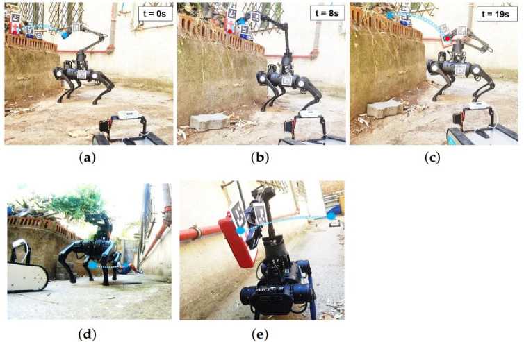
Fig. 22. Test for manipulation payload in outdoors (a–c) using the MR system. Indoors: Test for robotic assistance transporting medical equipment to a victim (d,e). (a) First pose for payload manipulation. (b) Robot set grabbing payload. (c) Transport pose of the payload. (d) Robot transporting the payload to the victim. (e) Robot arriving the destination [17]
The main advantage of the proposed system is the versatility it offers the user, making possible the gestural control of a complex robotic system and providing a more direct interaction of the environment, the robot and the workspace. The portability of the system should also be highlighted since it depends only on the glasses, a laptop as a central communications system, and the robot, which is a great advantage over other proposed methods that use large equipment and, above all, high costs.
Intelligent robotic assembly line . Industrial AI applications utilize their forecasting capability for business intelligence, such as supply chain demand planning, and supplier assessment and selection. Computer-integrated and generative product design are other well-received AI applications in the manufacturing industry. Beyond state-of-art AI algorithms, industrial AI applications require reusable system integration, faster solution identification, and more efficient integrations. These industrial use cases have led to the “5S” requirements for industrial smart systems: systematic, standards, streamline, speed, sustainable [18]. Equipped with these requirements, AI-enabled smart manufacturing systems are often implemented with system-embedded closed-loop controls, with cognitive abilities to deliver manufacturing intelligence driven by data and knowledge from devices, processes and, even more importantly, product designs. On a macro scale, future manufacturing industry have been envisioned to address the competition over information technologies provided by intelligent, autonomous, and interoperable industrial systems. It has been concluded that context awareness, interoperability, and compositionality are commonly used to classify a system as a smart manufacturing system.
System integration of manufacturing intelligence has therefore been an enabling technology to prepare factories and enterprises for the next evidence-based control and management era, where competitions between enterprises are placed in information technologies. The gaps that need to be filled beyond current experience-based control or management solutions are the system’s capabilities to interpret: (1) process factors not directly available from signals such as images, heatmaps, etc.; (2) the hidden relationships between process factors; (3) the relationship between process factors and quality of process. Moreover, reusability and reconfigurability further indicate the readiness of an AI approach in smart manufacturing systems, namely, the convenience and the compatibility of solving problems on similar devices using the same problem-solving process.
The future of manufacturing is reinventing itself by embracing the opportunities offered by digital transformation, industrial internet, cognitive automation, and AI. Cyber-physical systems (CPSs) are looking to pursue the potential convergence of cyber architectures, physical manufacturing processes, and control intelligence. A novel cyber-physical infrastructure enabled by these technological elements introduced, followed by proposing to utilize a machine vision system to aid general manufacturing event understandings.
The design of vision system for process and health monitoring in a robot assembly line is introduced in [18]. The proposed visual system is composed of high-resolution security cameras, wireless on-robot inspection cameras, material tracking drones and infrared thermal cameras (Fig. 23).
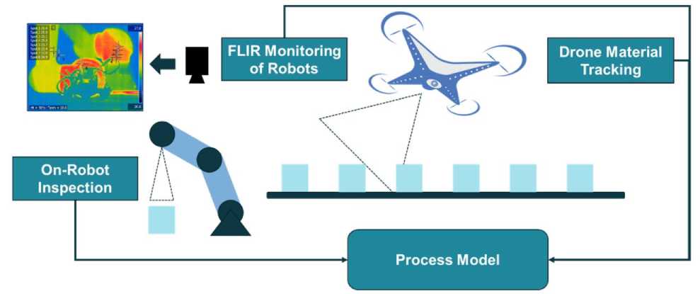
Fig. 23. Vision-aided process/health monitoring system for proposed robotic assembly line
Depending on the data source and use cases, collected data are either transferred to a cloud server or analyzed at the edge. The cyber infrastructure will receive, process, and distribute the inference results from the cloud or the edge for a synchronized semantic integration in the control loops. Semantic integration of the vision system provides interoperable signals in an organized manner while ensuring all vital information is readily available for a human user or a machine end.
Precise understanding of a manufacturing scene requires analyzing feeds from multiple cameras (security cameras, inspection cameras, drones, thermal cameras, etc.) as well as learning the “manufacturing context” as defined by the other sensor data, participating objects, and sub-processes. Acquiring this knowledge in a generalized and transferable form aids in properly understanding the underlying manufacturing event.
A computationally feasible intelligent system embedding by distributing computing powers has been commonly approached by two stages: (1) signal processing and expert feature extraction at the edge or near the source of data, and (2) data-driven modeling and cumulative learning on the server (local or cloud). Semantic integration methods of this proposed vision system are discussed in this section with two implementations: (1) cloud-based service-oriented object recognition; (2) customizable local shape recognition. A novel method of image dataset augmentation is also proposed by the aid of the constructed digital twin setup.
The control architecture (Fig. 24) consists of 4 major components: physical cell, DT, cloud service, and the edge-end computing engine. These components are assigned with different tasks.
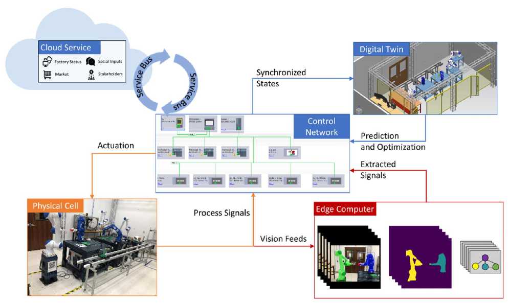
Fig. 24. Proposed CPS-enabled control for future factories
[Control network administrates physical cell and digital twin to synchronize process signals and intelligently actuate field devices by system smart layers. System smart layers consist of business intelligence from cloud services and semantic integration of visual signals from the edge ends.]
Data collected from the (1) physical cell are transmitted to: (2) the cloud-end for business related big data analytics; (3) the digital twin for fast simulation-based status prediction and fast optimization; (4) edge computing for fast device status extraction. All of these data transmission must be reported and administrated by control network hosted by OPC-UA server in PLC devices. Derived optimal action can be pushed to either the digital twin for virtual commissioning or the physical cell for deployment.
In fact, this high-fidelity simulation-based DT [12] adds another layer of expert knowledge and substantially increases the reliability of data-driven approaches adopted in the control loop.
Transfer learning (TL) is another important approach in the machine learning field. TL intends to leverage prior trained models to resolve more specific, unexplored, and more complicated datasets instead of training models from scratch. TL is highly facilitated by reusing pretrained neural networks as they successfully learned useful features in encountered datasets. Normally, training large networks such as ResNets from scratch requires enormous datasets for convergent results. This is caused by a large number of parameters for wide-ranging image recognition tasks, e.g., ResNet-50 has over 23 million trainable parameters. Pretrained Mask R-CNN weights on a Common Objects in Context (COCO) dataset is set as the starting point to train the dataset. Although pretrained model can recognize 80 classes of COCO object types, including human, plane, table, etc., we still need to define additional classes to understand a robot assembly process.
In a robotic manufacturing scene (Fig. 25), pre-trained Mask RCNN model on COCO is already able to correctly detect defined objects such as the tables, cups, screens, bottles, and chairs.
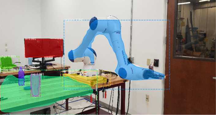
Fig. 25. Detecting robotic manufacturing scene using pretrained Mask R-CNN model on COCO dataset as the starting point
However, manufacturing assets that are not pre-defined by COCO dataset need to be defined based on the application. In this scene, the shapes of robot fixture and robot arm are successfully detected with incorrectly recognized object classes. Thus, the work based on this pretrained model needs to define indicative manufacturing object classes for event understanding tasks, including the robots, alignments, parts, and fixtures. Any other types of Feature-of-Interest can be further defined should they make contributions to process understanding, such as manufacture features of parts, robot joints, gripper fingers, or the conveying systems, etc. Higher resolution of object class definition will facilitate the understanding of process, meanwhile requires increased samples to adequately train the existing model, especially for uncommon object classes such as customized parts and grippers.
-
I.2. Novel aerial platforms
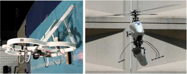
Most of the studies presented in the literature are using commercial UAVs for the aerial manipulation research. However, researchers have also proposed, novel platforms, modification to existing platforms, whereas [19] presented a technique of designing a new aerial platform based on application. Various new trends are being observed, one of them is exploring the possibility of hybrid aerial vehicles which can move on various mediums such as water and ground along with flight capabilities [20], and the other trend is creating re-configurable vertical take-off and landing aircrafts (VTOLs), which do not have fixed shapes. An account of all these is discussed below.
Aerial manipulators. The modification was proposed by [21] in the form of the addition of a buoyant structure to the quad-rotor to overcome the instability of the flight for redundant manipulators as shown in Fig. 26a.
Researchers planned to attached a manipulator to the proposed hybrid UAV. The test show that this hybrid structure without the manipulator does stabilize the flight. However, having attached a buoyant structure such as the one shown in Fig. 26a must add the aerodynamic effects such as parasitic drag. It also increases the lateral surface area which means that perturbations caused by wind might offset the benefit that is being achieved by the addition of buoyant structure.
Another novel aerial platform recently presented, is called, spherically-connected-multi-quadrotor platform (SmQ Platform) as shown in Fig. 26b. Three quadrotors were attached to small beams using spherical joints. The small beams were concentrically connected to a small circular plate acting as the base frame. The connection of multiple quadrotors to a single frame allows increasing the total thrust force that can be generated by the aerial platform. SmQ platform is also able to execute yaw motion and can apply horizontal force using a link that is extending out from the base frame. The system although is over-actuated, but the actuation is limited by the range limit of spherical joints. Another novel aerial platform recently presented, is called, omni-directional-aerial-Robot (ODAR) as shown in Fig. 26c. ODAR is a fully actuated aerial platform with reversible ESCs which can produce a bidirectional current; hence the ODAR platform can apply force in both directions; a feature that is currently not available in conventional commercial multi-rotors and helicopters.
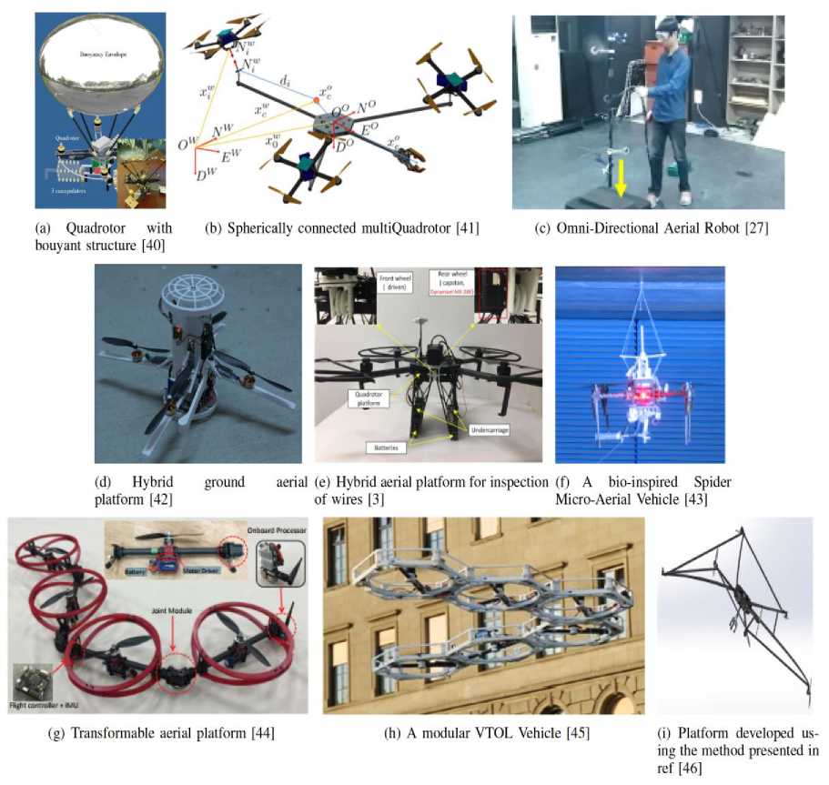
Fig. 26. Examples of novel aerial platforms
Researchers have also tried to create a hybrid platform, which can not only fly but travel through another medium. One example is shown in Fig. 26d in which the aircraft can not only fly and hover in the air but also travel on the ground, after going through a transformation, where it folds its arms and forms a two -wheel vehicle. This kind of hybridization, can increase the reach of aerial platform further and also save energy by traveling through the ground when flying is not necessary. Another example is where the aerial platform can not only hover and travel underwater, but it is also capable of flying in the air, during the same flight. In above two cases, the prospects of attaching a manipulator are yet to be explored, and integration of a manipulator to such platforms would require considerations, regarding the travel through another medium based on the requirements of the other medium. Another example of an aerial platform traveling through another medium is shown in Fig. 26e, where the drone can hover in the air, but it can also land on wires for inspection, and after landing it can travel on wire, and fly again, in case of any obstacle on the wire. Another example is the Fig. 26f, which has an additional mechanism to launch anchors. These anchors attach to the surroundings and hence provide support to the UAV. This anchoring or perching allows the UAV to save energy instead of the usual hovering in position performed during an aerial manipulation operation.
A novel concept is the use of a transformable aerial platform, where the whole platform can act as a gripper. In this case, the aerial platform consists of rotor arms, which can change their configuration, as compared to fixed rotor arm multi-rotors as shown in Fig. 26g. In this type of arrangement, any external manipulator arm or gripper is not required. In a demonstration, it successfully transformed itself such that it encompassed the box, grasped it and lifted it. The transformation of the aircraft also makes it more successful in navigation through narrow passages as compared to other types of multi-rotors, since it can transform its shape based on the passage. Since the whole platform transforms and interacts with the object, it seems necessary to add a protective ring around the rotors to protect the rotors and the object. This is not necessary for conventional multi-rotor manipulator systems since a manipulator adds reachability and provides some disconnection from the instabilities of interaction with the object.
A similar concept is having a modular vertical and take off vehicle, as shown in Fig. 26h where, multiple individual modules with single rotors, can join together via magnets to form various configurations. The individual modules use wheels to move around on the ground and connect to the other modules, and after forming a configuration, the modular VTOL can fly.
Another approach could be designing a platform from scratch, based on the application. Designing a new platform, instead of using existing ones, could provide more flexibility in terms of application-specific attributes that might not be present in existing quadrotors, hex-rotors or helicopters. These attributes could be a desired force or torque acting on the end-effector based on any application. Hence a technical analysis can be performed to determine the mechanical structure of the system, the number of thrusts and geometry. A platform is shown in Fig. 26i. It can be seen in the Fig. 26i, that the platform is quite unconventional in terms of its structure and the location of actuators on the platform.
A manipulator is defined as a control object added to the multirotor to extend its reach or reduce disturbances to the airborne platform during interaction with the environment. Attachment of a manipulator to a multi-rotor changes the dynamic behavior of the multi-rotor due to, change of center of gravity (CoG), the variation of inertia, and effects of dynamic reaction forces and torques generated by the movement of the arm. One way to tackle this change of dynamic behavior is by designing appropriate control algorithms that can reduce flight instability, and the other way is to design manipulators that reduce these three causes of instability. Control methods to deal with these causes of instability are discussed in the control section of Chapter 2, while this section is focused on the design of manipulators.
The design of manipulators attached to UAVs is strongly constrained by the weight of the arm, in fact, one of the most important design criteria is to improve payload to manipulator weight ratio. The weight of the manipulators can be reduced by the 1) selection of low weight material for manipulators; 2) selecting low weight actuators. The designs of the aerial manipulators are influenced by the requirements of certain desired characteristics. These desired characteristics of the manipulators may include, ability to absorb the impacts, reachability, dexterity, and compliance. Certain types of manipulators exhibit different characteristics, which is why it is essential to discuss the types of aerial manipulators.
As shown in Fig. 27a belts were used for the motion transmission for the third joint. Keeping the motors close to the base constrains the center of gravity of the arm as close as possible to vehicle base, thus reducing the total inertia and static unbalancing of the system. The manipulator was able to fold on itself during landing, or when not in use.
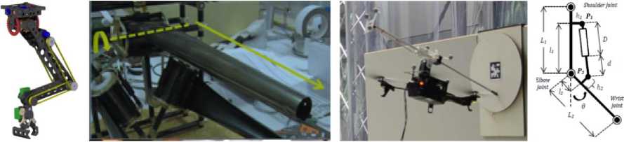
(b) A deployable manipulator [29]
(a) Arm with motors close to base, and motion transmission with belts [15]
(c) Arm with interlocking mechanism for im- (d) Arm with linear pact absorption [73] servo and spring for compliance [74]
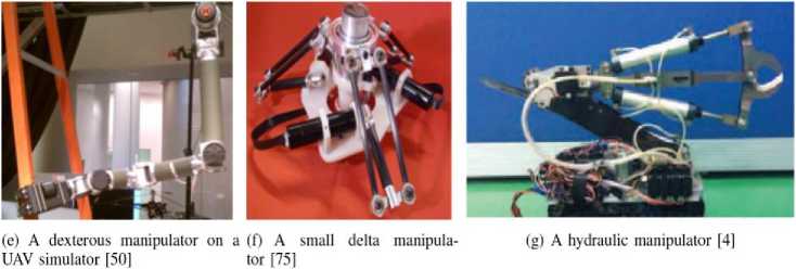
Fig. 27. Examples of manipulators, including serial, parallel link mechanisms and a hydraulic manipulator
A deployable, low mass manipulator for UAV helicopter shown in Fig. 27b, it was developed based on steel tubular booms which can be wrapped around a pulley and deployed when needed.
In general, both serial and parallel linked manipulators are susceptible to unwanted force or impact that could result in the transfer of this force to the base of the UAV and hence cause instability. However, in this section, some examples of serial link manipulators are presented where researchers have attempted to reduce these effects. Any unwanted interaction is usually dealt with by incorporating passive mechanical compliance. Springs or elastic bands are used to achieve compliant behavior. As shown in Fig. 27c, it proposed the design of an aerial manipulator, which includes a passive joint capable of storing impact energy in the form of elastic potential energy. The impact compresses the elastic band, while decompression is prevented by using mechanical interlocking. The resulting manipulator can absorb the impacts without making the UAV-manipulator system bouncing away from the impact object.
Another example of elastic joints is in which the joint was driven by a linear servo as shown in Fig. 27d. The linear servo and the link were connected via springs. These springs not only provided compliance but the elongation of springs also helps in determining the mass of the payload. Above methods of adding compliant behavior in manipulators are useful, but the compliant behavior, cannot be altered since it depends on the elasticity of the springs or elastic elements used.
Another study presented a design of a 7 degree of freedom arm (DoF) with 4 DoF of the hand as shown in Fig. 27e. Although the arm was attached to a test rig capable of mimicking an aerial platform, the authors claim that this manipulator can successfully manipulate and transport various objects while maintaining stable flight. One way to minimize the disturbances caused by the aerial manipulators is to use delta manipulators instead of a serial manipulator.
Delta configuration of manipulators is usually very light weight, and robust compared to a serial manipulator since the actuators are attached to the base. If the delta manipulator is attached to the UAV such that the force acting on the delta manipulator is passing through the CoG of the manipulator, it can counter some moments acting on the aerial platform due to the reactionary forces of the manipulator. Another example of delta manipulator is shown in Fig. 27f, where authors developed a non-destructive testing end-effector on a three degree of freedom delta robotic manipulator. The sensor is mounted on Cardan gimbal joint that allows the sensor to interact compliantly with the remote environment.
A low weight manipulator is favorable for aerial platforms, but in the case of a high torque requirement from an aerial manipulator, the criteria would be weight to power ratio. Applications such as cutting high tension cables require a very powerful end-effector which could provide very high power in a very short time. If electric motor actuators will be used higher torque can be achieved by the use of gears but that will also add additional weight and disturbance from the gearbox. A hydraulic manipulator as shown in Fig. 27g can be used to achieve such power. Although a hydraulic manipulator can be serial or parallel linked, it is classified differently here because of the actuation method and the promise of high torque.
A hydraulic manipulator was proposed to attain high force/torque ratio. A hydraulic manipulator is well suited for high payload capacity aerial systems since a hydraulic system is heavy. A decentralized control strategy requires some special considerations in terms of the stability of the whole system. A moving manipulator causes some instability in the flight of the UAV. This can be compensated by updating the inertia and CoG of the aerial manipulator system in real time.
As shown in Fig. 28, it is useful for the attitude controller to get a real-time update of the reactionary torque acting on the manipulator.
The reactionary torque can be obtained by placing a force sensor on the base of the arm manipulator, or it can be calculated by using the joint angles if the force sensor is attached to the end-effector.
Coming in almost all possible forms and sizes, the UAVs platform presented until now find their employment in a wide range of applications. In particular, as al-ready discussed, they have represented the means to fly a multitude of remote sensing instruments in several scenarios which have allowed to accomplish contact-less assignments. However, over the recent years, such platforms have demonstrated that it is possible to extend the spectrum of their potential applications. Thus, in-contact operations, where physical contacts with the environment are requested, can be performed. These demonstrations have led to extremely promising studies in the Aerial Physical Interaction (APhI) and aerial manipulation fields, which in turn have guided the community to conceive prototypes, functionalities and capabilities with the final aim of performing manipulation tasks while flying.
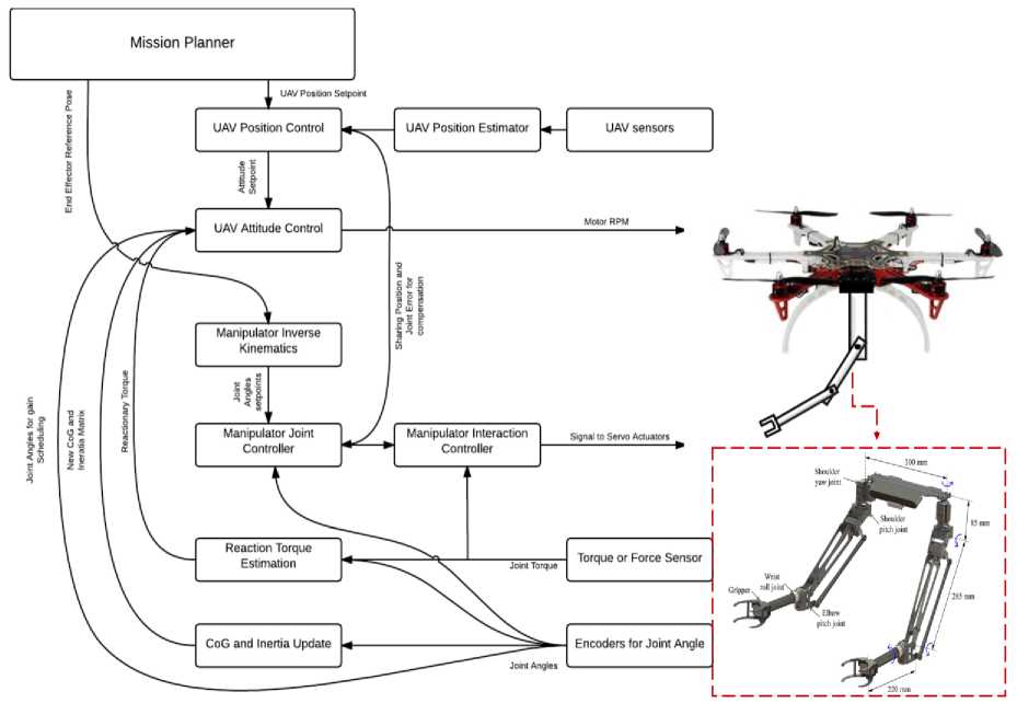
Fig. 28. A summary of different methods adopted in decoupled control scheme of UAV and manipulator
Such activities are characterized by active exchanges of forces and torques between the aerial vehicles and the environment. Therefore, the list of real-life employments of aerial robots can be extended appending tasks as, contact-based inspection and maintenance, assembly/construction and decommissioning of structures, transportation. The use of aerial robots in such unsafe or hazardous scenarios, provides, as a first result, the reduction of the risks for human operators and, from another point of view, the lowering of the costs related to such activities. An extensive and detailed survey on the topic that illustrates the assortment of the obtained achievements over the last 40 years can be found in [22,23].
Three predominant generations of aerial manipulators have ensued:
-
• Fist Generation: Conventional quadrotors with small enhanced capabilities ;
-
• Second generation: Aerial platforms adapted to interactions ;
-
• Third Generation: Advanced aerial platforms .
Examples of the first generation (see Fig. 29) are aerial platforms enriched with the ability to shove into walls, grasping objects, transporting objects with passive links, constructing structures.
(a) (b)
Fig. 29. First generation of aerial manipulators: (a) Flying robot interacting with a wall during a stable flight; (b) Aerial manipulation testbed carrying a tube
In such scenarios, their abilities of a major operational time and payload capacity have been significantly evident. Nevertheless, the same attention has been given both to helicopters and multi-rotor solutions. In particular, the advancements of the second generation provide relevant evidence of this statement (some examples are presented in Fig. 30).
(a)
(b)
Fig. 30. Second generation of aerial manipulators: (a) Flying Mobile Manipulator Unmanned Aerial Vehicle; (b) Aerial manipulator in an indoor environment
Rigid and compliant arms have started to be designed and placed on aerial platforms. Outdoor navigation sensors or the improvements of indoor navigation. With the promising advancements, the transition from conventional designs to less conventional ones have been moderately straightforward devices have off ered more reliable state estimation and thus more suitable flights for such platforms. Although the obtained achievements, the whole picture of aerial manipulators cannot be deprived of the third generation that represents, up to now, the category that contains the most advanced exemplars (see Fig. 31 for some examples).
(a)
(b)
Fig. 31. Second generation of aerial manipulators: (a) An aerial dual-arm manipulator with compliant joints; (b) A fully actuated platform interacting with the environment
This last family includes platforms reliable in both indoor/outdoor environments, fully actuated platforms, multiple arms, cable-suspended aerial manipulators, vehicles that leverage on on-board SLAM. Nevertheless, the development of autonomous or semi-autonomous manipulation systems still requires to solve open challenges. Payload capacity or wide-ranging workspace coverage are the most evident. Possible solutions have been found in combining the eff ort of several UAVs to cooperatively transport and/or manipulate objects.
Cooperative Transportation and Manipulation . Cooperative transportation and/or manipulation are primary abilities in groups of living beings. They represent powerful ways through which humans or animals interact with the environment and the external world in general. In the context of this thesis, the terms transportation and manipulation will be largely used. Although it may sound like they refer to the same action, we will highlight their diff erence with the aid of a simple example. With the term transportation, one or more entities are assumed to be able to move an object from one location to another, specifically from a point A to a point B. Hence, only three DoFs of the object are managed. Conversely, with the term manipulation , one or more entities are assumed to be capable of transporting and changing the orientation of the object at the same time and at any moment of the route. Therefore, the full-pose control can be obtained.
The distinction has been made to emphasize the major eff ectiveness of the manipulation. As a matter of fact, in most of the physical interaction tasks, the full pose control can represent either a strong requirement or an advanced feature. One may think of transporting objects that cannot enter in limited spaces unless tilting them, or peg-in-hole operations where the control of the position of the load is not enough. Cooperative manipulation skills involve a series of control decisions that mainly concern the definition of objects to interact with, the comprehension of the relative positioning, the determination of the sequence of actions to perform, the awareness of the uncertainties. Living beings perform such tasks requiring a dynamic perception, control and adjustment of their manipulation "tools", on the one hand, and sharp transitions between the body and the environment dynamics on the other hand.
With the aim of mimicking nature but also with the recent development of an increasingly technological world, significant eff orts have been made by scientists and engineers to investigate whether a swarm of robots could be envisioned with such skills. The relevant results that have been obtained will be discussed in the following (Fig. 32).
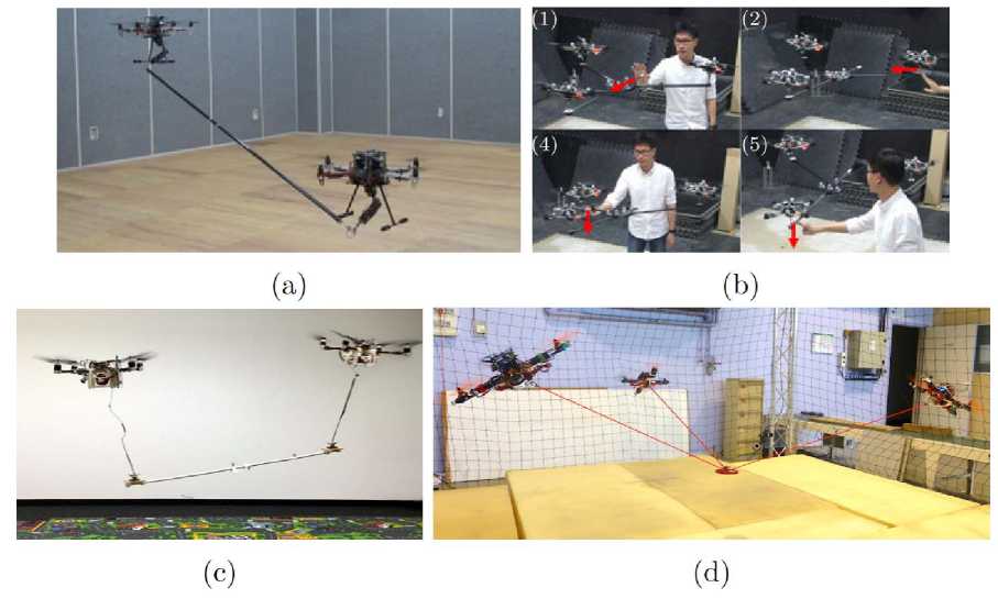
Fig. 32. Cooperative manipulations: (a) performed with two AMs; (b) performed using rigid links attached through spherical joints to a pay-load; (c) performed using cables and a vision-based approach based on a leader-follower scheme; (d) performed using cables [23]
One first line of works embraces cooperative manipulations performed through two or more AMs (Aerial Manipulators) that consist of aerial vehicles equipped with multi-DoFs arms. In such scenarios, high precision of payloads’ pose control can be obtained. Nevertheless, simultaneously managing the highdimensional dynamics of the entire systems and the interactions with the environment and the objects still represent a considerable challenge.
Aerial vehicles can also be used as distributed actuators. Solutions where multiple quadrotors have been rigidly attached to the objects. However, in such cases, the manipulation has been much demanding to obtain than the transportation. Such shortcoming is caused by the under-actuation property of the multi-rotors, especially when all the rotors are parallel. To overcome such limitations, the combination of rigid links attached through spherical joints to the payload has resulted reliably effective as demonstrated in [4,5] guaranteeing the full actuation of the platform handled by the robots. Moreover, if the rigid links are replaced with cables, flexible floating transportation structures can be designed. One of the interesting features is that such cables allow to partially decouple the rotational dynamics of the vehicle w.r.t. the one of the carried payloads. In addition, the robots’ payload capacity significantly increases due to their lightweight and the robot formation shapes become more flexible, provided that spherical joints are employed.
Although the community has been focusing on the topic for a while now, it is still in the process of studying the problem of the cable-suspended transportation/manipulation investigating models, developing suitable planning tool and control strategies.
However, in all the mentioned works the orientation of the payload was not fully controlled. For this reason, in the following, special attention will be devoted to solutions where the full manipulation of objects performed by flying cable-suspended systems is addressed (Fig. 33).
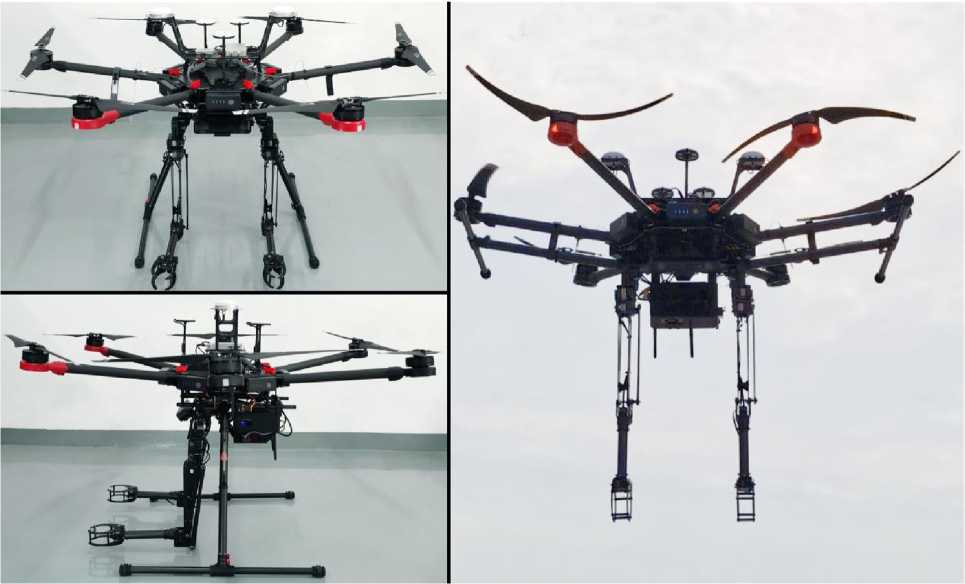
Fig. 33. Example of flying cable-suspended system with two-arms aerial manipulators [4,5]
Flying robots are being integrated in an ever-increasing set of applications such as inspection, surveillance, or even physical interaction and manipulation. However, aerial robots still present a set of key limitations. Largely, existing MAV designs are monolithic and thus present a common set of trade-offs, for example between payload and endurance or size. In the domain of aerial manipulation this implies rather sensitive designs with limited work-task execution capacity or resorting to large, complex and expensive platforms. Responding to a subset of these needs, reconfigurable and multilinked systems-of-systems of aerial robots have emerged including recent contribution on the Aerial Robotic Chain (ARC). Multilinked aerial systems such as the ARC can exploit a different design space and achieve simultaneously the ability to cross narrow sections, ferry significant payloads, enable distributed sensing and processing, incorporate redundancy and more. It is possible extend the potential of ARC by developing a custom aerial manipulation solution and proposing the modeling framework and control strategy that allow forceful physical interaction for work-task execution.
The proposed design extension of the aerial robotic chain, called “Aerial Robotic Chain Manipulator” (ARC-M) is a multilinked robot consisting of two quadrotors (ARC-units) connected, using 3 DoF) joints, through a rigid link that incorporates a manipulator with a lightweight finger end-effector. Figure 34 depicts the system [24].
Through its design, ARC-M presents a set of capabilities, including the ability to a) exert strong forces and moments, b) carry and lift significant payloads, and c) navigate narrow cross sections. Contrary to the majority of aerial manipulator designs where a single aerial robot is the basis for the overall force and moment exertion, ARC-M can apply significantly stronger moments and forces due to its ability to use the thrust vectoring of two independent quadrotors that are connected at a distance to each other and from the endeffector.
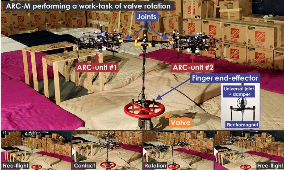
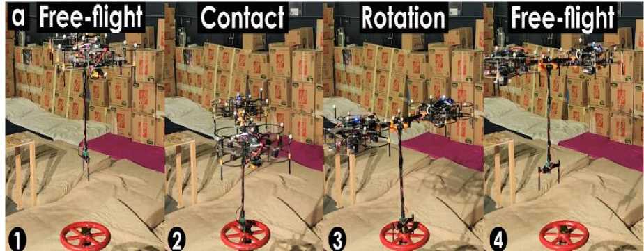
Fig. 34. The Aerial Robotic Chain Manipulator (ARC-M) performing a work-task involving forceful valve rotation (up); (a) valve rotation experiment: a) sequence of ARC-M poses (1,4: Free-flight, 2,3: Aerial Manipulation)
The first experiment, illustrated in Fig. 34, demonstrate the ability of ARC-M to perform forceful worktask execution such as opening or closing an industrial valve. The ARC-M first operates in Free-flight mode to traverse to the location of the valve. The controller then switches to the Aerial Manipulation mode when the finger end-effector is attached to the valve by an electromagnet. The two ARC-units cooperate to exert a significant yaw moment to rotate the valve by tilting around their roll axes, leveraging the length of the connecting link. The electromagnet is then turned off to detach the finger end-effector from the valve and the ARC-M switches back to Free-flight control to stabilize the roll and pitch angles of the link around zero.
Proceeding with the dichotomy of the two proposed approaches, this section is devoted to the specific model prototype of the Fly-Crane, which has been manufactured and then tested in real indoor scenarios. Starting from the mechanical details, the Fly-Crane consists of three Quadrotor UAVs connected by six cables to a platform made of carbon fiber bars. The Fly-Crane system while flying in an indoor scenario is shown in Fig. 35.
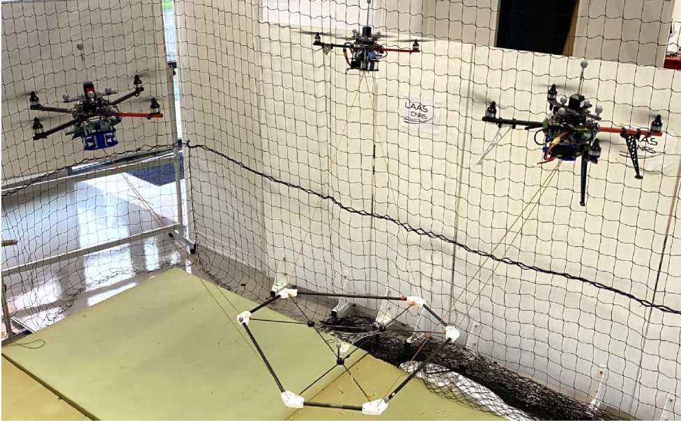
Fig. 35. Experimental screenshot of the Fly-Crane flying while controlling the platform in full pose (position and orientation)
In the first phase of each experiment, the platform is lifted from the ground, and the system is brought to a non-singular initial configuration. The aerial vehicles are independently controlled by a standard position controller.
Next experiment further showing the manipulation capabilities of the G-Fly-Crane (Fig. 36). This test emulates a structure decommissioning where bricks have to be removed from the inclined wall. As in the first experiment, the operator takes off and drives the G-Fly-Crane on top of the target brick.
Before descending to perform the pick, the pilot steers the platform to reach an orientation in accordance with the inclination of the brick. The brick can be then removed from the wall in a safe and accurate way, thanks to the dexterity provided by the G-Fly-Crane.
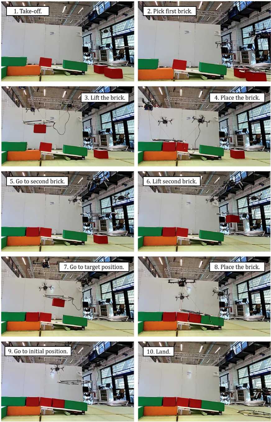
Fig. 36. Snapshots of the wall construction task with the G-Fly-Crane, illustrating the different phases
Unexpected-collision interaction experiment is designed to test the capability of the proposed aerial manipulation system to react stably to unexpected collisions and to adapt its behavior to such interactions (Figs 37 and 35).
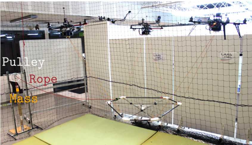
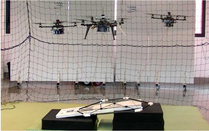
Fig. 37. The real-case scenario where the Fly-Crane has to approach a tilted surface being compliant with it
Additionally, the experiments also test the capabilities of the three aerial vehicles to maintain the cables’ tightness despite the contacts. To this end, a surface is placed in the middle of the arena, obstructing the way to the platform. the goal of all the previous experiments was to assess the well-thought selection of methods that allowed us to solve the aforementioned problems for the control of the Fly-Crane while physically interacting with the environment [24].
Aware that the employed algorithms are well known in the robotics community, especially in the context of ground manipulators, the challenge has been to endow the particular CS-AMRM under exam with such techniques facing all the possible obstacles that we could encounter.
-
I.3. Brain – computer interface in cognitive robotics control
In recent years, myoelectric control systems have emerged for upper limb wearable robotic exoskeletons to provide movement assistance and/or to restore motor functions in people with motor disabilities and to augment human performance in able-bodied individuals. In myoelectric control, electromyographic (EMG) signals from muscles are utilized to implement control strategies in exoskeletons and exosuits, improving adaptability and human–robot interactions during various motion tasks. The state-of-the-art myoelectric control systems designed for upper-limb wearable robotic exoskeletons and exosuits, and highlights the key focus areas for future research directions from intelligent cognitive robotic can be considered [25-27].
The upper extremity system simulates the working principle of muscles and tendons to generate power at the shoulder, elbow or wrist, which assists the upper arm, forearm or hand to perform specific movements or pick up loads. Several representative exosuits are shown in Fig. 38.
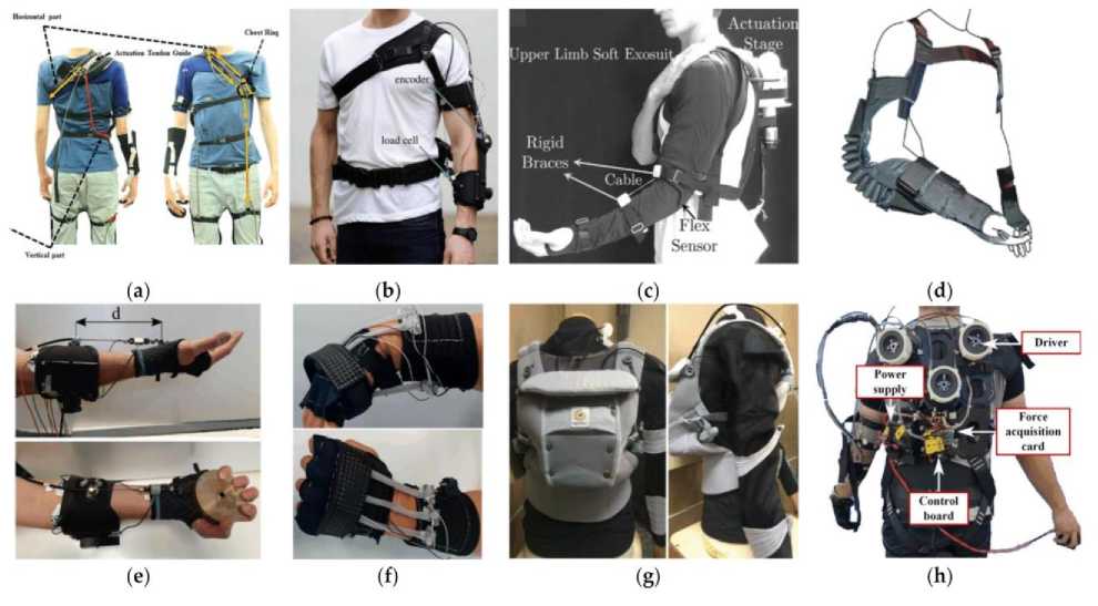
Fig. 38. Exosuits for upper limbs: ( a ) Unpowered shoulder exosuit for supporting weight and relieving muscle fatigue; ( b , c ) Wearable devices based on Bowden cables for elbow assistance; ( d ) Pneumatic exosuit for load holding and carrying; ( e ) Cable-driven device for wrist flexion; ( f ) Wearable robot using shape memory alloy; ( g ) An exosuit with a combination of different textiles through force-compliant sewing; ( h ) A cable-driven prototype to assist shoulder flexion/extension, shoulder adduction/abduction, and elbow flex-ion/extension [27]
There are significant differences in the anatomical structures and movement patterns for each joint. Different assistance schemes should be carefully evaluated according to specific application requirements.
The main objective of these control methods is to operate the system successfully under different disturbances generated from external environment. In case of exoskeleton robot, the objective of traditional control concept had further extended into consider the human motion intention. This is one of the interesting aspects of control methods of exoskeleton robot and one form of human biological signal called electromyography (EMG) has satisfactorily employed in some of designs. Most of EMG based control methods used with exoskeleton robots are in binary (on-off) nature. EMG signals indicate the firing rate of motor neurons and it is proportional to the muscle activity levels. Therefore, EMG signals directly reflect the motion intention of the human. However, in real practice, the measure of motor neuron activity is not an easy task. The measurement of EMG signals is carried out in two ways, using surface-EMG electrodes or using intramuscular EMG electrodes. Latter one gives the better muscle activation pattern than that of surface EMG electrodes. However, the EMG based control is not easy to realize due to various reasons. All EMG related parameters are subject - dependent and can be changed from day to day due to varying conditions of the skin and body size.
Control methods of upper-limb exoskeleton robots can be classified in several ways: based on input signals to the controller, based on controller architecture (configuration), based on output from the controller and other ways. The classification is carried out based on the input signals to the controller since controller input is very much significance for the performance of the control method. Based on input to the controller, the control methods can be categorized into control method based on human biological signal, control method based on non-biological signal and platform independent control method.
Figure 39 shows the ways of classification of the control methods.
Control methodilogies for upper limb exoskeleton robots input
biological signal non biological signal
configuration dynamic model muscle model on off control
output
current voltage
other
Proportional control Proportional+Derivative Proportional+Derivative+Integral Fuzzy, Neuro-fuzzy, Impedance and admittance control
-
Fig. 39. Classification of control methodologies of upper-limb exoskeleton robots
Figure 40 shows the classification of control methods of upper-limb exoskeleton robot based on input signals.
Control system classifiaation based on input signal
|
Based on human |
Based on non |
1 Platform |
|
biological |
biological |
independant |
|
signals |
signals |
control methods |
-
Fig. 40. Classification of control methodologies based on input signals
The demand for wearable robotic exoskeletons, more specifically upper limb rigid wearable robotic exoskeletons and soft wearable robotic exosuits, has substantially grown over the past few decades due to their promising applications across industry, and the medical and military sectors. The exoskeletons contain rigid links and joints attached to the user’s body, while exosuits use soft, flexible materials (such as fabric or soft polymer) to interface with the user’s body. The intended application scenarios for upper limb exoskeletons and exosuits include: (i) power augmentation to enhance physical performance or the capabilities of ablebodied individuals during strenuous or repetitive physical tasks, (ii) assisting individuals with disabilities in performing activities of daily living (ADLs), and (iii) the rehabilitation of patients with neuromuscular disorders through therapeutic exercises.
Myoelectric Control Systems for Upper Limb Wearable Robotic Exoskeletons and Exosuits. The myoelectric control systems of upper limb exoskeletons are based on surface electromyography (EMG) signals, which are the electric potentials directly measured from skeletal muscles and that are generated from motor unit activation. The generation of EMG signals is controlled by the human brain through motion intention, and is regulated by motor neurons in the spinal cord (Fig. 41), which offers a means for detecting the human motion intention before initiating a motion [25].
Muscle Fiber
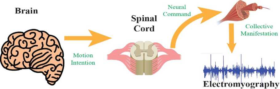
Fig. 41. The generation of electromyography signal corresponding to the muscle contraction
Compared to other control systems, the critical advantage of myoelectric control is its timely detection of the user’s motion intention leveraging electromechanical delay; the onset of motion intention can be detected about 50–100 ms earlier than the physical motion, giving time to control the upper limb wearable robotic exoskeletons to allow for more adaptive and intelligent human–robot interactions. The early stages of myoelectric control modalities for upper limb exoskeletons were based on on-off/finite state control and proportional control. Although they are fast, reliable, and applicable for real-time operation, the number of movements generated by these controllers is limited.
Therefore, they have been mostly utilized in supporting simple upper limb functions such as elbow flexion / extension or power grip. Recent advancements in machine learning (ML) and deep learning algorithms have made it possible to decipher more complex movements over multiple DOFs (such as shoulder motions) by extracting useful features from s-EMG signals. Although they have shown promising results in supporting complex, multi-DOF upper limb motions, their development is still in the early phase.
The controller of the robot consists [28] with two stages (Fig. 42), first stage, input signal selection and second stage, EMG based impedance control. Impedance parameters, B (damping coefficient) and K (spring constant) are adjusted online according to the upper-limb posture and its activity level.
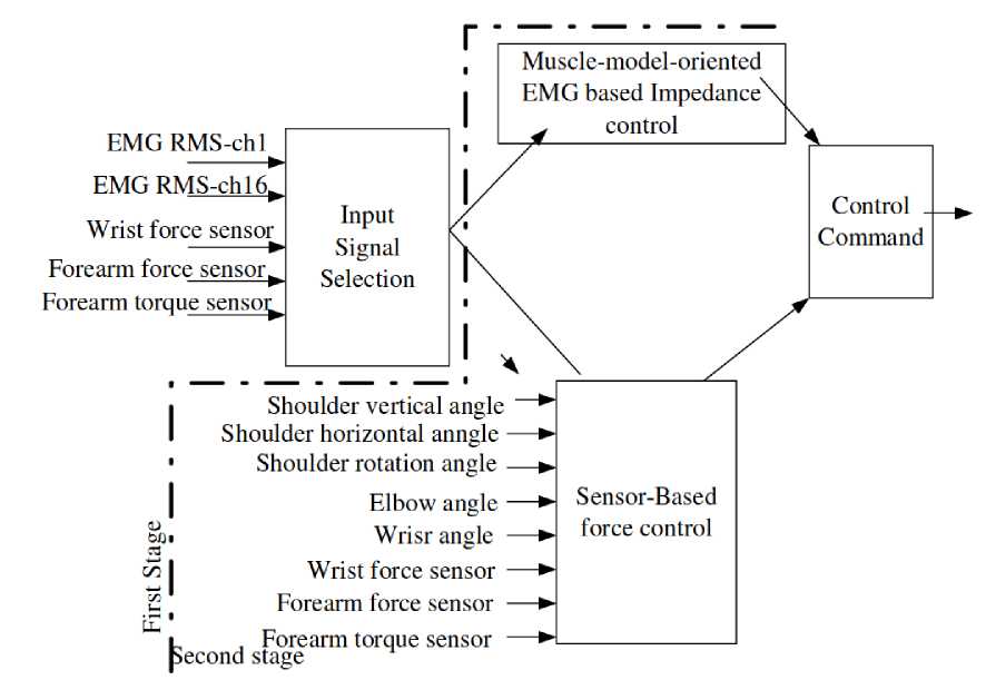
EMG RMS-chl
EMG RMS-chl6,
Wrist force sensor
60»
Forearm torque sensor —►■
L n Fore pecond stage
Sensor-Based force control
Input
Signal Selection
Forearm forc e sensor ^ Forearm torqu e sensot^
Muscle-model-oriented EMG based Impedance\ control
Shoulder vertical angle
Shoulder horizontal anngle —► Shoulder rotation angle —►
Elbow angle —►
Wrisr angle —►
Wrist force sensor —► Forearm force sensor —►
Control . Command
Fig. 42. Structure of control method of SUEFUL
Since torque varies with posture changes, online adaptation of neuro-fuzzy modifier is proposed. This online adaptation provides smooth operation to the robot. On the other hand, this adaptation needs to train the neuro-fuzzy modifier and it takes considerable time.
The results show that exoskeleton could provide extra torque indicating effective reduction of effort spent by subject or movement generation. Therefore, this proportional control method enabled to assist motion according to the level of need of the user. Further, this method can be improved by incorporating neuro-fuzzy controller to identify the level of torque needs according to the position of upper-limb and posture changes.
EMG based fuzzy-neuro control method is used in the SUEFUL (Fig. 42), which is designed for upper limb motion assist for physically weak persons. In addition to EMG signals, force/torque sensor signals of robot is also used as input signal to controller. When EMG signal level is low, force/torque signal is used to control the robot, while EMG control is used when EMG signal has high strength. Therefore, this avoids error motion cause by low level EMG and unexpected motion cause by external forces.
Fuzzy “if-then” rules are constructed to control motions of shoulder, elbow, forearm and wrist and those are transferred to fuzzy-neuro controller to determine the output of the controller. Total often fuzzy-neuro controllers are designed for generate the motion in forearm and wrist.
Fig. 43 shows the one of such fuzzy-neuro controllers used in robot. The weight of controller is adjusted according to error back propagation learning algorithm. This weight adjustment enables adaptation of weights for different situations caused by change of physical and psychological conditions of user.
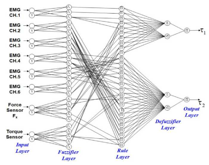
Fig. 43. EMG based fuzzy-neuro controller
The machine learning approach has been employed in upper limb exoskeletons to predict the movement pattern from EMG signals using various modalities. Such modalities of the myoelectric control system use the statistical features of the preprocessed EMG signals, such as root mean square (RMS), wave length (WL), and mean absolute value (MAV) as inputs to different machine learning models, detecting the type of movement via classification model, measuring the arm’s joint angle or joint torque via regression model, and minimizing muscle effort during assistance with reinforcement learning (as shown in Fig. 44).
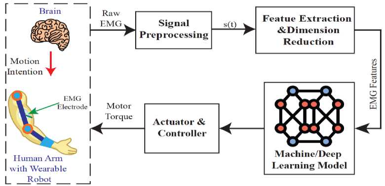
Fig. 44. The conceptual block diagram for deep learning/machine learning model-based myoelectric control system
The neural-fuzzy-based myoelectric control system is another scheme for controlling an upper limb exoskeleton-type exoskeleton. According to the theory of modern artificial intelligence, neural fuzzy is defined as the combination of a neural network and fuzzy logic. The fuzzy logic outputs the control command while the neural network tunes the fuzzy logic iteratively, which allows for training of the fuzzy logic during use (i.e., fuzzy modifier) (as shown in Fig. 45).
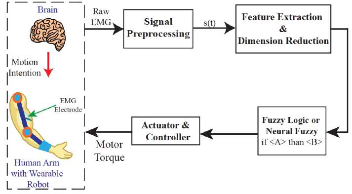
Fig. 45. The conceptual block diagram for neural-fuzzy-/fuzzy-logic-based myoelectric control system
The neuro-fuzzy myoelectric control system includes the fuzzy logic consisted of “IF
However, the notable downside of this approach is that the fuzzy logic becomes complicated as the number of DoFs of the exoskeleton increases. When a exoskeleton has multiple DoFs, the number of fuzzy logics will increase exponentially, consequently increasing the difficulty in implementing and training fuzzy logics [29,30].
Brain-computer interface (BCI) analyzes brain signals to understand intention and status of human that can be used for controlling various machines. Since brain signals contain significant information about status of human, many BCI studies have attempted to understand brain signals. In contrast, invasive methods such as electrocroticogram (ECoG) place the electrodes on the brain directly to acquire high-quality brain signals. These methods can obtain the higher quality of brain signals compared with non-invasive methods such as electroencephalogram (EEG), functional near-infrared spectroscopy (fNIRS), and functional magnetic resonance imaging (fMRI), but they are riskier because they involve surgery to implant electrodes.
EEG-based BCI has several paradigms for signal acquisition such as motor imagery (MI), event-related potential (ERP), and movement-related cortical potential (MRCP). As applications of EEG-based BCI, a robotic arm, a speller, a wheelchair, and a drone] were commonly used for communication between human and machines. The result was received with the convolutional type neural network application without any preprocessing and with an accuracy higher than 80% and an average time response of 42 . 21 ms. Processing of electroencephalographic (EEG) signals obtained by brain-to-computer interfaces (BCI), with which a series of commands will be generated to send orders to a drone. To achieve this, a structure is proposed as shown in Fig 46, in which the signals taken from the brain are passed to a compute.
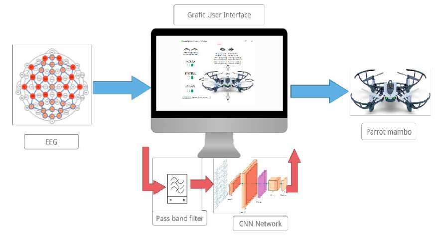
Fig. 46. Overview of the prototype [29]
To achieve the objective, it is suggested to use the motor execution paradigm, making use of actions that tend to be discarded because they are sometimes taken by artifacts (electrical potential not originated in the brain being blinks and eyebrow raising intentional by the user. For this purpose, the electrodes are distributed according to the international standard 10/20, seeking to cover the greatest amount of information in the motor areas of the cerebral cortex, taking advantage of the overlapping of the signals due to the fact that the electrodes are located on the scalp in the positions: Fp1, Fp2, C3, C4, Cp5, Cp6, Fc5, Fc6, F7, F8, Fc1, Fc2, T3, T4, Cp1, Cp2 and biauricular references (SDR left ear and BIAS right ear). The electrodes used are dry electrodes of silver chloride silver (Ag-AgCl) mounted on the Ultracortex Mark IV which send the signals to the Cyton and Deisy modules of the OpenBCI company with a sampling frequency of 125Hz.
Recently, a BCI-based drone swarm is one of the most interesting topics (Fig. 47).
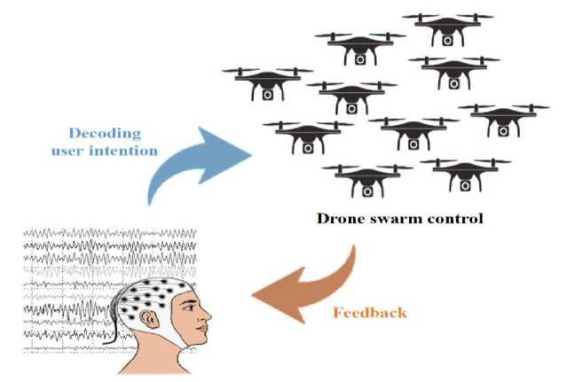
Signal acquisition
Fig. 47. The example of a brain-swarm interface for drone control [30]
EEG signals were acquired using 64 Ag/AgCl electrodes following 10/20 international systems.
The ground and reference channels were FCz and FPz positions, respectively. The sampling rate was 1,000 Hz, and a notch filter was applied to the acquired signals as 60 Hz. All electrode impedances were kept below 10 k during the experiment (Fig. 48).
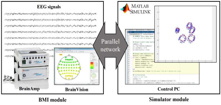
Fig. 48. System architecture for EEG data acquisition with a drone swarm simulator environment
A drone swarm control simulator using Matlab software (MathWorks, USA) with Mobile Robotics Simulation Toolbox. This toolbox provides utilities for robot simulation and algorithm development in the 2D grid maps. A multi-robot lidar control to drone swarm control system was composed of fifty unit drones. The drone conducted four different scenarios such as ‘Hovering’, ‘Splitting’, ‘Dispersing’, and ‘Aggregating’ through the simulator (Fig. 49).

Fig. 49. The example representation of a drone swarm simulator for four different scenarios
The hovering cue indicated an initial position of the swarm drone. The subjects imagined the visual instruction for the hovering state of drones. The splitting cue showed that the swarm drone divided two different swarms. The dispersing cue represented randomly position of each unit drone with outspreading. Finally, the aggregating cue indicated the unit drones was positioned closely with each other. One of the scenarios showed to the subjects during the ‘Visual cue/preparation’ phase. Therefore, through the experiment system, the subjects could perform the visual imagery for the drone swarm control of various scenarios.
Quantum Neural Networks application in intelligent drone control . The structure of quantum neural networks (QNN) comprises the state encoder, parametrized quantum circuit (PQC), and the measurement layer [31-34]. Since classical data X is incompatible with quantum circuits, it must be converted into quantum states before being used as input data. The data reuploading [35] method will be used in implementing the state encoder as shown in Fig. 50.
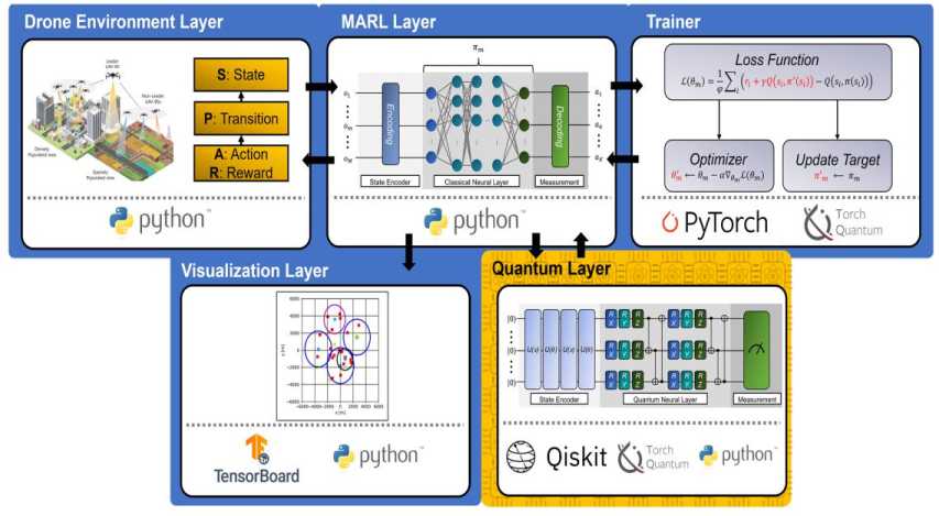
Fig. 50. The illustration of visual simulation software for quantum multi-drone reinforcement learning [36]
[The blue and yellow blocks indicate that each block utilizes classical computing, and quantum computing, respectively.]
Data reuploading and quantum state encoding are jointly achieved by passing q number of |0) qubits through a sequence of unitary operation gates containing the information of X and trainable parameters of the encoder, denoted as 0enc . In order to imbue each gate with information of X , it has to be split into [ xx,...,xN ] . Then, these gates will repeatedly rotate the initial qubits, and the output quantum states pro-
Сетевое научное издание «Системный анализ в науке и образовании» Выпуск №1, 2023 год duced successfully convert X into quantum states. The process of state encoding can be expressed as follows, I V enc^ = U ( P n ) U ( x N ).. . U ( 9 ) U ( x )| V o) , where N is the number of split data, U ( • ) represents a unitary operation of qubit rotation, V o) is the initial quantum state, | V c) is the encoded qubit and 9 is the trainable parameters of the state encoder. The PQC will then process the converted qubits. As shown in Appendix 4, the PQC is composed of the R x , R y , R z and the CNOT gates which contain trainable parameters 9PQc . By rotating and entangling the input qubits, we will be able to obtain the values needed for multi-agent reinforcement learning ( MARL).
Remark . Similar to the frameworks introduced MARL, a QMARL software framework designed for visualizing a multi-drone communication environment. The MARL framework is a hybrid model which utilizes both classic and QC. Classical computing is used to implement the Trainer in Fig. 50, which computes the loss function, performs optimization via gradient descent, and updates the target values. QC is used to implement the quantum-based policy (Q-policy) in Q-policy Layer, which computes the action distribution of all the agents. In this process, the data re-uploading technique encodes both classical data and compute output data. Leveraging QC in proposed model has not only increased the computational speed exponentially but also shown a higher total reward value after training. Therefore, the proposed model outperforms the previous model and other benchmarks, corroborating the methodology’s efficiency. Moreover, it is possible analyze multi-agent training processes and results thanks to proposed visual simulation software.
This can be expressed as | V pqc ) = U ( 9 q c)| Venc^ . Finally, the produced qubits will proceed into the measurement layer, where they will be measured. Measurement can be carried out by applying a projection matrix M e M = { Mx,...,Mc,...,Mc } onto the z - axis. The value produced from this operation is known as observable, denoted as. The measurement operation can be expressed as the following equation: VV 9 6Hf V)„ = <0| U * ( x ) U * ( 9 ) M c U (9)U ( x )|0) = V I M e I V >.
The observable produced from the quantum layer is the action distribution of the actors and is used to calculate the loss function. However, the loss function cannot be trained by backpropagation because quantum states within the QNN cannot be measured and will collapse when the chain rule is applied. Therefore, training is carried out by computing the loss gradient from the symmetric difference quotient of the loss function. Figure 50 illustrates the overall proposed framework of quantum MARL (QMARL). For this case agents try to learn a policy that maximizes the total reward. Let us describe the sequential framework of quantum MARL based on Fig. 50.
In Drone Environment Layer, all M agents collect observation information denoted as the set of states, which is S = [ ox ,..., om,...,oM ] . With agents’ state, they take actions in time step t based on their policy (i.e., actor), and then the state is transitioned to next time step t + 1 in MARL Layer. Here, all actions and rewards that agents take are denoted as the following sets, A = [ ax,..., am,..., aM ] and R = [ rx,...,rm,...,rM ] . Loss value is calculated by criticizing the reward that agents get at time step t with the return by target actor network in Trainer Layer.
After that, the optimizer updates the parameters of actor networks in the direction of decreasing the value of the loss function. In the case of the target network, its parameters are updated at a specific time intermittently.
The Quantum layer, also known as the Q-policy network, produces the action distribution of all the agents by taking the state data as input. The output data is computed by the encoders and parameterized quantum circuits which are the components of the Q-policy network. Then, the action distribution values will be used to calculate the loss function utilized in the trainer layer via the mean squared error function. Finally, the gradient of the loss function is calculated to perform gradient descent to update the actor parameters and the target.
At the same time, all agent’s trajectories are visualized while training their policies by tensor board in the visualization layer. Each agent has our proposed Q-policy as shown in Fig. 51.
The algorithm for the Q-policy network is shown in Fig. 51a. Firstly, (Lines 4–5) initialize the input dimensions as the size of the observation data of the agents and the initial quantum state dimension as the output size equivalent to the total number of actions. Next, (Line 6) defines the quantum device where the encoders and quantum layers will be placed. (Lines 7–9) and (Line 14) define the encoder and quantum layer, respectively. As shown in the figure, the encoder is composed of the pre-defined general encoder and re-uploading encoder, while the quantum layer is made up of Controlled U 3 gates. In (Line 10), the number of repetitions of data re-uploading is set as the ceiling value of the input dimension divided by the number of initial qubits. (Lines 11–13) define the parameter values of the Controlled U 3 gate. Finally, (Line 16) defines the measurement layer as applying Pauli- Z gate to all the qubits within the circuit. Fig. 51a contains the code for the forward function of the Q-policy network. (Lines 19–20) show the process of reshaping the input data into a single-column matrix. Then, (Line 21) is the part where data re-uploading occurs.
class QPolicy(tq.QuantumModule):
input_dim, output_dim):
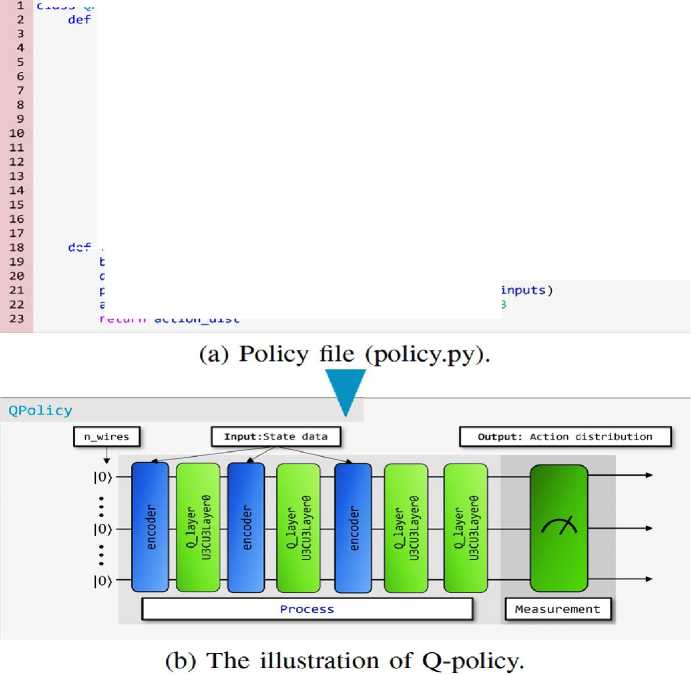
Fig. 51. Quantum Layer
= input_dim
= output_dim
= tq .QuantumDevice(n_wires = self.n_wires)
= [tq.GeneralEncoder(enc_dict['6_ryJ]),\ tq.ReuploadingEncoder(enc_dict['6_ryJ]), \ tq.ReuploadingEncoder(enc_dict['4_ry’])]
= {'n_wires': self.n_wires,\
'n_blocks': 3,\
'n_layers_per_block': 3}
data = inputs.reshape(bsz, -1)
process(self,q_device, self.encoder, self.q_layer, i action_dist = self.measure(self.q_device) * 3
return action dist
The process is repeated for the number of repetitions initialized above. Every iteration passes the input data through one encoder and one quantum-layer (Q-layer). Note that the first and the last iterations use encoders with different input dimensions. Lastly, (Lines 22– 23) return the action distribution by measuring the output produced by data re-uploading. Figure 51 also shows the structure of the Q-policy network, which is designed to perform data reuploading. As shown in the Fig. 51, data re-uploading passes an initial quantum state through a repeated sequence of encoders and Q-layers. According to the algorithm elaborated above, the quantum gates in the encoders are imbued with the input state data. At the same time, the Q-layer is made up of Controlled U 3 gates containing parameters such as the number of blocks, the number of layers per block, and the number of qubits. After data re-uploading has been pe. I.51rformed, the output quantum state is measured by projecting the quantum state onto the reference z -axis to obtain the action distribution data.
Each agent is given a unique identification to distinguish agents and created two neural networks corresponding to the agent’s policy; actor-network and target actor-network. Using the target network, the learning process becomes more stable by making the target value independent to the training parameters in actor- network. The optimizer updates the parameters of actor networks to decrease the value of the loss function by Trainer in Fig. 50.
All results show the common tendencies, where agents in the classical MARL get larger values in the intermediate step of learning and a faster increase rate in the early step of learning. However, users in the QMARL get more considerable value at the end of the training. In other words, proposed QMARL shows a more stable convergence rate with little fluctuations and higher values at the end of the learning.
It is possible also observe agents’ trajectories while learning their policies in Fig. 52a–c, where all agents try to provide high-quality wireless communication service to.
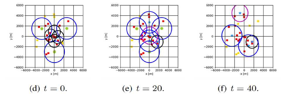
Fig. 52. Various aspects of results for evaluating performance in each training method [36]
[The blue and red represent the learning results in proposed QMARL and classical MARL, respectively.]
When there is no malfunctioning, agents move to areas where any drone doesn’t provide service to users. Conversely, when any malfunction occurs, the agents move to areas where the malfunctioned non-agent has provided service to users. By our proposed visual simulation software framework, we can validate that the QMARL can make a reasonable performance with a smaller number of trainable parameters compared to classical MARL in reward convergence and system quality.
Main problem of AI robotic systems as the creation of smart robust knowledge bases for robotic interacting groups in this textbook is considered. This technology of quantum intelligent controllers in MLIT JINR is developed [32,33].
References Quantum software industrial engineering and intelligent cognitive robotics in industry 4.0 as control objects - prototypes of industry 5.0 / 6.0 models: introduction
- Chen B. et al. Smart Factory of Industry 4.0: Key Technologies, Application Case, and Challenges // IEEE Access. – 2018. – No 6. – Pp. 6505 – 6519.
- Havard V. et al. Digital twin and virtual reality: a co-simulation environment for design and assessment of industrial workstations // Production & Manufacturing Research. – 2019. –Vol. 7. –No 1. –Pp. 472-489. –DOI: 10.1080/21693277.2019.1660283.
- Huang Z. AI-Driven Digital Twins // Sensors. – 2021. – No 21. – Pp. 6340. – DOI: 10.3390/s21196340.
- Tyatyushkina O., Ulyanov S. Intelligent cognitive control of robotic sociotechnical systems. Pt.1: Ro-botic systems and «Human being - robot» interactive models in project «Industry 4.0» // System Analy-sis in Science and Education. – 2021. – No 3. – Pp. 44–101. – URL: http://sanse.ru/download/447.
- Ulyanov S. V. Intelligent cognitive control of sociotechnical robotic systems. Pt. 2: Nonlinear model generation of intelligent cognitive robotics for project “Industry 4.0” // System Analysis in Science and Education. – 2021. – No 3. – Pp. 1–43. – URL: http://sanse.ru/download/449.
- Alcácer V., Cruz-Machado V. Scanning the Industry 4.0: A Literature Review on Technologies for Manufacturing Systems // Intern. J. Eng. Sci. and Technol. – 2019. – Vol. 22. – Pp.899 – 919. – DOI: 10.1016/j.jestch.2019.01.006.
- Pegman G. Leading European Robotics: Robotic Visions to 2020 and beyond – The Strategic Research Agenda for robotics in Europe. Industrial Technologies Conference Brussels. – Belgium, 2020.
- Bhirangi R. et al. All the Feels: A dexterous hand with large area sensing // arXiv:2210.15658v1 [cs.RO] 27 Oct 2022.
- Berscheid L. et al. Robot Learning of 6DoF Grasping using Model-based Adaptive Primitives // arXiv:2103.12810v1 [cs.RO] 23 Mar 2021.
- Liu J. et al. Robot Cooking with Stir-fry: Bimanual Non-prehensile Manipulation of Semi-fluid Objects // arXiv:2205.05960v1 [cs.RO] 12 May 2022.
- Lv J. et al. SAM-RL: Sensing-Aware Model-Based Reinforcement Learning via Differentiable Physics-Based Simulation and Rendering // arXiv:2210.15185v1 [cs.RO] 27 Oct 2022.
- Marinho M.M. et al. Design and Validation of a Multi-Arm Robot Platform for Scientific Exploration // arXiv:2210.11877v1 [cs.RO] 21 Oct 2022.
- Shi B. et al. Robust Control of a New Asymmetric Teleoperation Robot Based on a State Observer // Sensors. – 2021. – Vol. 21. – Pp. 6197. – DOI: 10.3390/s21186197.
- Cui Z. et al. Caveats on the first-generation da Vinci Research Kit: latent technical constraints and essential calibrations // arXiv:2210.13598v1 [cs.RO] 24 Oct 2022.
- Giberti H. et al. A Methodology for Flexible Implementation of Collaborative Robots in Smart Manu-facturing Systems // Robotics. – 2022. – Vol. 11. – No 9. – DOI: 10.3390/ robotics11010009.
- Kasaei H., Kasaei M. Throwing Objects into A Moving Basket While Avoiding Obstacles // arXiv:2210.00609v1 [cs.RO] 2 Oct 2022.
- Ulloa C. et al. A Mixed-Reality Tele-Operation Method for High-Level Control of a Legged-Manipulator Robot // Sensors. – 2022. – Vol. 22. – Pp. 8146. – DOI: 10.3390/s22218146.
- Xia K. et al. Towards Semantic Integration of Machine Vision Systems to Aid Manufacturing Event Understanding // Sensors. – 2021. – Vol. 21. – Pp. 4276. – DOI: 10.3390/s21134276.
- Tyatyushkina O.Yu., Ulyanov S.V. Unmanned Aerial Vehicles. Pt. 1: Bio-inspired and aerial–aquatic locomotion // System analysis in science and education. – 2022. – No 3. – Pp. 8-52. – URL : http://sanse.ru/download/473.
- Tyatyushkina O.Yu., Ulyanov S.V. Unmanned Aerial Robotic Vehicles. Pt. 2: Unconventional models of unmanned aerial systems and aerial embedding manipulators // System analysis in science and educa-tion. – 2022. – No 3. – Pp. 53-109. – URL : http://sanse.ru/download/474.
- Mohiuddin A. et al. A survey of single and multi-UAV aerial manipulation // Unmanned Systems. - 2020. – Vol. 8. - No 2. – Pp. 119-147. DOI : 10.1142/S2301385020500089.
- Ollero A. et al. Past, Present and Future of Aerial Robotic Manipulators // IEEE TRANSACTIONS ON ROBOTICS. – 2022. – Vol. 38. – No. 1. – Pp. 626-645.
- Sanalitro D. Aerial Cooperative Manipulation: full pose manipulation in air and in interaction with the environment. - DOCTORAT DE L‟UNIVERSITÉ FÉDÉRALE TOULOUSE MIDI-PYRÉNÉES. l‟Institut National des Sciences Appliquées de Toulouse (INSA de Toulouse), 2022.
- Huan N., Kostas A. Forceful Aerial Manipulation based on an Aerial Robotic Chain: Hybrid Modeling and Control // IEEE Robotics and Automation Letters. – 2021. – Vol. 6. – No 2. – Pp. 3711-3719. – DOI : 10.1109/LRA.2021.3064254.
- Fu J. et al. Myoelectric Control Systems for Upper Limb Wearable Robotic Exoskeletons and Exosuits - A Systematic Review // Sensors. - 2022. - Vol. 22. - Pp 8134. – DOI : 10.3390/ s22218134.
- Gull M.A. et al. A Review on Design of Upper Limb Exoskeletons // Robotics. – 2020. – Vol. 9. – No 16. – DOI : 10.3390/robotics9010016.
- Shi, Y. et al. Soft Wearable Robots: Development Status and Technical Challenges // Sensors. – 2022. – Vol. 22. – Pp. 7584. – DOI : 10.3390/s22197584.
- Gunasekara J.M. et al. Control Methodologies for Upper Limb Exoskeleton Robots // IEEE/SICE Inter-national Symposium on System Integration (SII) Kyushu University, Fukuoka, Japan December 16-18, 2012. – 2012. – Pp. 19-24. – DOI : 10.1109/SII.2012.6427387.
- Villegas I. Recognition and Characteristics EEG Signals for Flight Control of a Drone // IFAC Paper-sOnLine. – 2021. – Vol. 54 – No 4. – Pp. 50–55.
- Jeong J-H. et al. Towards Brain-Computer Interfaces for Drone Swarm Control // arXiv:2002.00519v1 [cs.NE] 3 Feb 2020.
- Tyatyushkina O. Yu., Reshetnikov A.G., Ulyanov S. V. Intelligent cognitive robotics. Vol. 1: Soft computational intelligence and information-thermodynamic law of intelligent cognitive control. – M.: Kurs, 2022.
- Кореньков В.В., Ульянов С.В. Интеллектуальная когнитивная робототехника. Ч. 1: Технологии квантовых когнитивных вычислений. – М.: Курс, 2022.
- Ulyanov S.V. Intelligent cognitive robotics. Vol. 2. – M.: Kurs, 2022.
- Ivancova O.V., Korenkov V.V., Ulyanov S.V., Zrelov P.V. Quantum soft engineering toolkit. Pt I. – M.: Kurs, 2022.
- Perez-Salinas A. et al. Data re-uploading for a universal quantum classifier // Quantum. – 2020. – Vol. 4. - Pp. 226.
- Park C. et al. Visual Simulation Software Demonstration for Quantum Multi-Drone Reinforcement Learning // arXiv:2211.15375v1 [quant-ph] 24 Nov 2022.
