Radiation Characteristics Enhancement of Microstrip Triangular Patch Antenna using Several Array Structures

Author: Hayat Errifi, Abdennaceur Baghdad, Abdelmajid Badri, Aicha Sahel
Journal: International Journal of Wireless and Microwave Technologies(IJWMT) @ijwmt
Article in issue: 3 Vol.5, 2015.
Free access
In the recent years the development in communication systems requires the development of low cost, minimal weight and low profile antenna that is capable of maintaining high performance over a wide spectrum of frequencies. This technological trend has focused much effort into the design of a microstrip patch antenna. The aim of this paper is to design and simulate a triangular microstrip patch array antenna using HFSS software and compare the performance of 2 elements, 4 elements and 8 elements patch arrays with that of a single patch for the same operating frequency. Also comparisons are made between the performance of series, corporate and series-corporate feed network. These arrays are designed to operate at a frequency of 11 GHz. Our goal is to obtain a high directivity with better gain and reduced losses, to be especially used for X band applications such as satellite communication, radar, medical applications, and other wireless systems.
Microstrip triangular patch antenna, array antenna, corporate-series feed, corporate feed, series feed, microstrip line feed, return Loss, directivity
Short address: https://sciup.org/15012895
IDR: 15012895
Text of the scientific article Radiation Characteristics Enhancement of Microstrip Triangular Patch Antenna using Several Array Structures
Published Online May 2015 in MECS DOI: 10.5815/ijwmt.2015.03.01
The importance of wireless communication and multimedia services is increasing the efforts of design and implementation of novel microstrip patch structures from miniaturized electronic circuits to the antenna arrays [1, 2].
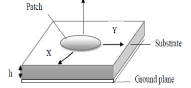
Microstrip patch antennas have found extensive application in wireless communication system due to their advantages such as low profile, conformability, low-cost fabrication and ease of integration with feed network. Microstrip antenna in its simplest form consists of a radiating patch (of different shapes) which is made up of a conducting material like Copper or Gold on one side of a dielectric substrate and a ground plane on the other side, Fig 1.
* Corresponding author. Tel.: 06 63 53 47 74
The conducting patch can take any shape, but rectangular, triangular and circular configurations are the most commonly used configurations. This antenna is used in communication systems due to simplicity in structure, conformability, low manufacturing cost, and very versatile in terms of resonant frequency, polarization, pattern and impedance at the particular patch shape and model [3], it can be used for high frequency and high speed for data transfer.
Substrate
Ground plane
Fig.1. Microstrip patch antenna geometry
In various communications and radar systems, microstrip array antennas are greatly desired. They are used, to synthesize a required pattern that cannot be achieved with a single element. In addition, they are used to scan the beam of an antenna system, increase the directivity, and perform various other functions which would be difficult with any one single element [4]. The elements can be fed by a single line or by multiple lines in a feed network arrangement. The first is referred to as a series-feed network while the second is referred to as a corporate-feed network [3]. This paper presents the characteristic of microstrip triangular patch array antennas, series-feed, corporate feed and their combination. The rest of the paper is organized as follows: Section 2 explains the design of microstrip triangular patch antenna and section 3 is about the design procedures for Microstrip patch array antenna using series, corporate and series-corporate feed network. Section 4 deals with the simulation set up with results and discussions in addition to the analysis of a comparative performance for better understanding. Section 5 gives conclusion and anticipated future work.
-
2. Microstrip Triangular Patch Antenna Design
8.791X10
The equilateral length of the triangular patch is given by [3]:
2C 3FV^r
Where F =
Inset length of the patch for inserting microstrip feed line is [4-5-6]:
Y0= 10 -4 [0.001699 sr 7 + 0.13761 sr 6 - 6.1783 sr5 + 93.187 sr 4 - 682.69 sr3 + 2561.9 sr2 - 4043 sr1 +
6697] | this expression is valid for 2 < sr < 10.
The patch equilateral length (a) has been calculated as (15 mm) and for ground plane dimension has been calculated as (35 mm×27 mm).
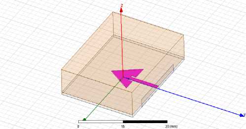
Where λ is the wave length, fr is the resonant frequency, c is the speed of light in free space, and εr is the dielectric constant of the substrate.; In the following Fig.2 shows a single triangular patch antenna that has been designed to cover operating frequency of 11 GHz with input impedance of 50 Ω, using RT-DURROID (εr = 2.2) and height (h=0.79mm) [7].
-
Fig.2. Single element triangular patch antenna
-
3. Microstrip Patch Array Antennas Design
-
3.1. Software tools
-
3.2. Feed network
Microstrip antennas are used not only as single element but also very popular in arrays. Main limitation of microstrip is that it radiate efficiently only over a narrow band of frequencies and they can’t operate at the high power levels of waveguide, coaxial line, or even strip-line [5]. This can be minimized with the help of various array configurations [8], feeding methods [4], dielectric materials [9, 10, and 11] and ground planes. Antenna arrays are used to scan the beam of an antenna system, to increase the directivity, gain and enhance various other functions which would be difficult with single element antenna.
The software used to model and simulate the microstrip patch array antennas is HFSS. HFSS is a high-performance full-wave electromagnetic (EM) field simulator for arbitrary 3D volumetric passive device modeling that takes advantage of the familiar Microsoft Windows graphical user interface. It integrates simulation, visualization, solid modeling, and automation in an easy-to-learn environment where solutions to your 3D EM problems are quickly and accurately obtained. Ansoft HFSS employs the Finite Element Method (FEM), adaptive meshing, and brilliant graphics to give you unparalleled performance and insight to all of your 3D EM problems. Ansoft HFSS can be used to calculate parameters such as S-Parameters, Resonant Frequency, and Fields [12].
In the microstrip array, elements can be fed by a single line or multiple lines in a feed network arrangement [3, 8]. Feeding methods are classified as:
-
• Series feed network
-
• Corporate feed network
-
• Corporate-series feed network.
-
3.3. Microstrip 2×1 patch array antenna design
The series feed usually consists of a continuous transmission line from which small proportion of energy are progressively coupled into the individual element disposed along the line. The series feed constitutes a traveling wave array if the feed line is terminated in a matched load. Fig (3.a). Here the difference between the series feed and corporate feed. A corporate feed is most widely used parallel feed configuration. For a uniform aperture distribution, the power is equally split at each junction. However different power divider ratios can be chosen to generate a tapered distribution across the array. The disadvantages of this type of feed is that it requires long transmission lines between radiating elements and the input port hence the insertion loss of the feed network can be prohibitively large thereby reducing the overall efficiency of the array. Fig (3.b). The series-corporate feed is the combination of series feed and corporate feed; it is frequently used for array antennas [13] to get benefits of both feeding networks. In this paper the series, corporate and series corporatefeed with inset feed is being discussed for the antenna array design. When feeding is bed, the total efficiency could be reduced to a low level which makes the whole system to be rejected.
The effects of the feed network are important in high gain microstrip antenna array with large number of radiating elements and complicated feed network [14-15].
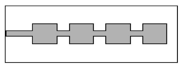
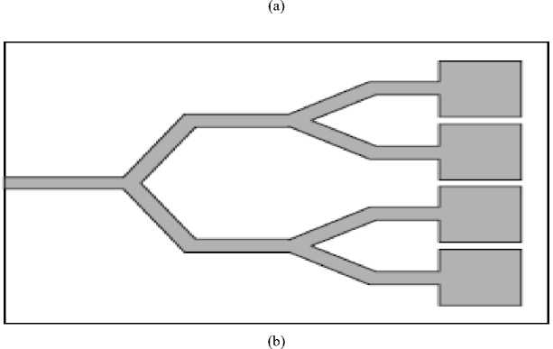
Fig.3. (a) Series feed, (b) Corporate feed
Using the same dimensions and a spacing of λ/2 between the patch elements, an array of 2 triangular patches is designed. We opted for two feeding methods, once is series feed using a quarter wavelength transformer and the other is corporate feed through a network of microstrip line in the form of T-junction (power divider) excited by source 50 Ω. Figures (4, 5) shows the proposed antennas.
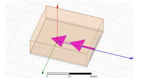
Fig.4. Triangular 2×1 patch array antenna with series feed
Fig.5. Triangular 2×1 patch array antenna with corporate feed
-
3.4. Microstrip 4×1 patch array antenna design
To design a 4×1 triangular patch array antenna, series feed, corporate feed and series-corporate feed networks are used as shown in figures (6, 7, 8) respectively. Here 4 elements are used and each element has the same dimensions as mentioned above in order to increase the antenna performance. In this design, the patch elements are connected using quarter wavelength microstrip line in series feed and T- junction power divider is used in corporate feed. The structure of the power divider is symmetric. The spacing between the patch elements is λ/2.
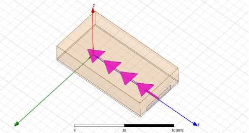
Fig.6. Triangular 4×1 patch array antenna with series feed
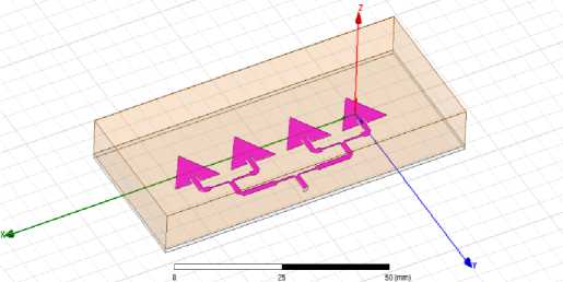
Fig.7. Triangular 4×1 patch array antenna with corporate feed
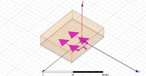
Fig.8. Triangular 2×2 patch array antenna with series-corporate feed
-
3.5. Microstrip 8×1 patch array antenna design
Using the same dimensions mentioned above and a spacing of λ/2 between the patch elements, an array of 8 triangular patches is designed. Series feed, corporate feed and series-corporate feed networks are used respectively as shown in figure (9, 10, and 11). The patch elements are connected using a quarter wavelength microstrip lines in series feed and T- junction power dividers are used in corporate feed and both for seriescorporate feed. The structure of the power dividers is symmetric.
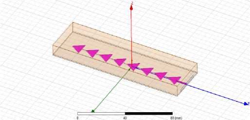
Fig.9. Triangular 8×1 patch array antenna with series feed
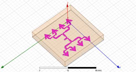
Fig.10. Triangular 8×1 patch array antenna with corporate feed
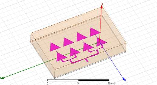
Fig.11. Triangular 8×1 patch array antenna with series-corporate feed
-
4.1. Microstrip single patch antenna
Now-a-days, it is a common practice to evaluate the system performances through computer simulation before the real time implementation. HFSS simulator [12] also helps to reduce the fabrication cost because only the antenna with the best performance would be fabricated.
-
a) Return loss
Figure 12 shows the return loss simulated for microstrip single triangular patch antenna. This antenna resonates at frequency of: 10.6 GHz, with return loss -14.33 dB.
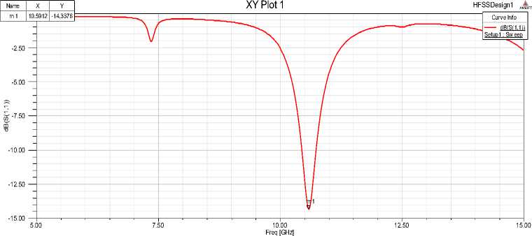
Fig.12. Return loss of single triangular patch antenna
-
b) Gain and directivity
The simulated gain and directivity of the antenna, according to fig 13, 14, are 8.09dB and 8.49 dB respectively at φ = 0_ for the operating frequency. The beam-width is about 65°.
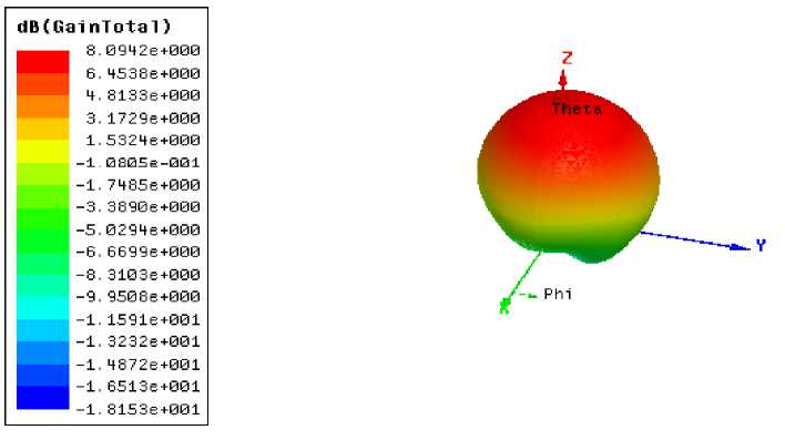
Fig.13. 3D polar plot of single triangular patch antenna
|
Name |
Theta |
Ang |
Mag |
|
m1 |
0.0000 |
0.0000 |
8.4944 |
HFSSDesign1 ANSOFT
Radiation Pattern 1
-90
-180
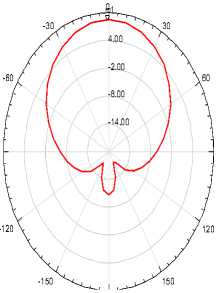
Fig.14. Radiation pattern of single triangular patch antenna
From these results we can say that proposed antenna don’t exploit well the X-band.
-
4.2. Microstrip 2×1 patch array antenna
-
a) Return loss
S parameter calculation has been performed for microstrip 2x1 patch array antenna with series and corporate feed network. The center frequency is selected as the one at which the return loss is minimum. Fig 15 shows that the return loss for patch array antenna with series feed is -11.97 dB at frequency 11.91 GHZ and for corporate feeding the return loss is about -19.50 dB at frequency 11.41 GHZ.
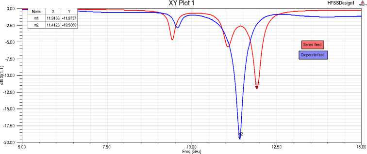
Fig.15. Return loss of the 2-elements series and corporate feed antenna array
The return loss is lower in corporate feed; therefore antenna efficiency is higher at this method of feeding.
-
b) Antenna parameters
Some of antenna parameters, such as the gain, directivity and 3 dB beam width for 2x1 patch array antenna series/ corporate feed are tabulated below. From the table 1, it is clear that gain, directivity and beam-width of 2x1 phased array antenna with corporate feed are better than those of series feed.
Table 1. Parameters of 2x1 patch array antenna series and corporate feed
Antenna parameters Microstrip 2×1 patch array antenna
Series feed Corporate feed
Gain 9.61 dB 9.93dB
Directivity 9.94 dB 10.23 dB
Beam width 68° 43°
-
c) Radiation pattern of designed antennas
The radiation pattern of an antenna is important in determining most of the characteristics which include beam- width, beam shape, directivity and radiated power.
|
Name Theta Ang Mag m1 0.0000 0.0000 9.9406 -60 -90 -120 Name Theta Ang Mag m1 0.0000 0.0000 10.2317 -60 -90 -120 |
Radiation Pattern 1 HFSSDesign1 ANSOF m01
-8.00 \ \ \ -14.00 \ { 90 120
Radiation Pattern 1 HFSSDesign1 ANSOFT 0
- . 60 -16.00 -28.00 90 120
|
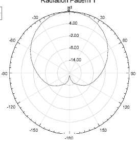
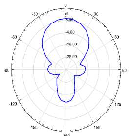
Fig.16. Radiation pattern of the 2-elements antenna array
It can be observed clearly that the radiation beam of corporate feed array antenna is narrow and more directive than that of series feed.
-
4.3. Microstrip 4×1 Patch Array Antenna
-
a) Return loss
S parameter calculation has been performed for microstrip 4x1 patch array antenna with series, corporate and series-corporate feed network. The center frequency is selected as the one at which the return loss is minimum. Fig 17 shows that the return loss for patch array antenna with series feed are -15.06 dB at frequency 11.81 GHZ. For corporate feeding the return loss is about -21.23 dB at frequency 11.59 GHZ and -25.88 dB at frequency 11.91 GHZ for series-corporate feed.
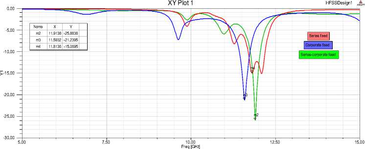
Fig.17. Return loss of the 4-elements series, corporate and series-corporate feed antenna array
According to the figures above, it was observed that with the variation of feed network, the resonant frequency does not shift much, but the return loss show a considerable change; it reaches a minimum value for series-corporate feed network.
-
b) Antenna parameters
Some of antenna parameters, such as the gain, directivity and 3 dB beam width for 4x1 patch array antenna series, corporate and series-corporate feed are tabulated below. From the table II, it is clear that gain and directivity of 4x1 phased array antenna with corporate feed are better than those of series and series-corporate feed.
Table 2. Parameters of 4x1 patch array antenna series, corporate and series-corporate feed
|
Antenna parameters |
Microstrip 4×1 patch array antenna |
||
|
Series feed |
Corporate feed |
Series-corporate feed |
|
|
Gain |
9.49dB |
12.57dB |
11.87dB |
|
Directivity |
10.74dB |
13.00dB |
12.41dB |
|
Beam width |
54° |
22° |
41° |
-
c) Radiation pattern of designed antennas
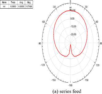
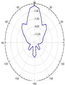
The representation of radiation pattern of 4×1 patch array antenna excited by series, corporate and seriescorporate feeding is shown in fig 18.
HFSSDesign1 ANSOFT
Radiation Pattern 1
Radiation Pattern 1
Name Theta Ang Mag m1 0.0000 0.0000 13.0022
(b) corporate feed
HFSSDesign1 ANSOFT
HFSSDesign1 ANSOFT
Name Theta Ang Mag m1 0.0000 0.0000 12.4179
Radiation Pattern 1
-90
-180
(c) series-corporate feed
Fig.18. Radiation pattern of the 4-elements antenna array:
It can be observed clearly that array antenna with corporate feed has a narrow beam width comparing with other methods of feeding networks. We also noted the minimization of secondary lobes.
-
4.4. Microstrip 8×1 Patch Array Antenna
-
a) Return loss
In this part S parameter calculation has been performed for microstrip 8x1 patch array antenna with series, corporate and series-corporate feed network. Fig 19 shows that the return loss for patch array antenna with series feed is -15.79 dB at frequency 12 GHZ. For corporate feeding the return loss is about -4.00 dB at frequency 11.11 GHZ and -13.37 dB at frequency 11.91 GHZ for series-corporate feed network.
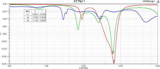
Fig.19. Return loss of the 8-elements series, corporate and series-corporate feed antenna array
We note that return loss increased for corporate feed compared to series feed and this is due to the feeding network that contains more microstrip lines causing more losses.
-
b) Antenna parameters
Some of antenna parameters, such as the gain, directivity and 3 dB beam width for 8x1 patch array antenna series, corporate and series-corporate feed are tabulated below. From the table III, it is clear that gain and directivity of 8x1 phased array antenna with series-corporate feed are better than those of series and corporate feed.
Table 3. Parameters of 8x1 patch array antenna series, corporate and series-corporate feed
|
Antenna parameters |
Microstrip 8×1 patch array antenna |
||
|
Series feed |
Corporate feed |
Series-corporate feed |
|
|
Gain |
12.54dB |
12.5dB |
14.24dB |
|
Directivity |
13.32dB |
13.32dB |
14.96dB |
|
Beam width |
73° |
- |
21° |
When the patch number increases, the feeding network becomes more complicated and radiation efficiency decreases that is why it is better to make a combination between a series and corporate feed to facilitate the design and improve the radiation efficiency by reducing the number of micro strip lines.
-
c) Radiation pattern of designed antenna
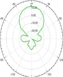
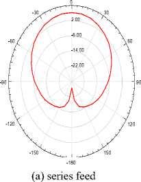
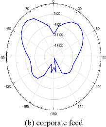
The representation of radiation pattern of 8×1 patch array antenna excited by series, corporate and seriescorporate feeding is shown in fig 20.
HFSSDesign1 ANSOFT
Radiation Pattern 1
Radiation Pattern 1
HFSSDesign1 ANSOFT
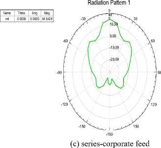
Fig.20. Radiation pattern of the 8-elements antenna array
HFSSDesign1 ANSOFT
It can be observed clearly that array antenna with series-corporate feed represents improvement in radiation pattern; it has a narrow beam-width comparing with other methods of feeding networks.
-
d) Comparative analysis
-
5. Conclusion
Simulation results obtained for single patch antenna and 8 elements array antenna with series-corporate feed are presented in this table:
Table 4. Comparison between single patch antenna and 8x1 patch array antenna series-corporate feed network
|
Single patch antenna |
8x1 patch array antenna series-corporate feed |
|
|
Dimension |
3.5×2.7 cm2 |
4.8×8 cm2 |
|
Resonance frequency |
10.6 GHz |
11.91 GHz |
|
Return loss |
-14.33 dB |
-13.37dB |
|
Gain |
8.09 dB |
14.24 dB |
|
Directivity |
8.49 dB |
14.96 dB |
|
Beam width |
65° |
21° |
We can see from table above much improved result is achieved with 8×1 patch array antenna seriescorporate feed network as compared to other arrays. Regarding to return loss we got almost the same curve of single element, the radiation pattern is more directive it has the beam-width 21° at ϕ=0.
The unique feature of this microstrip antenna is its simplicity to get higher performance. In many applications basically in radar and satellite communication, it is necessary to design antennas with very high directive characteristics to meet the demand of long distance communication and the most common configuration to satisfy this demand is the array form of the microstrip antenna.
For an array antenna with a large number of patches, the gain and directivity increase whatever the feeding method (series, corporate or series-corporate) however observing the performance analysis of the three of these array antennas, it is convenient to say that 8x1 patch array antenna with series-corporate feed network provides better performance than the other arrays, -13.37 dB return loss and 15 dB directivity is achieved at 11.9 GHz.
The microstrip 8x1 patch array antenna with series-corporate feed has the small size, the higher directive gain as well as the narrow beam width (21° at φ = 0) which seem to be suitable criteria to design a directive patch antenna for radar system.
Here designed array antennas covers 11 GHz operating frequency and it would also be possible to design the bands, operating any other system such as in WLAN, WIMAX, WBAN or other wireless systems, by changing the dimension of the patch element.
Acknowledgements
References Radiation Characteristics Enhancement of Microstrip Triangular Patch Antenna using Several Array Structures
- Shagun Maheshwari, Priyanka Jain, Archana Agarwal 《CPW-FED WIDEBAND ANTENNA WITH U-SHAPED GROUND PLANE》. I.J. Wireless and Microwave Technologies (IJWMT). ISSN: 2076-1449(PRINT), ISSN: 2076-9539(ONLINE).Volume 5, November 2014.
- Kehinde Odeyemi, Erastus Ogunti 《PERFORMANCE COMPARISON OF BEAMFORMING AND MULTIPLEXING TECHNIQUES USING SMART ANTENNA ARRAY》 I.J. Wireless and Microwave Technologies (IJWMT).ISSN: 2076-1449(PRINT), ISSN: 2076-9539(ONLINE).Volume 3, October 2014.
- C. A. Balanis, Antenna Theory: Analysis and Design, 3rd ed, 2005. H. Errifi, A. Baghdad, A. Badri, A.Sahel 《DESIGN AND SIMULATION OF MICROSTRIP PATCH ARRAY ANTENNA WITH HIGH DIRECTIVITY FOR 10 GHZ APPLICATIONS》 International Symposium on Signal Image Video and Communications, ISIVC-2014, 19-21 November 2014, Marrakech, Morocco.
- H. Errifi, A. Baghdad, A. Badri, A.Sahel 《EFFECT OF CHANGE IN FEEDPOINT ON THE ANTENNA PERFORMANCE IN EDGE, PROBE AND INSET-FEED MICROSTRIP PATCH ANTENNA FOR 10 GHZ》. International Journal of Emerging Trends in Engineering and Development (IJETED). ISSN NO.:2249-6149. Volume 1, January 2014.
- R. Garg, Microstrip Antenna Design Handbook, Boston, Mass. [u.a.]: Artech House, 2001.
- M.Ramesh, YIP KB 《 DESIGN FORMULA FOR INSET FED MICROSTRIP PATCH ANTENNA 》.Journal of microwave and optoelectronics, Volume 3, No. 3, pp. 5-10, ISSN 1516-7399, Motorola, Pinang, Malaysia, December 2003.
- H. Errifi, A. Baghdad, A. Badri, A.Sahel 《GENETIC ALGORITHM OPTIMIZATION AND PERFORMANCE COMPARATIVE ANALYSIS OF RECTANGULAR, TRIANGULAR AND CIRCULAR PATCH ANTENNAS FOR X BAND APPLICATIONS》. International Journal of Engineering and Technology (IJET). ISSN NO: 0975-4024. Volume 7, Issue 2, April 2014. In press.
- H. Errifi, A. Baghdad, A. Badri 《DESIGN AND ANALYSIS OF MICROSTRIP PATCH ARRAY ANTENNA WITH SERIE, CORPORATE AND SERIE-CORPORATE FEED NETWORK》. International Journal of Electronics and Electrical Engineering (IJEEE).In press.
- H. Errifi, A. Baghdad, A. Badri, A.Sahel 《DIRECTIVITY ENHANCEMENT OF APERTURE COUPLED MICROSTRIP PATCH ANTENNA USING TWO LAYERS DIELECTRIC SUPERSTRATE》 14th Mediterranean Microwave Symposium, MMS-2014, 12-14 December 2014, Marrakech, Morocco.
- H. Errifi, A. Baghdad, A. Badri, A.Sahel 《ENHANCEMENT OF INSET FEED MICROSTRIP SEMICIRCULAR PATCH ANTENNA DIRECTIVITY USING DIELECTRIC SUPERSTRATE》 International Journal of Computer and Information Technology (IJCIT). (ISSN: 2279 – 0764). Volume-04, Issue 02, March 2015.
- H. Errifi, A. Baghdad, A. Badri, A.Sahel 《IMPROVING MICROSTRIP PATCH ANTENNA DIRECTIVITY USING EBG SUPERSTRATE》. American Journal of Engineering Research (AJER). E-ISSN: 2320-0847 p-ISSN: 2320-0936.Volume-03, Issue-11, November 2014.
- HFSS software user guide.
- M. I. Skolnik, Introduction to Radar Systems, 3rd ed, New York, McGraw-Hill, 2000.
- R.mailloux, et al., "Microstrip Array Technology", Antennas and propagation, IEEE transactions, vol.29, pp. 25-37, 1981.
- Md. Tanvir Ishtaique"ul Huque, Md. Kamal Hosain, Md. Shihabul Islam and Md. Al"Amin Chowdhury 《DESIGN AND PERFORMANCE ANALYSIS OF MICROSTRIP ARRAY ANTENNAS WITH OPTIMUM PARAMETERS FOR X BAND APPLICATIONS》. International Journal of Advanced Computer Science and Applications (IJACSA), Vol. 2, No. 4, 2011.
