Real-time Flame Rendering with GPU and CUDA

Author: Wei Wei, Yanqiong Huang
Journal: International Journal of Information Technology and Computer Science(IJITCS) @ijitcs
Article in issue: 1 Vol. 3, 2011.
Free access
This paper proposes a method of flame simulation based on Lagrange process and chemical composition, which was non-grid and the problems associated with there grids were overcome. The turbulence movement of flame was described by Lagrange process and chemical composition was added into flame simulation which increased the authenticity of flame. For real-time applications, this paper simplified the EMST model. GPU-based particle system combined with OpenGL VBO and PBO unique technology was used to accelerate finally, the speed of vertex and pixel data interaction between CPU and GPU increased two orders of magnitude, frame rate of rendering increased by 30%, which achieved fast dynamic flame real-time simulation. For further real-time applications, this paper presented a strategy to implement flame simulation with CUDA on GPU, which achieved a speed up to 2.5 times the previous implementation.
Fluid model, chemical composition, CUDA
Short address: https://sciup.org/15011606
IDR: 15011606
Text of the scientific article Real-time Flame Rendering with GPU and CUDA
Published Online February 2011 in MECS
The simulation of flame has been a challenging research topic in computer graphics in recent years. The difficulty for the accurate simulation of flame including irregularity of the flame shape, color variability, the complexity of the production of gas and other uncertain factors.
Reeves [1] proposed particle systems approach for fire simulation and other irregular objects in 1983. Dynamic fluid equation based on grid was proposed by Ferziger [2] as a method of flame simulation in computer graphics, which was complex and included large amount of calculation. The real-time simulation of flame was difficult to realize and the calculation based on gird was difficult to guarantee stability. Perlin adopted the definition of solid texture and added noise to achieve flame animation [3]. Ebert described a new technique which efficiently combined volume rendering and scan line [4]. Scott and his colleagues [5] presented a technique to animate amorphous materials such as fire、smoke and dust in real-time on graphics hardware with dedicated texture memory. Perry proposed the flame spread model in 1994 [6]. On this basis, Stam in 1995, proposed a thermodynamic simulation method of flame [7]. Wang Jizhou [8] presented a survey on the development of flame simulation in computer animation, with a detail introduction to the classification of the works as well as different kinds of methods employed in the field.
In November 2006, NVIDIA introduced CUDA™ [17], a general purpose parallel computing architecture – with a new parallel programming model and instruction set architecture that leverages the parallel compute engine in NVIDIA GPUs to solve many complex computational problems in a more efficient way than on a CPU. CUDA comes with a software environment that allows developers to use C as a high-level programming language.
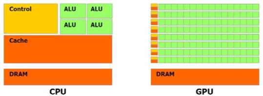
The reason behind the discrepancy in floating-point capability between the CPU and the GPU is that the GPU is specialized for compute-intensive, highly parallel computation – exactly what graphics rendering is about – and therefore designed such that more transistors are devoted to data processing rather than data caching and flow control. More specifically, the GPU is especially well-suited to address problems that can be expressed as data-parallel computations the same program is executed on many data elements in parallel with high arithmetic intensity, the ratio of arithmetic operations to memory operations. Because the same program is executed for each data element, there is a lower requirement for sophisticated flow control, and because it is executed on many data elements and has high arithmetic intensity, the memory access latency can be hidden with calculations instead of big data caches.
Data-parallel processing maps data elements to parallel processing threads. Many applications that process large data sets can use a data-parallel programming model to speed up the computations. In 3D rendering, large sets of pixels and vertices are mapped to parallel threads. Similarly, image and media processing applications such as post-processing of rendered images, video encoding and decoding, image scaling, stereo vision, and pattern recognition can map image blocks and pixels to parallel processing threads. In fact, many algorithms outside the field of image rendering and processing are accelerated by data-parallel processing, from general signal processing or physics simulation to computational finance or computational biology.
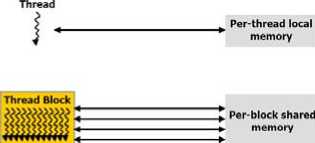
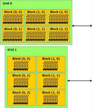
The advent of multi-core CPUs and many-core GPUs means that mainstream processor chips are now parallel systems. Furthermore, their parallelism continues to scale with Moore’s law. The challenge is to develop application software that transparently scales its parallelism to leverage the increasing number of processor cores, much as 3D graphics applications transparently scale their parallelism to many-core GPUs with widely varying numbers of cores. The CUDA parallel programming model is designed to overcome this challenge while maintaining a low learning curve for programmers familiar with standard programming languages such as C. At its core are three key abstractions a hierarchy of thread groups, shared memories, and barrier synchronization – that are simply exposed to the programmer as a minimal set of language extensions. These abstractions provide fine-grained data parallelism and thread parallelism, nested within coarse-grained data parallelism and task parallelism. They guide the programmer to partition the problem into coarse sub-problems that can be solved independently in parallel by blocks of threads, and each sub-problem into finer pieces that can be solved cooperatively in parallel by all threads within the block. This decomposition preserves language expressivity by allowing threads to cooperate when solving each sub-problem, and at the same time enables automatic scalability. Indeed, each block of threads can be scheduled on any of the available processor cores, in any order, concurrently or sequentially, so that a compiled CUDA program can execute on any number of processor cores as illustrated by Fig.1, and only the runtime system needs to know the physical processor count.
This scalable programming model allows the CUDA architecture to span a wide market range by simply scaling the number of processors and memory partitions: from the high-performance enthusiast GeForce GPUs and professional Quadro and Tesla computing products to a variety of inexpensive, mainstream GeForce GPUs .
Global memory
Fig 1. CUDA architecture based on GPU
-
II. FLAME MODELING
Flame can be seen as the procession of fuel reacts with oxygen, which releases light and heat. The movement of flame can be described into laminar and turbulent flow. Nguyen and his colleagues [9] simulated flame by hydrodynamic equations in 2002, which simulated the turbulence movement of flame more accurately.
The turbulence movement of flame can be defined by Mass Conservation equation and Navier-Stokes equation:
V- U = 0 ( 1 )
— = - - Vp + uV 2U + F (2) dt p
In above equations, U was the velocity vector; p was the fluid density; p was pressure; v was the dynamic viscosity; V was the Laplacian operator; F was the external forces that act on the fluid.
Equation (1) and (2) can be solved by Euler method, which used a fixed point of the grid for the definition of the velocity field. But in case of disordered flow, the chaotic characteristics of flow made the definition of grid size, shape, position, and resolution issues complex. The nonlinear equations of fluid spent a lot of computer system resources, which took a few seconds to render a frame.
In view of these problems, this paper proposed a method based on Lagrangian method without grid. In this method, the fluid was modeled by a set of particles. The statistical properties of these particles based on equations of fluid and were more stable in the numerical solution.
The following equation defined the changes of particles.
dX (i ) = U ( i ) dt (3)
du (i) = 4 C 0 < to > U ( i ) ( t ) -< U > dt + V C 0 k < to > dW (4)
Equation (3) defined the position of the particle according to the velocity, and velocity calculation based on the simplified Langevin model [10]. Equation (4) defined the frequency of the turbulence. to was the turbulence frequency and symbol <> represented the average. Constant C0 was a standard value of turbulent motion, and k was the disturbance kinetic energy, and dW was the increments of W(t) in Wiener equation. The turbulent movement of the flame can be modeled by (3) and (4) combined with particle system, which overcame the reality limitations of particle system for flame.
-
III. COMBUSTION COMPONENT
Flame modeling methods on the chemical composition were almost based on empirical researches. As lots of simplifying assumptions were made, the flame model was difference from the actual flame, which has its specific combustion mode, depending on many factors, including chemical composition, fuel diffusion, oxides and spawn. Subbramaniam and Pope [11] proposed the Euclidian Minimum Spanning Tree (EMST) mixing model for modeling chemicals of fire flame. The composition of particles was defined by thermal chemical model in EMST. The neighborhoods of tree nodes were used to update the chemical components, which helped maintain chemical composition with the development of combustion. EMST model was difficult for real-time simulation. Therefore, this paper proposed a simplified model for real-time applications.
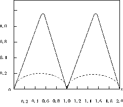
Fig 2. EMST model
In Fig. 2, x-axis represented the mixture fraction ^X’ t) ; y-axis was the variables of combustion composition Y(X,t). X represented particle's position vector (x1, x2, x3), and X represented the combustion coefficient. The time parameter could be removed to simplify the EMST model, and ^X’ t) can be я ^( X) t n Y (X, t)
expressed as . When t = 0, , can defined as follows:
Y(X,0) = Y(^(X))=exp(-(4(X)-L^(X) J)-0.5)2/X be
In the initial, the combustion composition of particles was spread in accordance with Gaussian distribution, as the solid line in Fig. 1. Then combustion components became stability and changed into the point of the curve lines. The change speed [12] depended on the different essentialities of combustions and can be described by equation (6).
Y ( X , t ) = ( x + rd )* Y ( X , t - 1) (6)
In (6), X was the decline rate of the reaction rd G [0,0.01* x] process variables, and was a small random perturbation. In the combustion process, when the fire intensity increased, the burning intensified. When the fire reduced and the intensity was insufficient to sustain the flame, the flame went out. An attenuation number was used to predict the development of the flame in EMST. Adabala used the average of the combustion component to simplify the EMST method [13].
-
IV. STRAIGHT RENDERING
Zhao Chunxia [14] proposed a flame model based on particle system, which discussed particle’s attributes in detail and emphasized the color variation and dynamic wavering of the flame . Li Jianming [15] based on physical model simulation for the calculation of the flame, high complexity and difficult problem in real-time simulation, proposed a fluid-based model and real-time GPU-accelerated simulation of the flame, but frequently data interaction between CPU and GPU affected the efficiency, and real-time rendering problem was not been fundamentally improved.
In order to ensure real-time rendering, an effective balance between the interaction and reality needed to establish. OpenGL VBO (Vertex Buffer Object) and PBO (Pixel Buffer Object) technology put the vertex and pixel data directly into video card in cache, which effectively reduced the time of the vertex and pixel data transfer between CPU and GPU and increased the rendering speed. PBO was asynchronous through DMA (Direct Memory Access) technology. The following two graphs compared with the traditional texture transfer and PBO process.
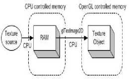
Fig 3. Traditional texture transfer
OpenGL controlled memory glTexlmage2D
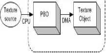
Fig 4. PBO process
Fig.3 showed the process that loaded the image data from image sources (such as image files and video) to the texture object with traditional method. Pixel data stored in the system memory first, and then used glTexImage2D to copy data from system memory to a texture object. CPU was occupied during the whole process. As shown in Fig. 3, the pixel data loaded into PBO directly, and only this process needed CPU to perform. GPU was in charge of the data transfer from PBO to texture object, without CPU involvement. Therefore, compared with Fig.3, glTexImage2D in Fig.4 returned immediately without immediately executed. Hence CPU can perform other operations without having to wait for the end of the pixel data transfer. More PBOs can be used in order to obtain greater performance. A test program was made to test the performance generated by PBO. Twenty sets of data for each state were selected and the average value was calculated, as shown in table 1.
Table 1. PBO performance test
|
State |
Parallel time ( ms ) |
Copytime ( ms ) |
Frame rate (fps) |
|
PBO OFF |
1.760 |
4.847 |
64.1 |
|
PBO ON |
3.789 |
0.046 |
83.4 |
|
2PBO ON |
4.206 |
0.054 |
82.8 |
Tests showed that the use of PBO technology can increase the pixel transfer speed for two orders of magnitude, thus greatly reduced data exchange time between CPU and GPU, and improved the frame rate of about 30%. More PBOs can increase the parallel computing time, but frame rate decreased slightly. Due to thermal buoyancy, particles had an upward initial velocity, but the particles changed with the turbulence which was not always upward. The particle properties rendered each frame, including Lagrangian properties and disordered movement of the combustion component attributes. The process of flame simulation algorithm was showed in Fig. 5.
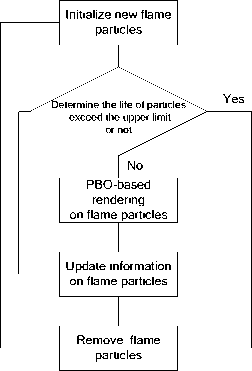
Fig 5. Flame simulation algorithm processes
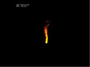
Fig 6 . Real-time flame simulation
The properties of each particle changed in terms of the turbulence movement and combustion component in every frame rendering. The simulation was based on OpenGL and VS2005 platform, in Intel core2.0 1.87 GHz, GeForce 7600 GS PC machine. Frame rate was around 60 FPS, which ensured smooth and real-time effects (Fig. 6).
-
V. PARALLEL RENDERING
In order to ensure real-time rendering, we implemented the parallel version of our technique using the NVIDIA CUDA [NVIDIA. 2009] language, which allows us to use the graphics processor without using shading languages. In the context of CUDA, the CPU plays the role of the Host, which controls the graphics processor and calls Device. It sends data, calls the Device to execute some functions, and then copies back its
results.
CUDA is parallel computing architecture. It enables dramatic increases in computing performance by harnessing the power of the GPU. Each graphics processor of an NVIDIA graphics card is divided into several multiprocessors. NVIDIA CUDA [NVIDIA. 2009] divides the processing in blocks, where each block is divided in several threads. Each block of threads is mapped to one multiprocessor of the graphics processor. When the CPU calls the Device to execute a function, it needs to inform how the work will be divided in blocks and threads. Maximum performance is achieved when we maximize the use of blocks and threads for a given graphics processor.
Each of the multiprocessors is a group of simple processors that share a set of registers and some memory, which is the shared memory space. The shared memory size is very small; usually 16KB or 32KB on graphics cards running on 1.3 compute capable device, but it is as fast as the registers. The communication between two multiprocessors must be done through the Device memory, which is quite slow if compared to the shared memory. There is also the Constant Cache and Texture Cache memory, which has better access times than the Device memory, but it is read-only for the Device. Before the execution of the code in the Device, CPU must send the data to its Device memory to be processed later. The memory copy from the Host (CPU) memory to the Device memory is a quite slow process, and should be minimized. Besides, the NVIDIA CUDA Programming Guide [16] says that one single call to the memory copy function with a lot of data is much more efficient than several calls to the same function with a few bytes. The performance of application can be improved by making good use of these restrictions of CUDA. To avoid several memory transactions between the Host (CPU) and the Device, all attributes in contiguous memory areas was stored together, and treat it like an array. At the position k stored an attribute of the particle Pk (Fig. 7). Proceeding in this way, several unnecessary copies were avoided, which improved the overall performance. Device memory can be allocated on a linear, but also can be assigned for the CUDA array form. CUDA memory can be 1 dimensional, 2 dimensional and 3D (2.0 version). Memory types included unsigned8, 16 or 32-bit int, 16-bit (only driver API can do) float, 32-bit float. This allocated memory can only process through kernel function in CUDA.
In order to verify that our parallel implementation can be executed faster than the sequential one, a couple of tests were accomplished. All the tests were executed in an Intel X5450 3.00GHz, NVIDIA Quadro FX 3700 graphics card.
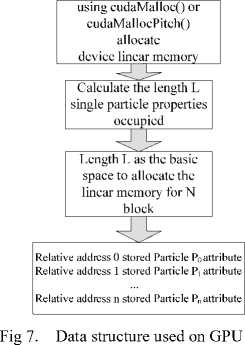
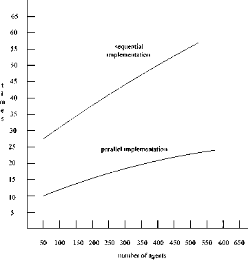
Fig 8. Speed up achieved using the parallel implementation over the sequential implementation.
The graphic in Fig.8 shows the speed up achieved using the parallel implementation over the sequential version of the technique. As we can see, test showed the parallel version was above more than twice faster than the sequential one (exactly the lowest point in the graphic is at 2.8 times). Besides that, sequential version with the agent increases, the time increased faster than parallel version.
In addition, according to the NVIDIA CUDA Programming Guide [NVIDIA. 2009], the graphics processor cannot handle all the data in a parallel way. The division of the work in blocks of threads lets the graphics processor scheduler run some blocks of thread while others wait for execution. Because of this, the computation of 256 local maps in a parallel way does not give a speed up of 256 times.
To explain what the cause of the graphics peaks is, the NVIDIA CUDA Programming Guide says that each algorithm implemented with CUDA has an optimal point, in which the amount of blocks and threads uses the most possible number of resources available in the graphics processor simultaneously.
This paper presented a strategy to implement flame simulation on GPU under CUDA Framework, which constitutes a great advantage when compared to the traditional method. We implemented a parallel version of this algorithm using the NVIDIA CUDA [NVIDIA. 2009] language, which allows us to use the graphics processor avoiding the use of shading languages. The parallelism was explored, reducing the amount of memory transactions between CPU and GPU. Our result shown that the GPU implementation improves up to 2.5 times the sequential CPU version.
As future work, the exploration of this method used on parallel architectures and explored the use of other shading languages. It would be interesting to compare the possible improvements in performance using other languages.
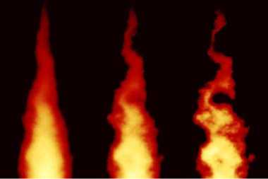
Fig 9. Parallel Flame Simulation
The properties of each particle changed in terms of the turbulence movement every frame rendering. Frame rate was around 60 FPS, which ensured smooth and real-time effects (Fig. 9).
-
VI. CONCLUSIONS
This paper presented a non-grid flame simulation method, which using Lagrangian process to describe the turbulence movement of the flame and a simplified EMST model to describe the combustion component. This method overcame the problems associated with the grid, such as grid size, grid resolution and grid position in space selection and generated the general state of flame simulation and had good foregrounds in field of computer animation and virtual reality. The speed of vertex and pixel data exchange between CPU and GPU was two orders of magnitude faster by using OpenGL VBO and PBO technology. For real-time applications, this paper presented a strategy to implement flame simulation with CUDA on GPU, which achieved a speed up to 2.5 times the sequential implementation. In further studies, smoke can be joined in flame simulation. In further studies, smoke can be joined in flame simulation.
References Real-time Flame Rendering with GPU and CUDA
- Reeves W T, “Particle systems-a technique fur modeling a class of fuzzy objects,” [J]. Computer Graphics(S0097-8930), 1983, 17(3): 359-376.
- Joel H. Ferziger, Milovan Peric. Computational Methods for Fluid Dynamics [M], third edition, Springer Press.
- Perlin K. An image synthesizer [J]. ACM Computer Graphics, 1985, 19(3): 287-296.
- Ebert D S, Richard E P. Rendering and animation of gaseous phenomena by combining fast volume and scan line A-buffer techniques [J]. ACM Computer Graphics, 1990, 24(4): 357-366.
- Scott A K, Roger A. Crawfis, Wayland Reid, "Fast Animation of Amorphous and Gaseous Phenomena", Volume Graphics '99, Swansea, Wales, pp 333-346, March 1999.
- Perry C H, Picard R. Synthesizing flames and their spread [C] Siggraph’94. Technical Sketches Notes, US, 1994.
- Stam J, Fiume Eugene. Depicting fire and other gaseous phenomena using diffusion processes [C], Computer Graphics Proceedings, Annual Conference Series, ACM SIGGRAPH, LosAngeles, US: ACM Press, 1995: 129-36.
- Wang Jizhou, Gu Yaolin. Flame Simulation Method of Review [J]. Journal of Image and Graphics, 2007, 12(11): 1961-1970. (in Chinese)
- Nguyen Duc Quang, Fedkiw Ronald, Jensen Henrik Wann. Physically based modeling and animation of fire [C]. ACM Transactions on Graphics(S0730-0301), 2002, 21(3):721-728.
- Pope, S. B. Turbulent Flows [M]. Cambridge: Cambridge University Press, 2000.
- Subramaniam, S. and S. B. Pope. A mixing model for turbulent reactive flows based on Euclidean minimum spanning trees [J]. Combustion and Flame, 1998, 115(4): 487-514.
- Lamorlette, A. and N. Foster. Structural modeling of natural flames [C]. Proceedings of ACM SIGGRAPH 2002, July 2002, 729-735.
- Adabala N, Manohar S. Modeling and rendering of gaseous phenomena using particle maps [J]. Journal of Visualization and Computer Animation,2000, (11) :279~293.
- ZHAO Chunxia, ZHANG Yan, ZHAN Shouyi. Three-dimensional particle-based fire simulation systems approach [J]. Computer Engineering and Applications:2004 (28). (in Chinese)
- Li Jianming, Wu Yunlong, Chi Zhongxian, He Rongsheng. GPU-based fluid model and the flame acceleration real-time simulation [J]. Journal of System Simulation : 2007(19). (in Chinese)
