Real-time realistic telepresence using a 360° camera and a virtual reality box

Author: Dan Vincent G. Alcabaza, Marvin E. Legaspi, Trisha Leinelle Muyot, Kate Louise C. Ofren, Johsua Angelo D. Panganiban, Roselito E. Tolentino
Journal: International Journal of Information Technology and Computer Science @ijitcs
Article in issue: 3 Vol. 11, 2019.
Free access
This study focuses on the transmission of live 360 video using Ricoh Theta S which is transmitted to Android phone mounted in BoboVR. The proposed solution is to use a 360 camera that captures the scene in all direction and create an application which streams the captured 360 live video from Laptop (Server) into the Android Phone (Client). The Android phone’s IMU sensor is responsible for the corresponding viewport selected from the 360 environment. The viewport is subject for Stereoscopic SBS to show the 3D effect in accordance with the user’s perception The viewport is subject for Stereoscopic SBS to show the 3D effect in accordance with the user’s perception. A 3D video can be produced by applying the Stereogram SBS. Also, depth can be perceived due to the varying distance between the focal baseline and focal length.
Real-Time, Telepresence, Virtual Reality, 360° Camera, Head Mounted Display
Short address: https://sciup.org/15016344
IDR: 15016344 | DOI: 10.5815/ijitcs.2019.03.05
Text of the scientific article Real-time realistic telepresence using a 360° camera and a virtual reality box
Published Online March 2019 in MECS
Telepresence has been described as the human experience of being fully present at a live real-world location remote from one's own physical location. It is having a sensation of being elsewhere due to technology. It is commonly used in conference meetings and in the inspection of places a human can’t enter. Because of these helpful applications, the accelerating growth of technology continues to develop telepresence make more immersive or realistic. In relation to telepresence, the user can experience being in a simulated environment, this is what we called virtual presence. A person using virtual reality equipment is able to "look around" the artificial world, and with high quality VR move about in it and interact with virtual features or items. Virtual reality is an artificial environment that is created with software and presented to the user in such a way that the user suspends belief and accepts it as a real environment.
In some studies, they have introduced the hardware configuration and software framework for the system and a method to calculate the homograph between the camera image space and user head image space. The head pose then is sent to the pan-tilt camera through the network as commands, and the camera responds by moving to the pose consistent with user’s head. But, they have experienced a problem involving black pixels in the output. Due to the panning of user, the transmission of the data takes up a lot of time. As a result, black pixels in the image will occur. Also, in other studies, involving a system structure that is composed of a mobile robot, a controller for the robot, and VR content. This contents share the robot’s vision by attaching the camera at a mobile robot that can control wireless controller of the wearable form using sensors such as a gyro sensor. This controls the motion by connecting to the wearable wireless controller and the mobile robot as well as playing the video. However, users experienced a shaky image. The proponents have made a solution to solve these provided problems. To achieve an exact image, without having a black pixel, the proponents figure out the use of omnidirectional camera. From “omni” meaning all, an omnidirectional camera captures an all direction view (360 degree) in a single shot, thus, having a name “360 camera”. Many 360 cameras capture a full 360 degree at the equator of the sphere 3 excluding the top and bottom part. In this study, the proponents will use a camera that will capture the full sphere; top and bottom included. Having a panoramic set of images simultaneously will solve the problem of images having black pixels. Acquiring a 3D video is much more complicated, especially the input video is in 2D. There are three ways to achieve a 3D image; the red and blue effect, polarized and the side by side. The Stereogram SBS method is the most commonly used method to achieve a 3D perception especially in virtual reality. Having two (2) seemingly different image that is viewed simultaneously will give you an illusion of 3D effect. The proponents have decided that a real-time 2D video can be perceived into a real-time 3D video through the Stereogram SBS method.
This study is conducted to develop the existing realtime and realistic telepresence with the help of different kind of method, techniques, wireless medium and a variety of devices. The output of this study may improve the entertainment, business transaction, security, health and other application of virtual reality. This study may be responsible for other related researches.
-
II. Helpful Hints
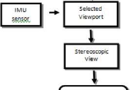
The authors of this study conducted the implementation and evaluation of the system through 360° camera, laptop and Android phone with built in gyroscope, accelerometer and magnetometer. The succeeding block diagram shows the flow of the concepts that constitute the proposed system in Figure 1.
The conceptual framework of the proposed system is presented in Figure 1. The block diagram shows the flow of the concepts that constitute in the system. The system starts with the capturing of live videos using RICOH THETA S, a 360° camera. This type of camera produces videos in dual fish eye format. The THETA UVC Blender, a driver provided by the RICOH Company, will stitch the output video into an equirectangular projection. Using the Internet, the PC connected to the 360° camera will transmit the live videos to the Android phone wirelessly. The Android phone is going to map the generated equirectangular video into a spherical model, thus, creating a 360° environment for the user. The user can navigate the environment through head movements using the gyroscope sensor of the phone. Stereogram SBS will be displayed into the phone to provide a realistic perception to the user.
360’ Camera
—L_
Equirecta ngular
Video ZTZ Real-time Video Mapping
I
Head Mounted
Display
Fig.1. The conceptual framework of the system.
-
A. Equirectangular Video
This section includes the process of capturing and transmitting live equirectangular video that is mapped in 3D model sphere that serves as the new spherical environment for the user. The live video is transmitted from computer to Android phone through Internet.
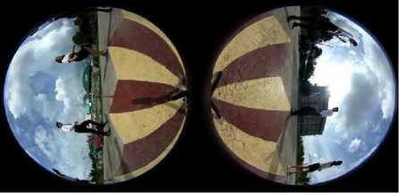
Fig.2. Dual fish-eye video format.
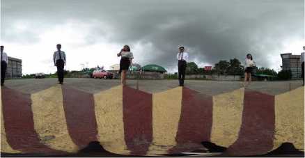
Fig.3. Equilectangular video format.
Ricoh Theta S has two fisheye lenses that is able to capture 180 degree Field-of-View and produce an output video in dual fish eye format (Figure 3) which was subject for image stitching by the THETA UVC Blender producing an equirectangular format (Figure 4). Ricoh Theta S connected to the PC with UVC Blender driver produces a live equirectangular preview as if it were used like a webcam. Since the generated video is in equirectangular projection, the client application mapped this into a 3D spherical model.
-
B. Real time video mapping
Equirectangular projection is a portion of the surface of a sphere projected into a flat images where the horizontal coordinate is simply longitude, and the vertical coordinate is simply latitude. The generated video is mapped this into a 3D spherical model. Figure 5 shows the projection of the 2D equirectangular video onto a 3D spherical model.
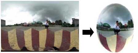
Fig.4. Equilectangular video format to Spherical video format.
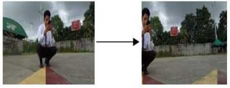
Fig.5. From reference point to right.
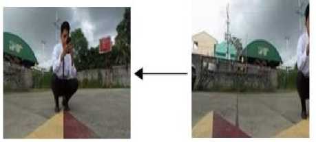
Fig.6. From reference point to left.
(x,y,z) = v = s in|. (3)
Where:
v = magnitude of x, y, and z coordinates
ϴ = angle rotation of quaternion
The value of v can be obtained by v = фх2 + у 2 + z 2 and the О can be found by rearranging the equation (3). With the given value of Ɵ and rearranging the equation (1), we can obtain the value of w which will be used in obtaining the Euler angles.
Euler angles provide a way to represent the 3D orientation of an object using a combination of three rotations about different axes. The conversion of Quaternion values to Euler angles can be done with the values of w, x, y, and z converted into yaw, pitch and roll movements. The Quaternion to Euler angles formula is:
Yaw:
As for the selected frame, the center of a certain image frame will be the reference point in which the user sees. Figures 5 and 6 illustrates how the views of a certain reference point change in relation with the user’s head movement. These figures also show that the system can project a continuous view in every direction or orientation, thus not rendering any black pixels. However, there are some specific parts of the spherical environment which is not perfectly stitched and produces a mismatch between the stitching of the two images captured by the Ricoh Theta S showed in Figure 7.
arcsin (2(cw + у z)). (4)
Pitch:
Roll:
arcsin
2 (w x +у z)
1 - 2 (x 2 + у 2 ) .
(
. - 2 (x 2 + z 2 ) .
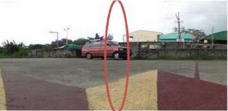
Fig.7. Sample of image mismatch due to improper stitching.
-
C. Selecting a viewport
Each IMU sensor outputs its orientation in quaternion form. All quaternions that represent a 3D rotation are represented by unit quaternions. Quaternions are extremely efficient at representing rotational and orientation information. The formula of quaternion is:
e , . e q = co s + vs in . ' 2 2
And can be presented as:
w =
e с о s-.
The resultant angles calculated will determine the orientation of the view from the 360 ̊ camera with respect to the head pose of the user.
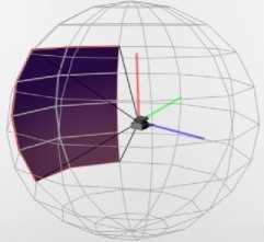
Fig.8. Visualization of viewport in spherical environment.
-
D. Producing a 3D video by applying Stereogram SBS
Stereogram SBS is the most common method used in Virtual Reality for achieving 3D perception where one of the views is intended for the left eye and the other for the right eye.
Figure 10 shows the Stereogram SBS of the viewport that is joined to create a depth from the disparity between two views. The generated SBS viewport has a disparity with a constant value of 5mm, 10 pixels/mm. The baseline refers to the pupillary distance of a person, it has a minimum and maximum distance of 51 mm and 77 mm, respectively. On the other hand, the focal length of the HMD has a range of 35 mm to 43 mm.
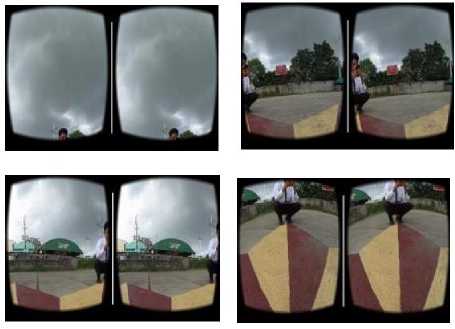
Fig.9. Stereoscopic view in different directions.
-
E. Geometry of Binocular Stereo
Figure 10 shows the geometry of binocular stereo, which mimics the operation of human eyes in perceiving depth.
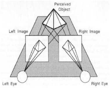
Fig.10. Human eyes in 3D perception.
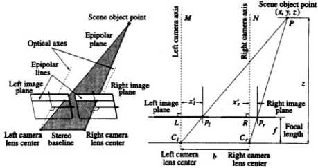
Fig.11. Geometry of Binocular Stereo.
From figure 11, two identical cameras in the x-axis are used to represent human eyes. It is separated by a baseline distance (b). Two separate images are created by the cameras, which results to a left image plane (Pl) and a right image plane (Pr). These two image planes are coplanar and are needed to produce a 3D image. Focal length, denoted as f, is the distance from the camera lens to the image plane created. While the distance between the image plane to the camera axis (M for the left camera axis and N for the right camera axis) is denoted as xl for the left image and xr for the right image. These two image plane will create a 3D image plane, denoted as P.
Using Figure 15, we can prove from the left camera that PMCL and PLLCL are similar triangles. We can state that:
X _ XL. Z~ f ;
Solving for x :
X = z^. (7)
Also, we can prove from the right camera that PNCR and PRRCR are similar triangles. We can state that:
X-Ь _ Xr. ;
Solving for x:
x = z RR + b. (8)
Equate (7) and (8):
z ^L ^z ^R +b;
z(S-X?) = b;
Where: z = depth
Xl = distance between the left camera to the left image plane in the x-plane
Xr = distance between the right image plane to the right camera in the x-plane
/ = focal length b = baseline
Disparity is the difference between xl and x r , and it can be solved by getting the distance from the image projected to the left eye to the image projected to the right eye. In Figure 3.8, it can be seen the disparity between the two views used in Stereogram SBS.
-
III. Data Gathered
-
A. Quaternion to Euler angle conversion
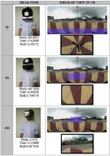
The field of view or also known as the angle of view projects at 90 ̊. A viewport is a 2D rectangle that defines the size of the rendering surface onto which a 3D scene is projected. The viewport choose a specific area from the sphere and that area will be streamed into the VR headset.
The output of the viewport is in rectangle and it is SBS for more realistic view. subjected in screen splitting or also known as stereogram
Table 1. Data gathered by the IMU sensor based on head movement
|
IMU SENSOR |
HEAD POSE |
||||||
|
X |
Y |
Z |
W |
PITCH |
YAW |
ROLL |
|
|
(i) |
-0.00 |
-0.03 |
0.04 |
0.99 |
-89.49 |
-5.42 |
-0.503 |
|
(ii) |
0.04 |
-0.36 |
0.03 |
0.97 |
-46.79 |
-4.44 |
3.709 |
|
(iii) |
0.05 |
-0.66 |
0.04 |
0.74 |
-5.98 |
-2.16 |
0.647 |
In relation with the IMU sensor data presented in Table 1 and Table 2 shows the viewport represent of the user’s head pose wearing the VR box and the view projected by the Android client. The table shows that there is a certain view in a certain direction, thus proving that there is a spherical environment created.
Table 2. Corresponding view projected in the VR headset in relation to the head orientation of the user
The following viewports selected from the 360° were processed into Stereoscopic view. Figure 13 shows Stereogram SBS of the viewport from the designated reference point generated.
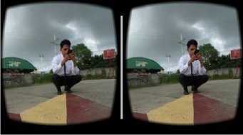
Fig.12. Stereoscopic view of the reference point.
The generated SBS viewport has a disparity with a constant value of 5mm, 10 pixels/mm. The baseline refers to the pupillary distance of a person, it has a minimum and maximum distance of 51 mm and 77 mm, respectively. On the other hand, the focal length of the HMD has a range of 35 mm to 43 mm. Table 1 presents the data gathered for evaluating the realism by Geometry of Binocular Stereo using the baseline and focal length.
Table 3. Data Gathered For Evaluating the Realism by Geometry of Binocular Stereo
|
BASELINE |
FOCAL LENGTH |
DEPTH |
BASELINE |
FOCAL LENGTH |
DEPTH |
|
51 |
35 |
35 |
68 |
39 |
53 |
|
51 |
36 |
36 |
68 |
40 |
54 |
|
51 |
37 |
37 |
68 |
41 |
55 |
|
51 |
38 |
38 |
68 |
42 |
57 |
|
51 |
39 |
39 |
68 |
43 |
58 |
|
51 |
40 |
40 |
76 |
35 |
53 |
|
51 |
41 |
41 |
76 |
36 |
54 |
|
51 |
42 |
42 |
76 |
37 |
56 |
|
51 |
43 |
43 |
76 |
38 |
57 |
|
59 |
35 |
41 |
76 |
39 |
59 |
|
59 |
36 |
42 |
76 |
40 |
60 |
|
59 |
37 |
43 |
76 |
41 |
62 |
|
59 |
38 |
44 |
76 |
42 |
63 |
|
59 |
39 |
46 |
76 |
43 |
65 |
|
59 |
40 |
47 |
77 |
35 |
53 |
|
59 |
41 |
48 |
77 |
36 |
55 |
|
59 |
42 |
49 |
77 |
37 |
56 |
|
59 |
43 |
50 |
77 |
38 |
58 |
|
68 |
35 |
47 |
77 |
39 |
60 |
|
68 |
36 |
48 |
77 |
40 |
61 |
|
68 |
37 |
50 |
77 |
41 |
63 |
|
68 |
38 |
51 |
77 |
42 |
64 |
-
IV. Conclusion
The researchers developed a system that is able to transmit a real-time realistic videos captured by the 360° camera into the Android phone mounted on the Virtual Reality box wirelessly. According to the gathered data from the system, the elimination of black pixels was accomplished by the stitching process of THETA UVC Blender used in the system. Furthermore, the 3D video was produced by the application of Stereogram SBS and also proved by using the Geometric Binocular Stereo. The researchers recommend to create or develop a video stitching process that can eliminate the mismatch part of the spherical environment created by the THETA UVC Blender. In addition to that, future research about this study may use a latest 360° Camera for a higher resolution to improve the quality of the live video. This modification can improve the 3D effect of the projected live video.
Acknowledgment
The completion of this undertaking could not have been possible without our relatives whose faith and prayers are within us all throughout the period of this study. They served as our inspiration and motivation to finish our study and make them proud.
To our close friends whose support and encouragement are never ending. Thank you for encouraging and believing in us.
And also to our adviser, Engr. Roselito E. Tolentino, for his endless support and supervision during our consultation up to our final demonstration and presentation. With his dedication and management, our study is made its way through the finish line.
And above all, we would like give our earnest gratefulness to our Almighty God for all the blessings and guidance He had given us, truly everything is possible with Him.
He had an on-the-job training at ON Semiconductor Philippines Inc. OJT Program and Philippine Long Distance Telephone Company – PLDT Inc. in 2016 and 2017 respectively. He is also a member of Institute of Electronics Engineer of the Philippines, Inc. Laguna and PUP-SRC Association of Electronics and Communications.

Marvin E. Legaspi was born on April 8, 1997 in San Pedro, Laguna. He is a graduate of BS in Electronics and Communications Engineering in Polytechnic University of the Philippines Santa Rosa Campus. He graduated Salutatorian in high school and 3rd Honourable Mention in elementary.
He had an on-the-job training at Newlong Industries Philippines Inc. and Philippine Long Distance Telephone
Company – PLDT Inc. in 2016 and 2017 respectively. He is also a member of Institute of Electronics Engineer of the Philippines, Inc. Laguna and PUP-SRC Association of Electronics and Communications.
References Real-time realistic telepresence using a 360° camera and a virtual reality box
- Bergeon, Y., Doskočil, R., et. al. Stereo Vision for Teleoperated Robot: Experiments and Results. Ministry of Defence of the Czech Republic.
- Ha, V., Nguyen, T., et. al. (2016) Real-time video streaming with multi-camera for a telepresence wheelchair. 2016 14th International Conference on Control, Automation, Robotics and Vision (ICARCV).
- Huang, J., Chen, Z., et. al. (2017). 6-DOF VR Videos with a Single 360-Camera. 2017 IEEE Virtual Reality (VR).
- Moon, B., Choi, J., et. al. (2017). Connecting Motion Control Mobile Robot and VR Content. 2017 14th International Conference on Ubiquitous Robots and Ambient Intelligence (URAI).
- Nguyen, M., Tran, H., et. al. (2017) Exploration of the 3D World on the Internet Using Commodity Virtual Reality Devices. Multimodal Technologies and Interact 2017.
- Pathak, S., Moro, M., et. al. (2016). A Decoupled Virtual Camera Using Spherical Optical Flow. Cross-ministerial Strategic Innovation Promotion Program (SIP), Infrastructure Maintenance, Renovation, and Management’, Council for Science Technology and Innovation.
- Ren, Y., and Fuchs, H. (2016). Faster Feedback for Remote Scene Viewing with Pan-Tilt Stereo Camera. IEEE Virtual Reality Conference 2016.
- Ricoh Imaging Company, LTD. (2016). RICOH Live Streaming Driver (THETA UVC Blender) with Equirectangular Output.
- Shanyuan Teng (2016). RICOH THETA 360 Video (From File) Unity Tutorial.
