Rectangular Microstrip Patch Antenna with Partial Ground, Slot, and Step for 5-6GHz IoT Applications

Author: Sonu Rana, Jyoti Verma, A.K. Gautam
Journal: International Journal of Wireless and Microwave Technologies @ijwmt
Article in issue: 6 Vol.12, 2022.
Free access
A wideband microstrip antenna is proposed with the partially ground structure for ISM (Industry, Science, Medical) band other wireless applications like worldwide interoperability for microwave access (WiMAX), and wireless local area network (WLAN). The need for compact antennas is continuously growing due to the rapid expansion of applications in today's environment. In this paper, a novel compact broadband patch antenna with an oval patch, rectangular slot, step, and partial ground is presented, which is compatible with ISM band, WLAN, and WiMAX applications. For S11(10dB) the suggested antenna has a bandwidth of 4.78GHz to 6.80GHz. The prototype is constructed on a commercially available FR4 substrate with dimensions of 20*15*1.6 mm3. The proposed antenna is ideally suited for ISM band WiMAX and WLAN applications. For bandwidth enhancement, a rectangular cut, a step below an oval patch is used and a partial ground structure is used to improve reflection co-efficient parameters (S11).
Wideband antenna, ISM band, WLAN/WiMAX applications, Partial ground structure
Short address: https://sciup.org/15019195
IDR: 15019195 | DOI: 10.5815/ijwmt.2022.06.04
Text of the scientific article Rectangular Microstrip Patch Antenna with Partial Ground, Slot, and Step for 5-6GHz IoT Applications
In the present era, modular designs, broadband, and reduced-size antennas that support numerous network applications simultaneously are in a growing market. Designers may be capable to use those same antennas to build communications connectivity. The IEEE 802.11b/g/5.15 GHz standard covers a range of frequencies from 2.4 to 2.484 GHz. The WiMAX spectrum spans 5.825 GHz (IEEE 802.11a) to 5.825 GHz (IEEE 802.11b) (IEEE 802.11b). These frequencies fall between 2.4 and 2.68 GHz/3.39 and 3.70 GHz/5.24 and 5.84 GHz range. The high-impedance microstrip antenna will be necessary for radiocommunication devices [1]. Due to their less cost, less weight, and better concert, microstrip antennas promise a better choice in modern wireless communication systems. Such antennas have typically inadequate in their pertinency due to their narrow bandwidth. These devices' impedance bandwidth (IBW) could be augmented by varying the shape of the radiating patch by etching slots and adding rectangular steps of varying sizes [2,7]. The recently shaped defective ground structure could be cast-off to supplement a solid ground plane in patch antennas to boost impedance bandwidth [8,9]. A defective ground plane has the benefit of minimizing the system's size and allowing the activation of additional resonance bands [10]. Because of the huge trend of wireless communications, hand-held devices now require low-profile, small, and wide-band antennas that can perform across many frequency groups, minimizing the need for distinct antennas for different applications. Microstrip patch antennas are in a momentous market for wireless infrastructures [11]. Future radiocommunication systems would necessitate structures with broad-band capability in highly changing environments [12]. For sustaining a wide range of necessities, including personal communication, home, vehicle, and workplace networking system. The radiocommunication market has prolonged intensely, and request for the ISM band, WLAN, and WiMAX is growing day by day. The receiver/Transmitter is a crucial constituent in performance, reliability, and size, it must meet three sets of requirements at the same time [13].
i) Dimensional appearances (compact size, lightweight, flexibility to official platform, and consumer); ii) Electronics efficiency (wide bandwidth, radiation qualities, high performance, design flexibility, and diversification applicability) iii) Production constraints (cheap price, reliability, packing competencies). The radio receiver’s performance must not be affected by the surrounding environment, such as the social body, and the proposal must gratify fallout security and safety requirements. Radiocommunication communications continue on the way to grow at a rapid rate in the domains of cellular phones, wireless Internet, and wireless home networking. The IEEE 802.1 1 communication standard is responsible for defining wireless system ethics, including wireless local area networks (WLAN, WiMAX) [14]. The most essential innovations are present in the ISM bands from 2.4–2.4945 GHz to 5.15– 5.936 GHz [15]. For example, WLANs that are currently the quickest and most reliable (for example, IEEE 802.11a [16]) operates in the 5–6 GHz frequency range, allowing for steady high-speed communication between all electronic gazettes like portable computers, personal organizers, and other wireless digital utilization [17]. In projected research, a diverse small broadband oval patch antenna is developed for 5 to 6 GHz ISM band, WLAN, and WiMAX applications. Because it can operate between 4.9 and 6.7 GHz, the suggested antenna is well-suited for the suggested solutions. The range of frequency for this antenna is 5.16–5.836 GHz, which covers the full ISM band. This micro-printed microstrip antenna is ideal for biomedical engineering and medical device installation.
2. Proposed Antenna Structure
The recommended antenna construction is demonstrated in Fig 1. The proposed antenna is designed by commercially available FR-4 substrate with relative permittivity of value 4.4. The dimensions of the base area are 20*15 mm2. The excitement started with 50 Ω thick microstrip feed with a length width and height of 8*1.5*1.6 mm3. An oval shape radiator patch and a rectangular step below the radiator are used in this study to enhance bandwidth and make the antenna appropriate for all 5-6 GHz applications by covering the entire spectrum. The estimated surface current distribution at various sampling frequencies of 5 - 6 GHz is represented in Fig .2. to validate broadband performance. The strong surface current occurs through both the oval-shaped and rectangular slots, as seen in Fig .2. (a). The first resonant mode of 5 GHz is seen to be produced by the oval shape and rectangular strip. The strong surface current is scattered over the oval patch, step, slot, and ground plane for the sampling frequency of 6 GHz, as illustrated in Fig 2(b, c).
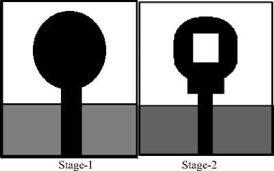
Fig. 1. Stages (Stage-1, 2) of the projected oval shape patch antenna
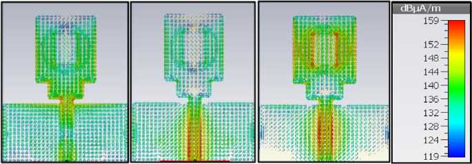
(a) 5 GHz (b) 5.5 GHz
(c) 6 GHz
Fig. 2. Current spreading at various frequencies (5, 5.5, 6 GHz) of the projected antenna design.
Table 1. Design specifications of projected antenna
|
Parameters |
Values in mm |
|
Fr-4 substrate with relative permittivity (ℇ) 4.4 |
15* 20* 1.6 |
|
Oval shape radiator patch |
7* 8 |
|
Rectangular slot on radiator patch |
3* 6 |
|
Rectangular step below radiator patch |
3*2 |
|
50 Ω microstrip feed fine |
1.5* 8 |
|
Partial ground plane |
15*7 |
|
Edge cut of radiator patch |
2 |
Fig.5. depicts an oval-slotted patch antenna's estimated return loss (S11). The bandwidth of the suggested antenna for return loss (S11) is 4.7 to 6.1 GHz with a high-frequency structure simulator and 4.91 to 6.61 GHz computer simulator technology (CST) studio suite 2018 version, which covers the whole 5-6 GHz range. The HFSS and CST results are very similar.
With the popular frequency range of 5-6 GHz, developed antenna gratifies the VSWR necessity of loss less than 2., as shown in Fig. 4. The impedance bandwidth (IBW) of planar monopole antennas is affected by multiple factors, along with the radiator element's size and the ground plane's size. This study focuses on the effects of the rectangular step's length and width and variations in length of partial ground plane. It may demonstrate using this broadband antenna's return loss(S11).
3. Effect on Variations of step length (L step) by Changing Parameters
The S11 parameter was simulated for various step lengths as shown in Fig.6. The lower-edge frequency remains unchanged as the step length increases, while the topmost frequency rises. The appropriate step length is L step=2mm.
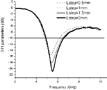
Fig. 6. Simulated results S 11 parameters for changed values of step length (L step)
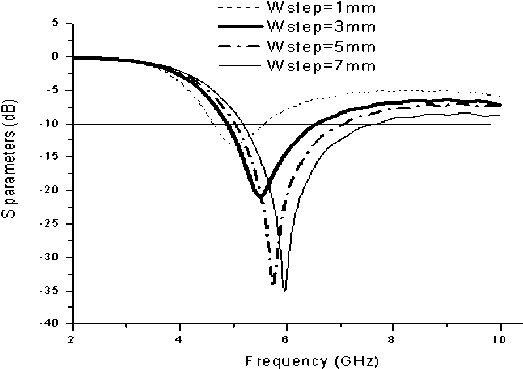
Fig. 7. Simulated results S 11 parameters for changed values of step width (W step)
4. Effects of Variations on Step width (W Step) by Changing Parameters
-
Fig.7. shows the S11 parameters for several step width values. The width of the rectangular step appears to significantly impact the bandwidth. Wstep=3mm is employed in this study to achieve a 5-6 GHz operational bandwidth.
-
4.1 Properties on variations of partial ground plane length (Lg) by changing parameters
-
4.2 The simulated Radiation pattern of the projected antenna
The difference in values of S11 parameters is function of partial ground plane scope could be seen in Fig. 8. As the partial ground plane length is increased, lower and upper frequencies would also shift on the way to right and bandwidth will also shift towards upper frequencies. The optimized partial ground plane length is set at 7mm using the ideal settings described overhead.
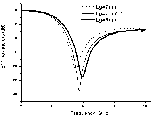
Fig. 8. Simulated S 11 parameters for the changed values of ground plane length
The replicated radiation patterns at 5.25, 5.55, and 5.85 GHz are plotted in Figs 9-11. The proposed antenna's radiation patterns are essentially omnidirectional over the operational bandwidth, analogous to a distinctive monopole antenna.
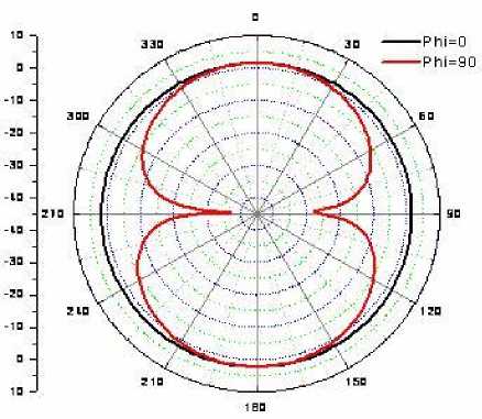
Fig.9. Radiation pattern of projected antenna at frequency 5.25 GHz
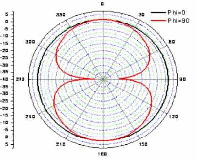
Fig. 10. Radiation pattern of projected antenna at frequency 5.55 GHz
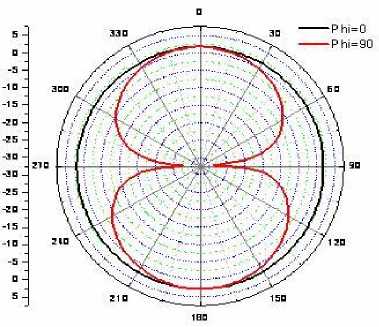
Fig. 11. Radiation pattern of projected antenna at frequency 5.85 GHz
The greatest improvement over the entire frequency range is represented in fig.12. Due to its high gain, the projected antenna design is well suited for 5 to 6 GHz ISM, WLAN, and WiMAX applications.
3.0
-
2.5 Ч
G-
А2.0 ■
I.
N1.5 J
(db),
1 .0■
0.5-0.0 --------------------------,--------------------------,--------------------------,--------------------------,,5.0 5.2 5.4 5.6 5.86.0
5. Conclusion
Frequency (GHz)
Fig. 12. The Gain of projected antenna in dB over frequency band 5-6 GHz
The characteristics of oval shape rectangular microstrip antenna impedance are enhanced by using a rectangular step and slot in the radiator patch element of the antenna. The results of the high-frequency structure simulator (HFSS) and computer simulation technology (CST) microwave studio experiments shown above are honestly equal. Due to its compact size and outstanding performance, the suggested rectangular slotted patch and step below the radiator could be a promising choice for widely used 5 to 6 GHz and broadband applications (ISM band, WLAN, WiMAX). The frequency range for VSWR 2 is between 4.8 and 6.5 GHz. Over its operational band, the antenna's emission pattern and maximum gain are detailed.
References Rectangular Microstrip Patch Antenna with Partial Ground, Slot, and Step for 5-6GHz IoT Applications
- Bao X, Ammann MJ. Dual-frequency dual-sense circularly-polarized slot antenna fed by microstrip line. IEEE Trans Antennas Propagation. 2008;56: 645-649.
- Saurav K, Sarkar D, Srivastava KV. Dual-polarized dual-band patch antenna loaded with modified mushroom unit cell. IEEE Antennas Wireless Propagation Lett. 2014; 13: 1357-1360.
- Thakur JP, Park J-S. An advanced design approach for circular polarization of the microstrip antenna with unbalance DGS feedlines. IEEE Antennas Wireless Propagation Lett. 2006; 5: 101-103.
- Wang C-J, Lin C-M. A CPW-fed open-slot antenna for multiple wireless communication systems. IEEE Antennas Wireless Propagation Lett. 2012;11: 620-623.
- Baek JG, Hwang KC. Triple-band unidirectional circularly polarized hexagonal slot antenna with multiple L-shaped slits. IEEE Trans Antennas Propagation. 2013; 61:4831-4835.
- Pan YM, Zheng SY, and Hu BJ, Wideband and low-profile omnidirectional circularly polarized patch antenna, IEEE Trans Antennas Propagation. 2014;62: 4347-4351.
- Gautam AK, Kunwar A, Kanaujia BK. Circularly polarized arrowhead-shaped slotted microstrip antenna. IEEE Antennas Wireless Propagation Lett. 2014; 13:471-474.
- Reddy VV, Sarma NVSN. Triband circularly polarized Koch fractal boundary microstrip antenna. IEEE Antennas Wireless Propagation Lett. 2014;13: 1057-1060.
- Reddy VV, Sarma NVSN. Compact circularly polarized asymmetrical fractal boundary microstrip antenna for wireless applications. IEEE Antennas Wireless Propagation Lett. 2014; 13: 118-121.
- Kunwar A, Gautam AK, Rambabu K. Design of a compact u-shaped slot triple-band antenna for WLAN /WiMAX applications. AEU Int J Electron Communication. 2017; 71:82-88.
- M. Ali, T. Sittironnarit, H.S. Hwang, R. A. Sadler, and G. J. Hayes, “Wide-Band/Dual-Band Packaged Antenna for 5–6 GHz WLAN Application,” IEEE Trans. Antennas Propagation., vol.52, N.2. pp. 610-615, February. 2004.
- J. L. Pan, S. S. Rappaport, and P. M. Djuric, “A multibeam medium access scheme for multiple services in wireless cellular communications,” in Proc. IEEE 1999 Int. Conf. Communication, vol. 3, 1999, pp. 1673– 1677.
- L. Jofre, B. A. Cetiner, and F. Flavius, “Miniature Multi-Element Antenna for Wireless Communications,” IEEE Trans. Antennas Propagation., vol.50, N. 5. pp. 658–669, May 2002.
- I-F. Chen, C. M. Peng, and S-C. Liang, “Single Layer Printed Monopole Antenna for Dual ISM Band The operation,” IEEE Trans. Antennas Propagation., vol.53, N. 4. pp. 1270–1273, April. 2005.
- R. Jordan and C.T. Abdallah, “Wireless communications and networking: An overview,” IEEE Antennas Propagation. Mag., vol. 44, pp. 185– 193, Feb. 2002.
- Available in: http://standards.ieee.org/catalog/olis/lanman.html.
- Y. Ge, K. P. Estelle, and T. S. Bird, “E-Shaped Patch Antennas for High-Speed Wireless Networks,” IEEE Trans. Antennas Propagation., vol.52, N. 12. pp. 3213–3219, December. 2004.
- Ansoft High-Frequency Structure Simulator corporation, V 9.2, 2004, http://www.ansoft.com/hfss
- Computer Simulation Technology: http://www.cst.com.
