Research on Modeling and Active Steering Control Algorithm for Electric Forklift Steer-by-Wire System

Author: Yang Liu, Benxian Xiao
Journal: International Journal of Intelligent Systems and Applications(IJISA) @ijisa
Article in issue: 11 vol.8, 2016.
Free access
In this paper, according to the structure char-acteristics of steer-by-wire (SBW) system for the TFC20 electric forklift, steering dynamics model and two degree of freedom vehicle model are deduced for SBW forklift. Aiming at the free design features of the angular trans-mission characteristics in the SBW system of electric forklift, the theory of active steering control strategy is studied. After analyzing the influence factors of the an-gular transmission ratio of the steering system, the ideal angular transmission ratio is proposed, which is based on the yaw rate gain invariance. Also, the control strategy of the yaw rate feedback and the full state feedback is stud-ied. The simulation results show that the above strategy is effective for the active steering control; it can improve the operating stability and the response speed of the fork-lift.
Electric forklift, full state feedback, ideal transmission ratio, modeling, steer-by-wire, yaw rate feedback
Short address: https://sciup.org/15010877
IDR: 15010877
Text of the scientific article Research on Modeling and Active Steering Control Algorithm for Electric Forklift Steer-by-Wire System
Published Online November 2016 in MECS
Along with the environmental protection has been the world’s attention and rapid development of logistics industry, electric forklift with less pollution, small noise and under the requirements of environmental protection and energy conservation, is widely used for stacking, handling and short distance transport of goods in warehouses, factories, ports and other places. Electric forklift is industrial vehicle that has more comprehensive application occasions, with a battery as power. Because of heavy cargo and narrow space, the requirements of steering characteristics and handling stability are higher than other vehicles.
The steering of front wheels in steer-by-wire (SBW) system is controlled by electrical signals; it has the function that the traditional steering system doesn’t have. A large number of papers and experimental studies show that the main characteristics of SBW system are improving the steering characteristics, improving the security and stability, improving the road sense and conducive to the integration control of forklift [1-10].
Remove mechanical linkage between the steering handle and front wheels is the main characteristic of SBW system, so the various limitations of conventional mechanical steering system are completely non-existent [8,9,11,12]. Therefore, the angular transmission characteristics of forklift can be easily designed, and the force transmission characteristics of the forklift can be designed according to the need of design, which brings infinite space to the design of the electric forklift steering characteristics.
Recently, a number of studies on the SBW control system have been carried out for the purpose of realizing perfect steering characteristics. In Ref. [2] and Ref. [3], a sliding mode control scheme for the SBW system with uncertain dynamic was used with the aim of enabling front wheels to closely follow the driver's command. In Ref. [4], in order to realize the handing stability, fuzzy control was applied for designing the nonlinear transmission ratio. In Ref. [5] a continuous time-varying tracking controller was designed for the vehicle's posi-tion/orientation using a simplified vehicle description and reference model for tracking. In Ref. [6], SBW system’s variable steering ratio was designed and front wheel angles were actively controlled by making desired yaw rate of front wheel SBW trace yaw rate of Four-Wheel-Steering whose steady slip angles are zero.
This paper first adopts the idea of the order reduction modeling, then the steering handle assembly module and the steering actuator module of SBW system are modeled. In order to simulate the system, the two degree of freedom vehicle model is established [2]. Second, the influence factors of active steering are analyzed. So the concept of the ideal transmission ratio is proposed, which adopts the variable transmission ratio that ensuring the yaw rate gain of electric forklift is not changed by the speed of vehicle and the steering angle. On this basis, the feedback control strategy of the state parameters of the forklift is studied. The simulation results show that the yaw rate and the full state feedback can effectively improve the operation stability.
This paper is organized as follow. In section II, the implemented SBW system is described, and the mathematical modeling of SBW is formulated, as well as the forklift steering motion state is defined. Section III illustrates the implementation of the control law in a SBW forklift as well as the test results. Finally, concluding remarks are presented in Section IV.
-
II. S BW S YSTEM M ODELING OF E LECTRIC F ORKLIFT
First, take the TFC20 forklift as an example to analyze its motion state. Then, the simplified models: steering dynamics model of SBW system and two degree of freedom vehicle model are established by means of the reasonable simplification.
-
A. The model of SBW system
-
1) The composition of SBW system
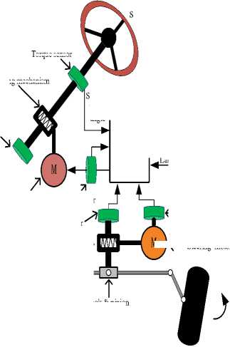
Generally, a complete SBW system of the TFC20 electric forklift contains electronic control unit (ECU), steering handle assembly and steering actuator [8,14]. The overall structure is shown in Fig. 1.
Steering wheel
Velocity
Yaw rate
Lateral acceleration
(- Current sensor
Angle sensor
Current sensor
Road wheel
Torque sensor
M
ECU
Vehicle sensors
Road feeling motor
Angle sensor
Reducing mechanism ->
Fig.1. Structure diagram of SBW system
Reducing mechanism
Steering wheel angle
M )<- Steering motor
-
2) The working principle of SBW system
When driver turns the steering wheel (i.e. the steering handle of forklift), the main controller ECU acquires angle, torque, vehicle states and other signals through sensors, then does logic analysis and calculation according the designed program. Steering motor drive signal can be worked out. Besides, the main controller (ECU) controls the road feeling motor to realize road feeling simulation of mechanical steering system [7-11].
-
B. Definition of forklift steering motion state
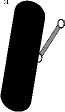
In the forklift steering coordinate system, the center of mass of vehicle ( O ) is defined as coordinate origin, the X-axis positive direction is defined as the advancement direction of vehicle which passes through the O in the horizontal plane, the Y-axis positive direction is parallel to the left side of driver passing through the O in the horizontal plane, and the Z-axis positive direction is vertical upward direction which is perpendicular to the horizontal plane passing through the O . There are four main physical quantities to describe the motion states of electric forklift. They are as follows: longitudinal velocity (u ) that the vehicle mass center along the X-axis speed; lateral velocity ( v ) that the vehicle mass center along the Y-axis speed; the yaw rate ( ω ), that is the angular velocity of the vehicle body around the Z-axis; sideslip angle ( β ) that the angle between the movement d irection of vehicle and the X-axis. Among them, the yaw rate and forklift's stability are most closely related in forklift stability control system. The yaw rate is the control variables that used to keep the lateral stability. Diagram of forklift coordinates is shown in Fig. 2.
Z
Yaw rate
Vertical velocity
Roll rate
Lateral velocity
<^| Lateral acceleration
Pitch rate Y
Fig.2. Diagram of forklift coordinates
When the sideslip angle of electric forklift is relatively small, forklift cornering ability is reflected by the yaw rate. When the forklift speed is certain, its turning radius becomes smaller as the yaw rate gets larger. In the same curve, if the forklift has a large yaw rate, it allows a higher speed.
The control ability of the driver to the lateral movement and the yaw rate of the forklift reduces when forklift sideslip angle increases. When driver can’t control the forklift will lead to the occurrence of accidents. Road adhesion coefficient and forklift sideslip angle have close relationship, when the road adhesion coefficient decreases, the forklift maximum allowable sideslip angle also decreases [8,9,12-14].
-
C. Steering dynamic model of SBW system
-
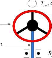
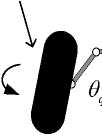
1) Dynamic model of the steering handle
Let J is the mo ment of inertia of the steering handle, J is the mo ment of inertia of the road feeling motor. The torque of the steering handle, the electromagnetic torque of the road feeling motor and the torque of the road feel motor torque applied to the steering column, are respectively , and . The viscous friction coeffi-sw , m1 d1
cient between the steering handle column and the bearing is .The viscous friction coefficient between the shaft sw of road feeling motor and the bearing is B . The steering angle of steering handle and the road feeling motor are respectively 5^ and -ml. The transmission ratio of the motor through the reduction gear to the steering column is G . Simplified physical model of the steering handle is shown in Fig. 3.
di, d0 ,
R i a 1 + L 1 -a 1 + k e 1 - -m 1 = U a , dt dt
Laplace Transform:
R 1 i a 1 ( s ) + L 1 i a 1 ( s ) s + ke 1 9 m1 ( s ) s = Ua 1 ( s )
Steering handle
Steering column
sw
J sw
Where U is the armature voltage of the road feeling motor, i is the armature current of the road feeling motor. The armature resistance, inductance and back-EMF coefficient of the motor are respectively R , L and k [15,16,17].
(4) Relationship between the electromagnetic torque and current of the road feeling motor:
Laplace Transform:
Road feeling motor
Reduction mechanism
J m 1 , T m 1, 9 m 1
B m 1
Fig.3. Simplified schematic diagram of steering handle module
(1) The steering handle module
The dynamic equation of the steering handle:
d 25
swsw sw s sw d 1
dt2
Laplace Transform:
T - JS (s)s2 - BS (s)s = Td 1(s)(2)
(2) The road feeling motor
According to the moment balance theory, the mechanical characteristic equation of the road feeling motor is obtained by the handle steering:
T -m 1
T d2 e m 1 m 1 dt 2
—
R d— 1 T d 1
B = m1 dt G
Laplace Transform:
T ( s )
Tm 1 - Jm 1 9 m 1 ( s ) s - Bm 1 q m 1 ( s ) s =
G 1
(3) The electric characteristic equation of the road feeling motor with DC motor:
T =k i m1 m 1 ‘a 1
T m 1 = k m 1 i a 1 ( s )
Where k is the electromagnetic torque constant of the road feeling motor.
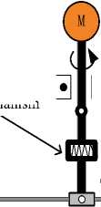
2) Dynamic model of the steering actuator
Rack-and-pinion steering structure is used in the SBW system. The equivalent moment of inertia of gear mechanism in steering system is J . The mo ment of inertia of the steering motor is J . The output torque and the electromagnetic torque of the steering motor are respective-ly T and T , the aligning torque of the front wheel steering is T . B and B are the friction coefficient that steering mechanism with the steering wheel equivalent to steering shaft and the steering motor shaft with its bearing. The angle of steering wheel equivalent to steering shaft and steering motor are respectively — and -m2 . The transmission ration of the steering motor through a reduction mechanism to the steering shaft is G . Simplify steering actuator model is shown in Fig. 4.
Reduction mechanism
Steering wheel
Steering motor
G 2
6 ,,J „Г , m 2, m 2, m 2
T
a
I* в, m 2
, J ,B ,T„
, q , q , R
Rack and pinion gear
Fig.4. Schematic diagram of the steering actuator
-
(1) The steering motor
The steering motor adopts DC motor and the mechanical equations are obtained according to the moment balance theory:
m2m2a m2 m2 m2 = dt2
Laplace Transform:
T ( s )
Tm2-Jm2θm2(s)s2-Bm2θm2(s)s= Ta(s)
G 2
-
(2) Electric characteristic equation of the steering motor:
R2ia2+L2dia2+ke2dθm2=Ua2
dtdt
Laplace Transform:
R2ia2(s)+L2ia2(s)s+ke2θm2(s)s =Ua2(s)
Where U is armature voltage of the steering motor, i is armature current of the steering motor. The armature resistance, inductance and back-EMF coefficient of steering motor are respectively R , L and k .
-
(3) Relationship between the electromagnetic torque and current of the steering motor:
T,=k,i,(13)
m2
Laplace Transform:
Tm2 =km2ia2(s)
Where k m is the electromagnetic torque constant of the steering motor.
-
(4) The front wheel and the steering motor actuator
Dynamic equation of the steering motor:
d 2 θ d θ T
T - J qqR a q dt 2 q dt r
Laplace Transform:
T a - J q θ q ( s ) s 2 - B q θ q ( s ) s = TR ( s ) (16)
r p
Where r is the torque amplification factor of the front wheel and the steering motor to the small gear, here simplified by a constant.
-
D. Two degree of freedom vehicle model
The establishment of whole vehicle model is a key step in the analysis of operation performance for forklift. In this paper, the steering control of TFC20 electric forklift is studied by using the two degree of freedom vehicle model.
Analysis of vehicle operation stability generally focuses on the three degrees of freedom, i.e., lateral, yaw and roll. A large number of papers have proved that the two degree of freedom model is more accurate in both qualitative and quantitative aspects [2-4,18]. A schematic diagram of the linear two degree of freedom model of the forklift steering movement is shown in Fig. 5.
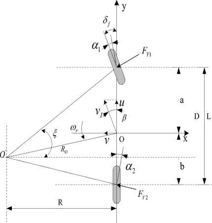
Fig.5. Linear two-degree-freedom model of the forklift
Forklift steering system takes front-wheel steering angle as input, yaw rate and sideslip angle as output. The equations of motion are as follows:
m ⋅ ay = FY 1 + FY 2 (17)
I ⋅ d ω r = F ⋅ a - F ⋅ b (18)
Z dt Y 1 Y 2
Where F is the cornering force of the front wheel, F is the cornering force of the rear wheel.
Among them:
ay=u⋅(+ωr)
dt
F =k ⋅α =k ⋅(β+a⋅ωr -δ)
u
F =k ⋅α=k ⋅(β-b⋅ωr)
u
After finishing the differential equations of motion are as follows:
|
в = k i+ k, в + ( aMbkL - О ч, - mu mu 2 |
-—6f mu f |
|
. ak - bk a2 k + b2 k ^ = 1---2 в + —1--- 2 4 rr IZ IZu |
- ak- 6 I Z f |
the yaw rate is the most important influence factor, it is the control variables to keep the lateral stability[4,6,19]. In this section, based on the ideal angular transmission ratio, we will develop the control strategy of the yaw rate feedback and the full state feedback.
The parameters of two degree of freedom model for the forklift steering movement are listed in Table 1.
Table 1. Parameters of Forklift Dynamics
|
Parameter |
Definition |
|
в |
Sideslip angle at the center of mass (rad) |
|
® r |
Yaw rate (rad/s) |
|
S f |
Front-wheel steering angle (rad) |
|
a |
Distance between front wheel axle and center of mass (m) |
|
b |
Distance between rear wheel axle and center of mass (m) |
|
u |
Vehicle longitudinal velocity (km/h) |
|
m |
Vehicle mass (kg) |
|
Iz |
Yaw moment of inertia (kg.m2) |
|
k 1 |
Cornering stiffness for the front-wheel (N/rad) |
|
k 2 |
Cornering stiffness for the rear-wheel (N/rad) |
Rewriting (22) into state space format, we have
Table 2. Basic Parameter for TFC20
|
Parameter |
Value |
|
m |
5000 |
|
a |
0.718 |
|
b |
1.182 |
|
I |
6924 |
|
k 1 |
- 78450 |
|
k 2 |
- 76550 |
|
u max |
15 |
|
S sw |
[ - 90,90 ] |
|
S f |
[ - 90,90 ] |
Where
в _ a 1
_ ® r _ _ a
a 2 P a 4 ' ^
+
b
. bi _
S f
-
A. The ideal angular transmission ratio of SBW
The reason that SBW system is superior to the traditional mechanical steering is the use of two DC motors to replace mechanical connecting parts, the method of improving the steering characteristic is applying the modern electronic control technology to design the force transmission ratio or the angular transmission ratio, so as to improve the operation stability of the forklift [4,20].
-
1) Parameter definitions
The transmission ratio of forklift steering system ( i ) is defined as follows:
i = 5 s W /Sf (24)
k + k2 ak - bk ai =-------- , a2 =-------2--1 , mu mu2
a
akY - bk2
3 I z
a 2 k + b 2 k2
, a 4 =-----:-------
Iu
Where S^ and Sf are the steering angle of the steering handle and steering wheel.
In the research of vehicle SBW, the main research is to study steering gain. One of steering gains refers to the ratio of yaw rate ( ^, ) and steering wheel angle ( 6f ), represented by G ^ r . Under steady-state conditions:
b, =- kL , b .- "A .
mu IZ
The basic parameters for TFC20 electric forklift are listed in Table 2.
G ^ = ^_ = u. 1
Sf 6 L 1 + Ku 2
III. R ESEARCH ON A CTIVE S TEERING C ONTROL A LGORITHM OF SBW
Forklift handing stability is an important evaluation index of forklift active safety, the main influence factors are four physical quantities, respectively, vehicle peed, yaw rate, lateral acceleration and sideslip angle. Among them,
Where K = m(— -—) (s2/m2 ) is stability coefficient, Lkk which is an important parameter of vehicle steady respond.
Another steering gain refers to the ratio of yaw rate (^ ) and steering handle angle (Ssw), by using the symbol G'" . It's an important steering characteristics of ve-sw hicle system. Under steady-state conditions:
G 5 = ^
8" O w
1 u 1
i' L ' 1 + Ku2
When the steering angular transmission ratio is constant, the transition speed is obtained based on (29). We have:
Through the comparison of two steering gains, it is easy to find that they are directly proportional and the proportional coefficient is the angular transmission ratio of the steering system ( i ). Then,
u
1 ± У1 - 4i min L K s K 2 i min LK s K
= 0.44 m / s
G ^ r i = ——
G 5
sw
Then,
f t
( u ^ u 0 )
uL
The steering sensitivity is defined as follows:
K s = 5 (28)
O sw
K ─ Steady state gain of yaw rate.
2) To determine the ideal angular transmission ratio
During the running process of vehicle, ensuring vehicle’s steering gain is certain in different vehicle speeds and different steering handle angles. This kind of forklift has good maneuvering performance, don’t need driver additionally compensate yaw rate variation, which generated by vehicle speed. This method also can effectively improve the safety and stability of the vehicle at high speed.
Definition: angular transmission ratio under the condition of steady gain of yaw rate, which is defined as the ideal angular transmission ratio [4].
In SBW system, it should design a rational steering transmission ratio ( i ) to guarantee K is a constant. Assumed at any speed and steering handle angle, let the gain of yaw rate ( G ^ = 5 r /8^ = Ks ) is a constant, then determine the ideal angular transmission ratio ( i ):
i =
imin uL
ma b
[1 + 72 (p - Г) u 2 ] K s
L k 2 k 1
( u ^ u 0 )
( u > u 0 )
There is no standard method for choosing the gain value of yaw rate. Through the experimental research and statistics of modern cars, the car's steering sensitivity is 0.16-0.33 s - 1. The 0.23 s - 1 as the scale of the steering sensitivity, which can satisfy the one-to-one corresponding relationship between the steering handle angle and the steering wheel angle, thus determines the ideal angular transmission ratio.
The maximum steering angle of TFC20 electric forklift is 90 when forklift at low speed, and the limit value of steering wheel angle also is 90 , so the minimum value of steering angular transmission ratio is obtained as follows:
i min
0 sw max
0 f max
90 = 1
ma b
[1 + z2 (F-F) u ] K s
( u > u 0 )
Through the above method, the changing curve of ideal angular transmission ratio versus vehicle speed is shown in Fig. 6.
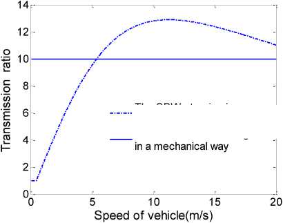
The SBW steering in a fixed steering sensitivity The front wheel steering
Fig.6. Curve of ideal transmission ratio versus speed of vehicle
The value of angular transmission ratio is small when forklift is driving at low speed, so the driver turning a small steering handle angle can have a greater steering wheel angle, which can reduces the burden of driver. In the high speed driving, the value of angular transmission ratio is larger, so the driver can avoid the fault operation under limit working conditions of forklift. It is advantageous to improve the safety and stability of forklift.
B. Active steering control strategy
Before discussing the active steering control strategy of SBW system, we need to emphasize the key features of active steering technology, and its greatest feature is able to adjust the operation stability during the process in real-time, to meet the requirements of different working conditions.
Firstly, characteristics of open-loop system are introduced, and then system characteristics of the full state feedback control system based on cornering stiffness and the yaw rate feedback are studied.
The evaluation indices of the open-loop system include (at zero initial conditions) response time, transition time, overshoot, natural frequency and so on [21-24]. Equation (32) is the transfer function of yaw rate relative to steering wheel angle.
” - ( s ) =G T » r s + 1
6 ( s ) ” ' Ts 2 + Ts + 1
According to (32), the following parameters are used to characterize the response quality.
-
(1) Yaw rate relative damping coefficient ( £ ):
5 = Ф VT
-
(2) Undamped natural frequency of yaw rate ( ” ):
As can be seen from the above equation, the input matrix of system is not affected by yaw rate feedback, but the control matrix can be changed. By yaw rate feedback, the transfer function of system is as follows:
” ( s ) b2s - ab 2 + a3b
6 ( s ) s 2 + [ b2F - ( a + a 4)] s + a ^4 - a2a 3 + F ( a3b - axb )
After (36) is written in form of (32), the expression of each coefficient is as follows:
” o 1/ TP
-
(3) Transition time ( T ): Te = 2 T/T
-
(4) Response time ( Tf ): T = T 2/ T ^
Substituting the above parameters into (32), we have:
G ”
a3b - axb2
axa4 - a2a 3 + F ( a3b - axb2 )
T = b2F - ( a 1 + a 4 )
-
1 axa4 - a2a 3 + F ( a3b - axb2 )
” ( s ) =G T - s + 1
8 f ( s ) = ” -U + 2^+1
s I s I
” o ” o
It’s not hard to see from the above equation, reducing the relative damping coefficient ( £ ), the system will increase the vibration tendency. Increasing the undamped natural frequency, the relative recovery capability of system will be greater.
-
1) Yaw rate feedback control
Fig. 7 is the yaw rate feedback control schematic. The correction of steering wheel angle is realized by the feedback of controller through the state variable (i.e., the yaw rate of the forklift). The actual steering wheel angle is (34).
J f = 5 f - F ” r (34)
Where J‘ is the target value of steering wheel angle, 6f is the feedforward steering wheel angle and F is the yaw rate feedback coefficient.
T =
T 2
axa4 - a2a 3 + F ( a3b - axb2 )
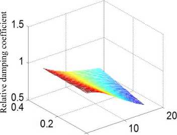
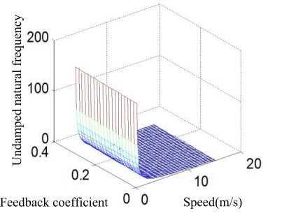
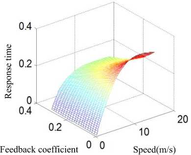
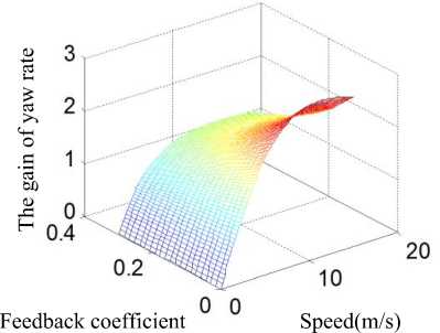
Based on MATLAB and the actual TFC20 electric forklift, the simulation experiment of yaw rate feedback control is carried out. The range of feedback coefficient ( F ) is 0~0.3. From the parameters of ^ , ” , Tf to investigate the effect of yaw rate feedback control on the performance of SBW system. Fig.8 shows simulation results.
0 0
Feedback coefficient Speed(m/s)
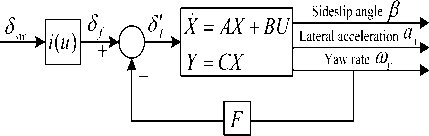
Fig.7. Control diagram of Yaw rate feedback
Substituting (34) into the two degrees of freedom state equation (23), we get the state space equation of system through yaw rate feedback.
P _ a1 . ”r J L a
a 2 - bF a 4 - b2F
в
. ”-
+
b 1
. b 2 .
(a)
(b)
(c)
(d)
Fig.8. Simulation results of yaw rate feedback response quality
control strategy can control the yaw rate and sideslip angle at the same time, to ensure active safety and handling stability of forklift.
We discuss the effect of steering characteristics due to the change of front wheel cornering stiffness, definition of virtual front wheel cornering stiffness is as follows:
k = k 1 (1 + 7 ) (37)
Where kx is virtual cornering stiffness and 7 is the cornering stiffness variation coefficient.
The steering wheel angle of the full state feedback is given by:
S f = kd5f - ( U + k pP ) (38)
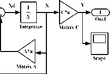
Where kd (kd = 1 + 7 ) is gain coefficient of steering wheel angle, kr ( kr = a7 ) is feedback coefficient of u yaw rate and kp (kp = 7 ) is feedback coefficient of sideslip angle. The simulation model of the state feedback system is shown in Fig. 9, and the full state feedback system is as follow:
x = Ax + B^f = (A - BK)x + B(1 + 7)^ _ y = Cx
From the figure (a) it can be seen that the relative damping coefficient ( £ ) increases with the increase of the feedback coefficient ( F ) and the relative damping coefficient decreases with the increase of speed under the same feedback coefficient. From the figure (b) we can see that the undamped natural frequency ( ^ ) increases as the feedback coefficient ( F ) increases, but it changes in small ranges and it decreases as the speed increases under the same feedback coefficient, which is particularly evident in the low speed range. With the increase of the feedback coefficient ( F ), the response time ( T ) doesn’t change significantly in the figure (c). Under the same feedback coefficient, the relationship between response time and speed can be seen as an approximate linear. From the figure (d) it can be seen that the gain of yaw rate on steering wheel angle is similar to the change trend of response time, however, when the feedback coefficient is large, the steering gain is basically invariable at high speed.
Summing up the above, yaw rate feedback can increase system bandwidth, make system more stable, shorten response time, speed up to the steady state value, but the sideslip angle still is out of control.
-
2) The full state feedback control based on cornering stiffness
The pole assignment and steering characteristics of system are changed by adding state feedback to the steering wheel angle, improving the operating stability of system. Full state (yaw rate and sideslip angle) feedback
Where k + k2 akx - bk mumu akx - bk, a2 k + b2 k2
IIu k1
mu ak
C = 1 0 , K =E k e kr 1 .
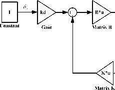
Fig.9. Simulation model of the full state feedback control system
According to the above analysis, a simulation model is built in MATLAB/Simulink. The simulation speed is 4m/s. Fig.10 and Fig.11 show the results of simulation carried out by setting the reference parameters as follow and using sinusoidal signal as input.
/

- 5
--n =0
n =0.2
n =-0.2
-10L
2 3 4 5 6 7 8 9 10
Time(s)
Fig.10. Actual steering angle input
Fig.11. Yaw rate response of different lateral stiffness
Fig. 10 illustrates the actual angle of steering wheel with the full state feedback is directly proportional to the cornering stiffness. Fig. 11 shows that the response of yaw rate increases in the full state feedback with the increase of the cornering stiffness, and it can also get a more sensitive forklift steering. On the contrary, the corresponding yaw rate will be reduced as the cornering stiffness decreases, and we can get a lower sensitivity of forklift steering.
-
IV. C ONCLUSION
Steer-by-wire system is an application in the field of vehicle power steering system; it is the hotspot and advanced technology in the field of steering technology. Its main feature is removing mechanical linkage between the steering wheel and front-wheels; it can realize the desired steering target by electronic controlling system. SBW can get rid of the limitation of conventional steering system. The advantage of the system is the independence of steering wheel and front-wheels, so it is possible to design the angular transmission and force transmission characteristic, the more design flexible, the more perfect steering characteristic. SBW is significant reformation in development of steering system.
This paper aimed at structural characteristics of TFC20 electric forklift steering system, and then deduced the steering dynamics model and the two degree of freedom vehicle model.
After analyzing the influence factors of the angular transmission ratio of steering system, the ideal angular transmission ratio based on steady gain of yaw rate is used to study the control strategy of the yaw rate feedback and the full state feedback. The simulation results show that the method improved the steering characteristic and respond time, ensured steering stability.
A CKNOWLEDGMENT
We would like to thank the editor and the reviews for their consideration. This work was supported by National Natural Science Foundation of China (61304007).
References Research on Modeling and Active Steering Control Algorithm for Electric Forklift Steer-by-Wire System
- Halton M., Hayes M.J. and Iordanov P, “State-space μ analysis for an experimental drive-by-wire vehicle,” In-ternational Journal of Robust and Nonlinear Control, Vol.18, No.9, pp. 975-992 ,2008.
- H. Wang, H. Kong, Z. Man, M. T. Do, Z. Cao, and W. Shen, “Sliding mode control for Steer-by-Wire systems with AC motors in road vehicles,” IEEE Transactions on Industrial Electronics, Vol.61, No.3, pp. 1596-1611, 2014.
- M. T. Do, Z. Man, C. Zhang, H. Wang, and F. Tay, “Ro-bust sliding mode learning control for Steer-by-Wire sys-tems,” IEEE Transactions on Vehicular Technology, Vol. 63, No. 2, pp. 580-590, 2014.
- Xiao, Benxian. “The Research of Fuzzy Variable Transmission Ratio for Steer-by-wire System of Electric Forklift.” International Journal of Intelligent Systems and Applications, Vol. 7, No.5, pp.31-39, 2015.
- Pradeep Setlur, John R. Wagner, Darren M. Dawson and David Braganza, “A Trajectory Tracking Steer-by-Wire Control System for Ground Vehicles,” IEEE Transactions on Vehicular Technology, Vol.55, No.1, pp. 76-85, 2006.
- Yu Leiyan, LinIN Yi and Shi Guobiao, “Research on active steering control strategy of steer-by-wire system,” Computer Simulation, Vol.25, No.5, pp. 233-235, 2008.
- Howser Gerry and McMillin Bruce, “Modeling and rea-soning about the security of drive-by-wire automobile systems,” International Journal of Critical Infrastructure Protection, Vol.5, No.3, pp. 127-134 ,2012.
- Masaya S., Shiro N., Osamu N., et al. “Vehicle stability control strategy for steer-by-wire system,” JSAE Review, Vol.22, No.9, pp. 383-388, 2001.
- P. Lemerle, O. Höppner and J. Rebelle, “Dynamic stability of forklift trucks in cornering situations: parametrical analysis using a driving simulator,” Vehicle System Dynamics, pp. 4910, 2011.
- Sven Kleine and Johannes Van Niekerk, “Modeling and Control of a Steer-By-Wire Vehicle,” Vehicle system dy-namics Supplement, Vol.29, No.28, pp. 114-142, 1998.
- Shu-fang G, Li-fang W, “Strategies to improve steering handling performance for steer-by-wire system,” Computer and Communication Technologies in Agriculture Engineering (CCTAE), 2010 International Conference On. IEEE, Vol.1, pp. 296-299, 2010.
- Yan He and Benxian Xiao, “Research of the forklift pow-er-assisted steering system based on safety steering speed control,” International Journal on Smart Sensing and In-telligent Systems, Vol.8, No.1, pp. 749-765, 2015.
- Chen Xiang, Yang Tiebao and Chen Xiaoqun, etc. “A generic model-based advanced control of electric pow-er-assisted steering systems,” IEEE Transactions on Con-trol Systems Technology, Vol.16, No.6, pp. 1289-1300, 2008.
- Rinchi Mirko, Pugi Luca, Bartolini Fabio and Gozzi Luigi, “Design of control system to prevent forklift capsize,” In-ternational Journal of Vehicle Systems Modeling and Testing, Vol.5, No.1, pp. 35-58, 2010.
- Mahfouz, Ahmad A., M. K. Mohammed, and Farhan A. Salem. "Modeling, Simulation and Dynamics Analysis Issues of Electric Motor, for Mechatronics Applications, Using Different Approaches and Verification by MATLAB/Simulink." International Journal of Intelligent Systems and Applications, Vol.5, No.5, pp. 39-57, 2013.
- Tao Meng and Hui Chen, "A Study on the Control Strategy for Wheel Return and Active Damping of Electric Power Steering System," Automotive Engineering, Vol.28, No.12, pp. 1125-1128, 2006.
- Pastorino, Roland, et al. "Geared PM coreless motor mod-elling for driver’s force feedback in steer-by-wire systems." Mechatronics, Vol.21, No.6, pp. 1043-1054, 2011.
- Zheng, Bing, and S. Anwar. "Yaw stability control of a steer-by-wire equipped vehicle via active front wheel steering." Mechatronics, Vol.19, No.6, pp. 799-804, 2009.
- Yan Peng, Wenqing Guo, Mei Liu, and Shaorong Xie, “Active modeling based yaw control of unmanned ro-torcraft”, International Journal on Smart Sensing and In-telligent Systems, Vol. 7, No. 1, pp. 380-399 ,2014.
- Baslamisli S.C., Polat I. and Kose I.E, “Gain Scheduled Active Steering Control Based on a Parametric Bicycle Model,” IEEE Intelligent Vehicles Symposium, pp. 1168-1173, 2007.
- Shen Huan, Tan Yunsheng and Mao Jianguo, “A driver model for dynamic evaluation of the EPS assistant char-acteristics,” Journal of Applied Sciences, Vol. 13, No.9, pp. 1455-1460, 2013.
- Alessandro Dell’Amico and Petter Krus ,“Modeling, Sim-ulation, and Experimental Investigation of an Electrohy-draulic Closed-Center Power Steering System,” IEEE/ASME Transactions on Mechatronics, Vol.20, No.5, pp. 2452-2462, 2015.
- Chitu Cristian, Lackner Jochen and Horn Martin, etc. “Controller design for an electric power steering system based on LQR techniques,” The International Journal for Computation and Mathematics in Electrical and Electronic Engineering, Vol.32, No.3, pp. 763-775, 2013.
- Zhen Zhang, K. T. Chau and Zheng Wang, “Analysis and Stabilization of Chaos in the Electric-Vehicle Steering System,” IEEE Transactions on Vehicular Technology, Vol.62, No.1, pp. 118-126, 2013.
