Research on the time synchronization technology based on the GEO Positioning System

Author: Jing wenfang, Lu xiaochun, Wang Jin, Wang Danni
Journal: International Journal of Information Technology and Computer Science(IJITCS) @ijitcs
Article in issue: 4 Vol. 3, 2011.
Free access
The method of common-view is characterized by higher precision, good convenience in use, and cheap instrument. A new time synchronous method for multiple users system by common-view technology is presented based on the GEO Positioning System (GEOPS). And the GEOPS common-view theory is studied for which is different from the other GNSS system. This paper introduces the working process and the time service pattern of the GEOPS. In the GEOPS, the pseudo-range found by the receiver through testing is actually the measurement of the whole link from the main control station and through the satellite to the receiver. Due to the different distances between the main control station and each satellite, this measurement has to be done using the upload delay correction by the main control station. The upload delay adopts a polynomial model and the polynomial parameters are demodulated from the navigation message to calculate the delay correction value during the adjustment. In accordance with these characteristics of GEOPS, we propose the GEOPS common-view theory. The format parameters of GEOPS common-view and data calculating method are presented. The time synchronization system, the error analysis and the applied plan of GEOPS common-view technology are introduced
GEOPS, multipel users system, time synchronization, common-view
Short address: https://sciup.org/15011631
IDR: 15011631
Text of the scientific article Research on the time synchronization technology based on the GEO Positioning System
With the development of science and technology, time and frequency is playing an important role in many fields, more and more fields need time and frequency synchronization. At present, the prevalent time methods are common-view based satellite, Two-way Satellite Time and Frequency Transfer (TWSTFT), carrying clock method, etc. By TWSTFT, the synchronization accuracy is high, but all the station including users must equip transmitter and receiver which enhance costs. By carrying clock method, time synchronization can be achieved, but it is difficult to fulfill remote regularly.
Common-view is a good choice for remote precise time and frequency transfer. Since its introduction in the early 1980’s, the single-channel GPS C/A code common-view receiver has been used by the international timing community to achieve precise time and frequency comparisons of remote atomic frequency standards[1]. The method of common-view is characterized by higher precision, good convenience in use, and cheap instrument, therefore the study on the application of common-view is very important. [1,2].
Common-view techniques have been used extensively in the GPS community and GLONASS community for over 20 years. Many paper introduce the technology based on GPS and GLONASS. In 2002, a group of Chinese astronomers at the Chinese Academy of Sciences presented a new concept, i.e., the GEO Positioning System (GEOPS). GEOPS is a positioning system based on satellite communication that is fundamentally different from the GPS, GLONASS and GALILEO [2]. In this paper, we introduce the principle of the GEO Positioning System (GEOPS) based on communication satellites, and also study the technology of time synchronization of multiple users system based on GEOPS.
-
II. The principle of GEOPS based on transmitting
SATELLITE
GEOPS is a satellite navigation system with the function of positioning, velocity measurement and time services. GEOPS is a positioning system based on communication satellite that is fundamentally different from the GPS, GLONASS and GALILEO systems. The latter use specialpurpose navigation satellites to broadcast navigation information generated on-board to users, while the GEOPS transfers ground-generated navigation information to users via the communication satellite. It used operational Geosynchronous Earth Orbit (GEO) communication satellites as navigation satellites whose locations are accurately measured. In this system, a virtual satellite clock technique is adopted to implement time synchronization between the satellite and the ground navigation station. An air pressure altimeter is used to supply navigation constellation and single frequency compensation technology is employed to measure Doppler frequency. The user can fulfill pseudorange measurement
Supported by 973 project ( Grant No.2007CB815502 ) , West Light Foundation of Chinese Academy of Sciences(Y001YR4701), and the National Natural Science Foundation of China (Grant No. 11073022),
requirements, and receiver positioning, navigation and timing services using more than three satellites[3].
The GEOPS system may be considered as comprising three segments: the control segment, the space segment, and the user segment. The GEOPS concept diagram is shown in Figure 1.
The control segment consists of five ground stations, including a master control station. These control stations are widely separated in longitude around the china. The master control station is located at ShaanXi . The main purpose of the control stations is to generate and upload the signal to the satellites. The signal includes system time, ephemeris, satellite transmitting time, satellite signal carrier and uplink signal. The master station also collects barometric data from the weather stations all over China. After processing the barometric data is broadcasted to users in GEOPS navigation message for altitude calculation.
The space segment consists of four geosynchronous orbit (GEO) communication satellites. If GEO communication satellites do not control along the north-south direction, they can provide the proper geometry of the constellation for navigation users.
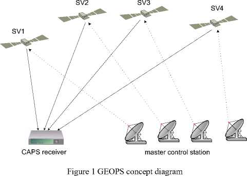
The user segment is the GEOPS receiver, which performs precise positioning, timing services and velocity measurement by receiving the C/A code and P code transmitted by the satellites, is the key component in the process of GEOPS design and testing.
The GEOPS system has some advantages compared with the traditional GNSS systems. Because the GEOPS system uses satellite transponders to transmit signals of the atomic clock and navigating messages from the ground station, the period and the investment of the whole system construction may be largely reduced. Meanwhile, signal system and satellite ephemeris structures can be revised freely according to requirement. Because time signals required for navigation system are offered by atomic clocks at the ground station, no satellite atomic clock is needed any more. At the ground station, the easy keep of the atomic clocks brings about very high accuracy and stability. It is helpful to decrease the technical requirements and improve the precision of navigation and positioning.
-
III. The method of Common-view based on GEOPS
-
A. Satellite virtual atomic clock
GEOPS is different with GPS and GLONASS. Without using the satellite atomic clocks, GEOPS adopts GEO communications satellites as the principal parts of the navigation satellites. The payload of the communications satellites transmits the navigation signals emitted from the ground. The propagation path of GEOPS signal is shown in Figure 2.
The basic pseudorange observation equation of GEOPS is:
ρ = c ( t u - t A ) (1)
Where ρ is the pseudorange from the user to the master control station, t u is the local time at which the receiver receives the signals, t A is the GEOPS system time at which the signals are transmitted from the master control station, and c is the speed of light.
This point is different with GPS and GLONASS. The basic pseudorange observation equation of GPS is:
ρ ′ = c ( t u - t s ) (2)
Where ρ ′ is the pseudorange from the user to the satellite, and t s is the system time at which the signals are transmitted from the satellite atomic clocks.
The master clock of GEOPS and the integrated baseband and are kept in synchronization[4]. The ranging code and the navigation message are modulated into carrier waves of intermediate frequency. The intermediate frequency is up-converter to 6GHz, and is transmitted to the satellite through the radio frequency channel. The navigation message includes satellite ephemeris parameters, ionosphere correction parameters, frequency revision parameters and time tracing measurement parameters. The GEOPS uplink RF signal travels through the atmosphere before reaching the satellite transporter. The GEOPS uplink RF signal is down-converter to 4GHz by the satellite transporter, and broadcast them to the users. Some delay errors may be considered.
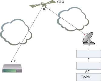
Figure 2 The propagation path of GEOPS signal
In GEOPS receiver, the normal pseudorange observation equation is the same as (2). The relation between t s and t A is:
t B = t A + Δ τ AB (3)
Where Δ τ AB is the signal propagation delay from the master clock to the satellite.
According to (2) and (3), ρ ′ can be expressed by
ρ'=c(tu -tB)=c(tu -tA -ΔτAB)=ρ-c⋅ΔτAB
In order to measure Δ τ AB exactly, GEOPS adopts the technology which is called “Satellite virtual atomic clock”. There is a delay between the time when the navigation signals are transmitted from the satellite and the time when the navigation signals are transmitted from the upload station on the ground. This delay varies with the radial distance of the satellite to the navigation upload station. The atomic clocks on the ground are used as a reference. The generation time of the navigation signals on the ground is then delayed into the transmitting time at the antenna phase center of the satellite. All the functions of GPS are achieved with no atomic clocks on the satellite. According to its actual measurement value and parameters of the model in the navigation message, we can get the virtual clock time modification Δ τ AB . If we can get the Δ τ AB very exactly, GEOPS is no different with other GNSS system. Here, by common-view techniques, the Δ τ AB common used in each user is canceled off.
-
B. Mutipul users time synchronization based on
GEOPS
According to common-view work principle, this technique allows the direct comparison of two clocks at remote locations. Here are multiple clocks to compare at remote locations. In this technique, e.g. three stations, C, D and E, receive a one-way signal simultaneously from a CAPS satellite and measure the time difference between this received signal and their own local clock. The time difference between each two clocks is determined by simultaneous observation of a third clock on a CAPS satellite. The data are then gathered into data processing center such as a computer. The concept diagram of multiple users time synchronization based on GEOPS is shown in Figure 3.
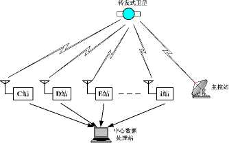
Figure 3 The multiple users time synchronization concept diagram
Station C, D and E receive time signal t A ( CAPS ) from the master control station which is transmitted by GEOPS satellite k simultaneously. Let the reception times of stations be t C , t D and t E . The time difference between each station and the master control station is expressed as follows.
Δ t CA = t C - t A ( CAPS )
= ΔτBC + ΔτAB = ΔτurC + ΔτufC + Δτtrop(BC) + Δτion(BC) + cBC + ΔτcA + ΔτAB
ΔtDA = tD - tA(CAPS) = ΔτBD + ΔτAB = ΔτurD + ΔτufD
ΔtEA = tE - tA(CAPS) = ΔτBE + ΔτAB = ΔτurE + ΔτufE
In formula(5), ΔtCA is the time difference between master control station transmitting time and the station C receiving time, tA(CAPS) is the system time at which the signals are transmitted from the satellite, Δτion(BC) is the ionosphere delay of BC space path, Δτtrop(BC) is the ρBC troposphere delay of BC space path, BC is the signal
ΔtCA - ΔtDA = tC - tD = (ΔτurC + ΔτufC) - (ΔτurD
+ Δ τ trop ( BD ) + Δ τ ion ( BD ) + c + Δ τ dA + Δ τ AB (6)
+ Δ τ trop ( BE ) + Δ τ ion ( BE ) + c + Δ τ eA + Δ τ AB (7) propagation delay from the master clock to the satellite, and Δ τ cA is the clock difference between master control station clock and station C clock. Inferring from this, we can know other symbols meaning about formula (6) and (7).
By calculating the difference between each two formulas among formula (5), (6) and (7), the time difference between each two stations can be deduced as follows.
+ Δ τ ufD ) + ( Δ τ trop ( BC ) - Δ τ trop ( BD ) )
+ (Δτion(BC) - Δτion(BD)) + ρBC c ρBD + (ΔτcA - ΔτdA)
Δ t CA - Δ t EA = t C - t E = ( Δ τ urC + Δ τ ufC ) - ( Δ τ urE + Δ τ ufE ) + ( Δ τ trop ( BC ) - Δ τ trop ( BE ) )
+ ( Δ τ ion ( BC ) -Δ τ ion ( BE ) ) + ρ BC c ρ BE + ( Δ τ cA -Δ τ e A ) (9)
Atni—Atcl =tn—tr =(Ат п+Ат,п) — (Ат r-+ At + (At, ,вп,—Ат, ,ВГЛ
DA EA D E urD ufD urE ufE trop ( BD ) trop ( BE )
+ ( Δ τ ion ( BD ) - Δ τ ion ( BE ) ) + BD c BE + ( Δ τ d A - Δ τ e A ) (10)
Where the delay arisen by the receivers’ baseband and radio processing part can be tested by real-time subsidiary observation such as ΔτurC、ΔτurD、ΔτurE and Δτ 、Δτ 、Δτ ufC ufD ufE . For the transferring signal is from the same master control station and the transferring frequency is almost the same, the ionosphere and troposphere delay from satellite to each user’s receiver can be counted same and canceled out. And for the time difference between each receiver station and the master control station is correlative to the master control station time, we define the sum of the i station clock time and the clock difference between i station and master control station is the clock time of the master control station, namely as t0 = τi + ΔτiA . For easy to write, We assume the delay arisen by the receivers’ baseband and radio processing part has been revised, then we can get:
Δt -Δt =ρBC-ρBD +(τ -τ)=ρBC-ρBD +Δτ(11)
CA DA c dcd cc
Δt -Δt =ρBC-ρBE +(τ -τ)=ρBC-ρBE +Δτ(12)
CA EA c ece cc
ρ BD - ρ BE ρ BD - ρ BE
ΔtDA -ΔtEA = +(τd -τe)= + Δτde cc
Δ τ Δ τ Δ τ
Among them, cd 、 ce 、 de separately express the clock difference between each two stations among the C, D and E station. When ρ BC Δ ρ BD Δ ρ BE are measured at each receiver station and the path delay between each receiver station and master data processing center is revised, we can get the lock difference between
Δτ Δτ Δτ each two stations such as cd、 ce、 de . If the distance from each receiver station to master data processing center is short, the path delay need not be revised.
From the formula above, we can see that the common transmitting delay between master control station and retransmitting satellite is canceled out by calculating the difference between each two formulas among formula (5), (6) and (7), and which has no influence to measuring result. The ionosphere and troposphere delay from satellite to each user’s receiver can be well eliminated for the satellite keeping unmoved in general. The rest error is only the signal different transmission path caused. And because of the mature techniques of time delay calibrating, the delay error arisen by the receivers’ baseband and radio processing part is only the random error and the error arisen by environment to equipment left. As result, the accuracy of multiple user stations’ time synchronization is improved largely by the technology of One-send and More-receive mode based on retransmitting satellite.
-
C. The time synchronization system
The time synchronization system is composed of one station as shown in Figure.4. The time system is composed of a Rubidium clock, a digital clock, a micro phase stepper and a GEOPS receiver.
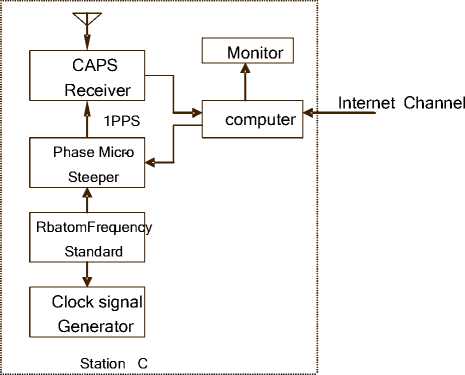
Figure 4 The time synchronization system
Rubidium clock is selected as the frequency standard with the frequency output of 10 MHz. All the characteristics including accuracy of the output frequency signals, frequency stability, frequency drift, harmonic distortion, phase noise and the performance of switching on for preheating are designed to meet the specifications.
A PC computer at station collects the GEOPS timing data from the other station and calculates the time differences.
The micro phase stepper at each station steers the frequency according to the time differences received from the station to the requested accuracy. The module for this module consists of a divider of 107 and a frequency shifter of 108~109. The divider divides the standard frequency of 10 MHz into 1pps. The 1pps signals can be shifted under the control of a Computer with the shift range 000000~999999.9 μ s. When the time system is initialized, the 1pps output from the GEOPS is used to synchronize the frequency divider roughly under the control of the computer with the precision better than 1 μ s. The frequency shifter works to precisely shift the phase with the shifting range of 108~109 controlled by the computer. The output 1pps from the shifter is requested to be synchronized with the 1pps output from the shifter of the other stations to the precision of 10 ns.
The clock signal generator is to produce the Beijing Time with year, month, date, hour, minute and second by using a divider. After the time system is initialized, the module receives the serial time encoded information from the GEOPS receiver to calibrate the time and date and to convert UTC ant Beijing Time in dual way automatically.
Equation (14) shows that the error increases with the increasing distance between the navigation upload station and the user. If the ephemeris error is 2 m, the user is 5000 km away from the navigation upload station, and then the remaining ephemeris error after the pseudorange difference of the virtual clock is 0.3 m.
The ionosphere pseudorange error is given by (15).
40.3
^Pion = "Jr TEC
Here, TEC is the total number of electrons along the path from the transmitter to the receiver. f is the carrier frequency.
Because the ionosphere delay is in inverse proportion to the frequency square for the GNSS signal, the ionosphere pseudorange error of GEOPS signal is less than other GNSS signal along the same path. The frequency points in GEOPS are upload C1 = 6368.15±15 MHz and C2=6051.02±15 MHz, download C1=4143.15±15 MHz and C2=3826.02±15 MHz[7]. The L1 frequency point in GPS is 1575.42MHz. The C1 ionosphere delay of GEOPS is 0.1446 times that of GPS, and the C2 ionosphere delay of GEOPS is 0.1696 times that of GPS. The ionosphere delay correction model devised by J.A.Klobuchar is referred to as a GEOPS ionosphere model. By using dualfrequency GEOPS receiver, the ionosphere delay can be cancelled out through the use of the frequency dispersion characteristic of ionosphere delay.
D. The error consideration based on GEOPS common view
GEOPS adopt a new method for determination of satellite orbits by transfer. The ranging accuracy is very high. It can be better than 1 cm for ranging accuracy and 9 cm for the residuals of orbit determination. The precision of orbit determination is better than 2 m[7]. This means the ephemeris errors is less than 2m.
The satellite virtual atomic clock has the function of pseudorange difference to remove most of the ephemeris errors[4]. The remainder error is shown by (9).
Moisture and oxygen in the troposphere have an effect on the velocity of propagation of the GEOPS signal. This effect is dependent on the geometry, the latitude, the pressure, and the temperature, and may vary in magnitude from 3ns to 300ns[3]. In GEOPS receiver, the troposphere delay correction model devised by Hopfield is referred to as a GEOPS troposphere model[9]. The troposphere delay error is shown by (16).
^Peph =
eph ( sat )
)2 + (ya
y eph ( sat )
) 2 + ( Zat
z eph(sat)
)2
( X$at — Xst a) 2 + ( Уа ~ У st a) 2 + ( Zsat ~ 2sta2 sat sta sat sta sat sta
■ V( Xu - xsta ) 2 + (yu - ya ) 2 + ( z u - z sa ) 2
^P = 1 W
Ptrop sin( E 2 + 6.25) 1/2 sin( E 2 + 2.25) 1/2
Kd = 1.552 x 10~ 5 ^^^( h - h ) ddu
T k
K w = 7.46512 x 10 - 2 e_ ( h w - h u )
k hd = 40136 + 148.72(Tk - 273.16)
h W = 11000
( 16 )
Where x sat , y sat , z sat are the actual position of the satellite, x eph ( sat ), y eph ( sat ) , z eph ( sat ) are the ephemeris position of the satellite, x sta , y sta , z sta are the position of the master control station, and x u , y u , z u are the user position.
As described above, Common view based on GEOPS cancels out the signal propagation delay from the master clock to the satellite, and the signal propagation delay from the master clock to the satellite is not influence of time transfer. The satellite virtual atomic clock has the function of pseudorange difference to remove most of the ephemeris errors, and the method for determination of GEOPS satellite orbits makes ephemeris errors smaller, so they insure highly precise time transfer. Common view based on GEOPS can cancels out most of the ionosphere delay
and the troposphere delay. In GEOPS receiver, the effectively ionosphere delay correction model and the effectively troposphere delay correction model is helpful to reduce errors from the ionosphere delay and the troposphere delay. So it can be concluded that common view based on GEOPS is a good choice for highly precise time synchronization.
-
[4] Ai G X, Shi H L, Wu H T, et al. The principal of the positioning system based on communication satellites. Sci China Ser G-Phys Mech Astron, 2009, 52(3): 472 - 488.
-
[5] Hu Y H, Hua Y, Hou L, et al. Design and implementation of the CAPS receiver. Sci China Ser G-Phys Mech Astron, 2009, 52(3): 445 - 457.
-
[6] Li X H, Wu H T, Bian Y J, et al. Satellite virtual atomic clock with pseudorange difference function. Sci China Ser G-Phys Mech Astron,2009, 52(3): 353 - 359.
-
[7] M. A. Lombardi, L. M. Nelson, A. N. Novick, V. S. Zhang, Time and Frequency Measurements Using the Global Positioning System, Cal. Lab. Int. J. Metrology, pp. 26-33, (July-September 2001).
-
[8] Li Z G, Yang X H, Shi H L, et al. A new method for determination of satellite orbits by transfer. Sci China Ser G-Phys Mech Astron, 2009,52(3): 384 - 392.
-
[9] Lu X C, Wu H T, Bian Y J, et al. Signal structure of the Chinese Area Positioning System. Sci China Ser G-Phys Mech Astron, 2009, 52(3):412 - 422.
References Research on the time synchronization technology based on the GEO Positioning System
- Li Z G, Li H X, Zhang H. The reduction of two-way satellite time comparison. Chin Astron Astrophys, 2003, 27:226—235 [DOI]
- Merck ] P, Achkar J. Typical combined uncertainty evaluation on the Ku band TWSTFT link. In: Proceedings of
- the 19th European Frequency and Time forum (EFTF), 2005D. W. Allan, M. A. Weiss, Accurate Time and Frequency Transfer During Common-View of a GPS Satellite, 34th Annual Frequency Control Symposium, pp. 334-346, May 1980.
- Ai G X, Shi H L, Wu H T, et al. The principal of the positioning system based on communication satellites. Sci China Ser G-Phys Mech Astron, 2009, 52(3): 472 -488.
- Hu Y H, Hua Y, Hou L, et al. Design and implementation of the CAPS receiver. Sci China Ser G-Phys Mech Astron, 2009, 52(3): 445-457.
- Li X H, Wu H T, Bian Y J, et al. Satellite virtual atomic clock with pseudorange difference function. Sci China Ser G-Phys Mech Astron,2009, 52(3): 353-359.
- M. A. Lombardi, L. M. Nelson, A. N. Novick, V. S. Zhang, Time and Frequency Measurements Using the Global Positioning System, Cal. Lab. Int. J. Metrology, pp. 26-33, (July-September 2001).
- Li Z G, Yang X H, Shi H L, et al. A new method for determination of satellite orbits by transfer. Sci China Ser G-Phys Mech Astron, 2009,52(3): 384-392.
- Lu X C, Wu H T, Bian Y J, et al. Signal structure of the Chinese Area Positioning System. Sci China Ser G-Phys Mech Astron, 2009, 52(3):412-422
