Research on Virtual Vehicle Driven with Vision

Author: Youquan Liu, Yu Cui, Enhua Wu
Journal: International Journal of Information Technology and Computer Science(IJITCS) @ijitcs
Article in issue: 4 Vol. 3, 2011.
Free access
This paper presents a traffic-oriented modeling and simulation framework. With this tool, users can create a traffic scene quickly and easily, and then drive the vehicle in the created scene with physics simulated. Especially, the vehicle could be driven with vision technology, which is equipped with a webcam and a paper printed with controlling markers. And the paper is used as the virtual wheel to control the motion of the vehicle. At such low cost, many people can enjoy the driving fun; it also provides an easy and interesting way for driving video games with promising business values.
Camera, traffic modeling, vision interaction, vehicle driving, simulator
Short address: https://sciup.org/15011632
IDR: 15011632
Text of the scientific article Research on Virtual Vehicle Driven with Vision
Published Online August 2011 in MECS
As one of the most important virtual reality environments, driving simulator provides users a useful tool for training and digital entertainment. With such kind of systems, people could attain driving experience safely at low cost or get fun easily. And it is also capable to evaluate the drivers’ performance. The National Advanced Driving Simulator at the University of Iowa and the Toyota one are among the largest ground vehicle driving simulator in the world[1]. However because these industrial simulators are equipped with complex electro circuit system, mechanical and fluid drive systems, they are expensive and only available to professionals.
For ordinary people, the way to get driving fun is to play video games, like 3D Driving-School [2], Need for Speed [3], Euro Truck Simulator [4] etc. And often keyboard and mouse are the interaction devices; further joysticks like simulation steering wheel are used to achieve more realistic driving experience.
In traffic area, camera is often used as video capture device, for example, Ono et al. [5] used camera to capture the real scene and combine the real image with the virtual geometry data to give a more realistic rendering for driving simulation.
Beside capturing video, camera sometimes is also used as an interaction way in digital entertainment area, such as Eyetoy[6] by Sony, Kinect[7] by Microsoft, gesture interaction. It is seldom used to control the motion of a complex virtual object, such as virtual vehicle. The closest work to ours is that a game from GoArmy website[8], it provides a driving game which is controlled by webcam. However it just provides limited steering only.
In this paper we present a framework to model the traffic scene and drive the vehicle. With such a tool a scene could be set up easily with physics dynamic properties. And a mixed reality based virtual driving method with camera controlling is illustrated, which gives an innovative interaction way to control the vehicle in the computer-generated environment. Instead of other expensive interaction devices, we are using the cheap webcam as the interaction device, which is also almost available in every computer system. Beside the vision controlled dynamic simulation of driving, a traffic-oriented visual modeler is also presented. With this tool, a city traffic scene can be constructed quickly.
With a printed paper visible in front of webcam, we reconstruct the spatial coordinates of the marker located from the captured 2D image, and then calculate the angle change from the framework which is used as the steering; and some other markers used to control the braking, backing, honking operations. Such kind of way provides users an interesting interaction mode for vehicle driving, which is cheap and available to many users. And there is not much limitation to the position of the webcam, and the only restriction is that the markers on the paper should be visible to the webcam.
In the following section the whole system will be described firstly, and then traffic-oriented visual modeler and the vision interaction will be discussed in Section 3 and Section 4. The last two parts will give our experiment and discussion.
-
II. System design
As a driving simulation framework, our system consists of two parts, the first one is the visual city traffic modeling tool, which is used to interactively design the city traffic scene quickly. The second part is the webcam interaction tool to control the driving.
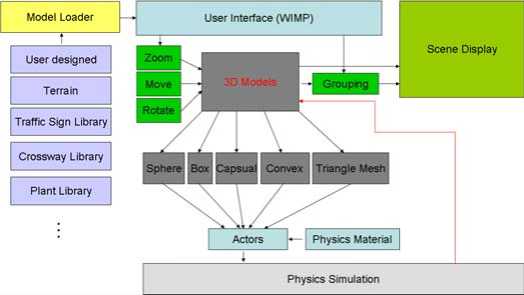
Figure 1. Framework of traffic oriented modeler sub-system
Obviously the modeling tool can be designed separately to avoid developing complexity. Fig.1 presents the scheme of our traffic oriented modeler system. With this modeler, we can create a scene with traffic information quickly. Different from other general 3D modeling tools like 3DS Max, this tool is designed specially for the purpose of city traffic. This part will be discussed in detail in Section 3.
In Fig.2, the scheme of the webcam controlling subsystem is given. The interaction device is the webcam with a common paper printed with markers, as shown in Fig.10 the virtual vehicle is controlled with a paper. By rotating the paper under the camera, we can steer the direction of the vehicle. And by alternating the visibilities of some markers with hands, we can do some pre-defined operations, such as backing, honking, braking, and shifting. This will be discussed in detail in Section 4.
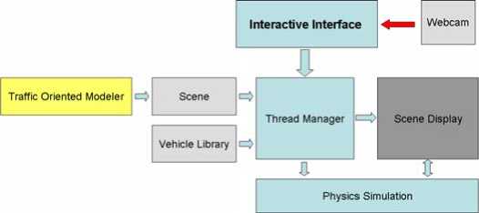
Figure 2. The webcam controlling sub-system scheme
In both sub-systems, to give the realistic motion information, we integrate the physics effects into the scene so that collisions could be detected and responded realistically.
-
III. traffic-oriented visual modeler
As described above, the traffic-oriented visual modeler provides users an easy way to create a city traffic scene quickly. Fig.3 gives a scene designed with our modeler. In Fig.3, its function modules are illustrated. With this tool, we can load the external models designed by others and put them together with dynamic properties.
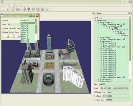
Figure 3. Interface of the Traffic Oriented Modeler
With physics from PhysX[9] integrated, the new added components will be placed rationally without crossing or overlapping, reducing users’ burden to adjust their positions. And their physics properties can be also set up conveniently which will be used for dynamic driving, such as mass, friction etc. So the created scene is dynamic with vehicles moving.
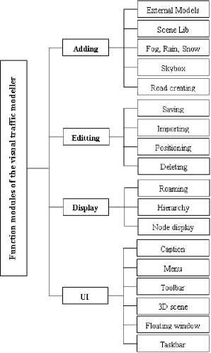
Figure 4. Function modules of the modeler
To facilitate the modeling of traffic scene, we also provide a special pre-designed library which includes many traffic signs, different crossways, plant sights, users only need to click and drag in most situations as shown in Fig.. Fig.4 gives one example.
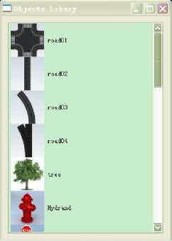
Figure 5. Pre-designed library with many components
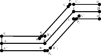
Figure 7. The initial points with mouse input at A, B, C, D
To avoid the problem mentioned above, the contour technique is used to construct the geometry mesh of the road.
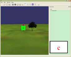
To help users to manipulate the objects in convenient way, several draggers are provided, such as Plane Dragger which constrains the motion on the plane, Trackball Dragger which controls the rotation of the object, Translating Dragger which translates the object in 1D, 2D or 3D space, Box Dragger as the most complex dragger which is used to scale or translate the object. Fig. 6 illustrates that the stop sign model is adjusted to the proper size and orientation.
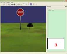
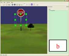
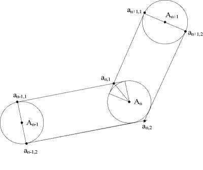
Figure 8. The geometry generation for the road
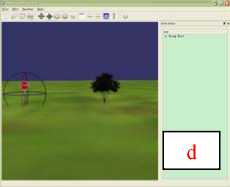
Figure 6. Example of manipulating with two draggers from a-b-c-d
As shown in Fig.8, point A n-1 , A n , A n+1 are defined with mouse clicks. To construct the road surface, the boundary points a n-1,1 , a n-1,2 and a n+1,1 , a n+1,2 are calculated firstly, and then the boundary points a n,1, a n,2 of A n is calculated. Because line segment a _ a is normal to
line segment An-1An , similarly, a n + 11 a n + 12 is normal to
A n A n+1 . With the road width w , the coordinates of a
' n - 1,1 ,
a n - 1 2 , a n + 1 1 , a n + 1 2 can be calculated with the following
equations.
We can not create a city model without road. So road geometry construction is necessary. However manual road construction is tedious obviously. In this paper we present an easy way to minimize the labor by just mouse clicking at key points. With simple clicks, key points of the road are defined as shown in Fig.7, like A, B, C, D. Obviously, if we just extend the road width along the normal direction as in Fig.7, some parts will get collided like P 1 , P 2 , some parts will break like P 3 , P 4 .
|
a x = A x + w * A n . У - A n - 1 . У |
|
|
,1 n 1 7( A n . У - A n - 1 . У )2 + ( A n . x - A n - 1 . x )2 |
|
|
1 У = A 1 У w * , A n . x - A n - 1 .x ____________ |
|
|
n 1 |
|
|
7( A n . У - A n - 1 . У )2 + ( A n . x - A n - 1 . x )2 |
|
1 n - 1,2-
. x = A n - 1 . x - w *
_____________ A n . У - A n - 1 . У _____________ 7( A n . У - A n - 1 . У )2 + ( A n . x - A n - 1 . x )2
. У = A n - 1 . У + w *
a n + 1,1 . x = A n + 1 . x
A . x - A . x n n — 1
7( A n . У - A n - 1 . У )2 + ( A n . x - A n - 1 . x )2
_____________ A n + 1 . У - A n . У _____________ 7( A n + 1 . У - A n . У )2 + ( A n + 1 . x - A n -x )2
a n + 1,1 . У = A n + 1 . У + w *
A n + 1 . x - A n . x
7( A n + 1 . У - A n . У )2 + ( A n + 1 . x - A n . x )2
I n + 1,2 . x = A n + 1 . x + w *
A n + 1 . У - A n . У
•J ( A n + 1 . У - An . У )2 + ( A n + 1 . x - A n -x )2
a n + 1,2 . У = A n + 1 . У - w *
A n + 1 . x - A n . x
( A n + 1 . У - A n - У )2 + ( A n + 1 . x - A n . x )2
To a n ,1 , a n ,2 these two corner points, special processing is needed. The common tangents of circle An- and An, An and An+ are found to intersect to get
a n ,1 , a n ,2 as shown in the following equations.
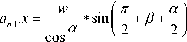
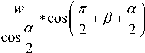
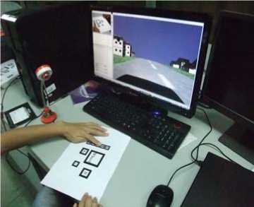
Figure 10. The user interface of virtual driving
where
a = arctan
A n + 1 . У - A n - У A n + 1 . x - A n . x
в = arctan
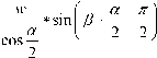
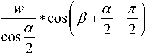
A n . У - A n - 1 . У .
A n . x - A n - 1 . x
- arctan
4.1 Framework of coordinate system
Since webcam is used to capture the motion of the paper with markers, there are three frameworks used, world, camera, image space. The relationship among these three frameworks is shown in Fig.11.
A n . У - A n - 1 . У
A n . x - A n - 1 . x
After these steps, the key points of the road geometry are ready. To construct the geometry mesh of the road, Delaunay triangulation is used to construct the final mesh so that it can be integrated into physics world. Here just 2D equations are given to calculate the vertices of the mesh, however it is straightforward to extend them to 3D space. And texture mapping is used to enhance the realism. With different textures and widths we can construct different lanes road as shown in Fig.9.
With computer vision knowledge, webcam is modeled with pinhole assumption. So a point in 3D world space can be transformed into image space with the following equation:
u s • v
fx 0
0 f y
cx r11 r12
c - r. r..r..
СУ r21 r22
1 _ _ r31 r32
t 1
•
' 3 .
w Y w Z w 1
where ( Xw , Yw , Zw ) is
the 3D world space point, ( u , v ) is
its according image point in pixel metric. And fx ,
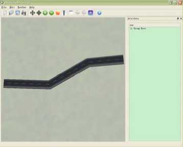
Figure 9. Road constructed with simple clicks
fy are the focal distance in pixel metric, ( cx , cy )is the base point(often located in the center of the image). Equation 1 could be written further as follows,
xc yc zc
= R •
X w
Y w Z w
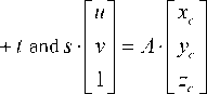
where A is the internal parameter matrix, or camera matrix which used to describe the internal parameters of the camera and independent of the scene. Once it is calibrated, it could be used repeatedly when its focal distance fixed. Transformation matrix [ R 1 1 ] is the
external parameters matrix which consists of translation and rotation. It is used to describe the rigid motion of the camera in the scene.
IV. Vechile driven with vision
The vision based interaction is the key part of our innovation. All interaction information comes from the webcam. Therefore, an effective recognition algorithm should be available firstly. In our system ARToolKit[10] is used as the vision capturing API. It locates the position of central marker used to restore the rotation information serving as steering angle. With ARToolKit API the visibilities of surrounding markers are translated into commands used to control the vehicle. The details will be given below.
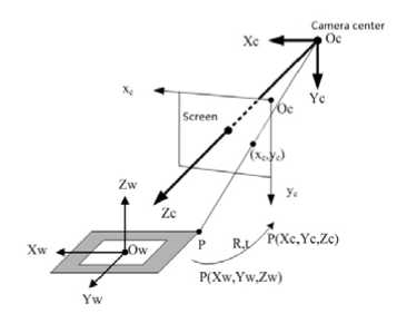
Figure 11. The relationship among the three coordinate framework
With the help of ARToolKit API, we can capture the world position of the markers. But to control the steer of vehicle, the world position has to be transformed into angle information. Fig.6 presents the virtual wheel used in our system, certainly it is a common paper printed with different marks, which are labeled with red circles.
Steering
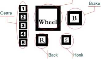
Figure 12. Markers distribution
The captured information includes the location of the central marker, the visibility of other markers. The steering is controlled by the central marker labeled with Wheel, its location relationship matrix between world framework and image space could be written as,
' X x У х Z x P x '
x y У у z y P y
X x z Ух z z P z у
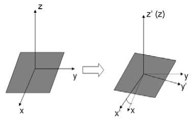
Figure 13. Rotation angle calculation
With the following analysis we can separate the steering angle from this matrix:
(1)The first three columns are the x, y, z axis vectors respectively.
-
(2) Since the paper moves on the desktop, we can calculate the rotation of x axis from dot product of the x axis of front frame and back frame as shown in Fig.7. To get the exact rotation angle, we use the x axis vector of the first frame as the original reference x0. By calculating x f ■ x 0 , X b ■ x 0 , the delta angle between the front frame and back frame is A a = arccos( x f • x 0) - arccos( x b • x 0) .
(3)However the angle directly calculated from dot product is uncertain. we have to transfer the angle to [-π, π] since the vehicle can turn left or right arbitrarily. Here we calculate x ■ y 0 at the same time, which is used to determine the direction. After we get the angle, then steering of vehicle could be done.
Except the steering of vehicle, other behaviors are controlled by the visibility state of according markers to the camera. If some marker is occluded by hand or something else, its state will change from visible to invisible, that’s, some according operation will be executed. The control of speed is realized by the left number sub-markers. The number of visible number submarkers indicates the gears. Less visible sub-markers, less speed will be.
Back, brake, honk these three operations are the simplest cases in our system, which are associated with marker R , B , S respectively. If maker R is invisible in the camera, then the vehicle will stop and then back up. If maker B is invisible, the vehicle will be braked to take a stop. S means a honk.
-
V. Scene display and physics simulation
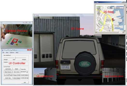
Our display is based on OpenSceneGraph[11], which is used both in the city modeling and virtual driving. Fig.14 gives a simple demo scene created by our modeling tool with more than 5000 vertices. Since the scene data are independent of the driving simulator, our system can also incorporate other data like the Boston city model as shown in Fig.15, which comes from [11] with 0.6M vertices. Because the 3D scene can only provide the driver the local view around the cab, to provide the global position information, 2D map is given which is consistent with the 3D scene. Taking the Boston scene as an example, the system integrates Google Map as the 2D map as shown in Fig.15. As a result, the driver not only can watch the scene following the vehicle, but also can locate the position in the whole city with GIS information. As another consideration, to provide the back view cameras, two more views are used to display the scene which means the scene will be rendered in two more passes. For realistic motion, PhysX is integrated into the framework to provide physical reasonable collision detection and response, such as the effects between vehicle and environment, vehicle and vehicle, the vehicle’s shaking, et al.
-
VI. Experiments and discussion
The whole system is developed with Visual Studio 2005, C++. The scene is displayed with OpenSceneGraph, physics effects with PhysX, UI with Qt for the modeler, and 2D map with Google map API by HTML + JavaScript. The machine is equipped with Intel Quad CPU Q8300@ 2.50GHz and NVIDIA GeForce 9800 GT graphics card. As to the Boston scene, the number of triangles is more than 0.6M with three views enabled. The frames per second are above 60.
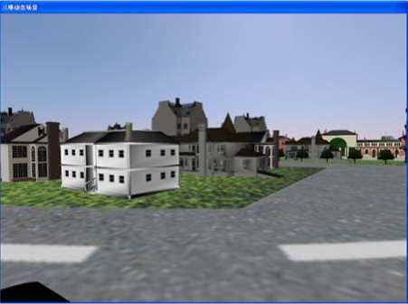
Figure 14. Simple scene set up by our modeling tool
Though it is not realistic enough compared to professional simulators or simulation steering wheels, it is different, interesting and better than the keyboard-mouse way. Such kind of driving pattern gives a novel way for driving, which could be used in other types of video games, not only in driving games. It should have potential business values.
However, the limitation of this method is also obvious. It can not provide realistic operation feeling with force feedback. And it also is easy to be influenced by the lighting environment. These drawbacks constrain its applications in the digital entertainment, away from professional driving simulators.
In the future work, we would like to integrate GIS into our modeler to enable adding much useful information to drivers. Other visual features will also be added to the modeler to provide a more realistic virtual environment. And the traffic simulation will be integrated into the system to simulate the traffic flow with many vehicles.
2p Map,
UI Controller
Figure 15.
Whole system interface with Boston scene
-
VIII. Acknowledge
The work is supported by the National Grand Fundamental Research 973 Program of China (No.2009CB320802), National Natural Science Foundation of China (No. 60973066, No.50978030), Program for Changjiang Scholars and Innovative Research Team in University(No. IRT0951).
References ,2010.
,2010.
References Research on Virtual Vehicle Driven with Vision
- http://en.wikipedia.org/wiki/Driving_simulator,2010.
- http://www.3dfahrschule.de/uk_index.htm,2010.
- http://www.needforspeed.com/,2010.
- http://www.scssoft.com/,2010.
- Shintaro Ono, Koichi Ogawaray, Masataka Kagesawaz, Hiroshi Kawasakix, Masaaki Onuki,Junichi Abeki, Toru Yano, Masami Nerio, Ken Hondak and Katsushi Ikeuchi, “A Photo-Realistic Driving Simulation System for Mixed-Reality Traffic Experiment Space,” Proceedings of IEEE Intelligent Vehicles Symposium, 2005.June 2005, pp.747 - 752.
- http://en.wikipedia.org/wiki/EyeToy,2010.
- http://en.wikipedia.org/wiki/Kinect ,2010.
- http://www.goarmy.com/raceforstrength,2010.
- http://www.nvidia.com/object/physx_new.html , 2010.
- http://www.hitl.washington.edu/artoolkit/, 2010.
- http://www.openscenegraph.org/,2010.
- http://www.triangraphics.com,2010.
