Research the influence finishing canal shape to flow media for abrasive flow machining process

Author: Levko V.A., Lubnin M.A., Snetkov P.A., Pshenko E.В., Turilov D.M.
Journal: Сибирский аэрокосмический журнал @vestnik-sibsau
Section: Технологические процессы и материалы
Article in issue: 5 (26), 2009.
Free access
Visual research flow media nature as with abrasive tool put in to practice. To establish facts the influence degree finishing canal shape and form losses for flow character. The guidelines for processing environment leveling developed.
Abrasive flow machining, improved surface quality, flow of abrasive media, visual research, form losses, cross-sectional shaped
Short address: https://sciup.org/148176110
IDR: 148176110
Text of the scientific article Research the influence finishing canal shape to flow media for abrasive flow machining process
The analysis of constructional features of aircraft’s details has revealed the presence wide nomenclature of passageways with cross sections of various shapes and the presence of different local resistances like blades, form losses, etc. 28 standard elements with different geometrical shape of cross sections, which can be found in aircraft, were discovered.
The main purpose of visual research was the fixing the process of abrasive media flowing in channel’s different configuration and its flowing of different local resistances, and the fixing of pressure media’s measurement Input P 1 and output P 2 sample.
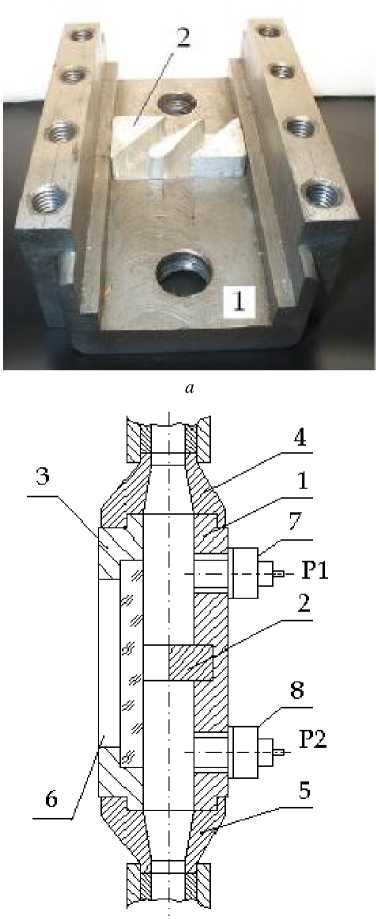
The device was for the visual studies (fig. 1). It consists of the body 1 , in which the groove set specimens-simulators 2 , caps 3 and two adapters 4 and 5 .
For the experiments the media was used with this composition: Silicon rubber (GOST 14680-74) - 48 %, PTFE-4 - 2 %; black silicon carbide 53 C (grain size = 250 microns) - 50 %. Visually, the media of this composition has a dark gray color. On its surface, placed in a device, rectangular mesh size 15 × 15mmandadepthof2mm, which is filled with white fused 25A with grain size = 250 microns, applied by the bursting pattern. White mesh has a good contrast with the surface of media, which provides a clear picture. The Scheme of application (fig. 2) simulates a chain of abrasive grains. Filming was carried out with a speed of 48 frames per second at high contrast, negative film.
Based on studies of the flow on the waveform, film, photographs and scratches at the window 6 of Plexiglas identified characteristics of media, evaluated and the degree of deformation grid on, and direct observation of the flow. Figure 3 shows the flow patterns and schemes of the media in the tested channels. The arrows indicate the direction of flow, a dark color - the stagnant zone.
Each sample has a definite influence on the flow, the value of which can be expressed by the coefficient of local resistance ξ m
ξm= ξcg+γc/Re, where ccg - coefficient of configuration geometry flow; Yc - dimensionless velocity gradient; Re - the Reynolds number.
b
Fig. 1. Fixture for visual research off abrasive flow machining: a – casing with model; b – fixture diagram
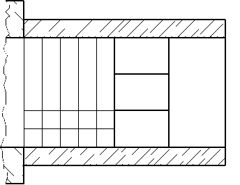
Fig. 2. The grid on the surface environment, modeling the chain of abrasive grains
For the case of AFM Y c = 0.01...0.1 and Re << 1. It can take c m ® C cg. Consequently, the coefficient C cg characterizing the flow pressure loss in passing through this channel will determine the amount of local losses flux in AFM, i. e. C cg » P 1 P 2 .
Studies show that the greatest pressure loss experienced in the flow cone channels (№ 5...7). The coefficient c c takes values of 20.0...23.5.
Toothing with 12 triangular channels ( 28) creates a pressure differential 5.2. For channels with different blades (№ 17...26) C cg varies from 1.8 to 2.1.
When processing channels with a small inlet ( 3,4) pressure loss is reduced more than twice, but the magnitude of the coefficient c cg - 8.4...10.0 remains significant. If the inlet channels with a small inlet is rounding or chamfer ( 8, 9), the value C cg reducedto 3.4...3.7.
For channels with local resistance ( 10...15) the value has a value of 1.4...3.0 depending on the type of resistance. For the three parallel channels ( 16) the pressure drop was 2.3.
These values c cg can be used to assess the influence of the channel cross section shape and type of local resistance to the pressure drop of the working environment at AFM. The value c cg in this case is relative, because it does not take into account the pressure loss along the length of the sensor 7 to the sample and from sample to the sensor 8 (fig. 1).
Figures 4...12 show photographs illustrating the content of the film process medium flow through some of the samples. The direction of flow from left to right.
Sample number 1 (fig. 4) is a local narrowing the channel from the direct gap of half-cylinder. At the initial moment the flow in the center of the channel environment without encountering obstacles, begins the process of shear flow in a half-cylinder. Thus there is a deformation of the grid – elongation of the axis of flow and contraction in the transverse direction. In those places where the environment rests on the front side surface of the sample, the flow of environment is not present.
At this point in the environment the profile of media is changing and two zones with different conditions of deformation are formed. In the zone of shear flow observed steady shear flow. The character of variation of the grid shows a gradient flow, which can be described by the hydrodynamic theory. Stress of elastic chain can be described by the Kargin– Slonimsky–Rouse models [1].
In the second zone there is compression of the chain. The magnitude of compression depends on the elastic properties of the chain. Thus, in the medium two zones with different conditions of deformation are forming. In the first zone tensile stress is observed, in the second zone – compression stress.
When reaching a certain critical value, there is a shift environment in zone 1 on the medium in zone 2. Clearly the boundary between zones 3 is visible. At this point flow profile finally formed and in zone 1 tensile stress drops into the shear flow 4. This transition is clearly apparent in the oscillogram.
ThenallofalargepartofthemediaisfondofZone2in the flow when the piston moving in the working cylinder. However, just before the obstacle in zone 2 of stagnation zone is formed. In the sample stagnation zone is not formed,
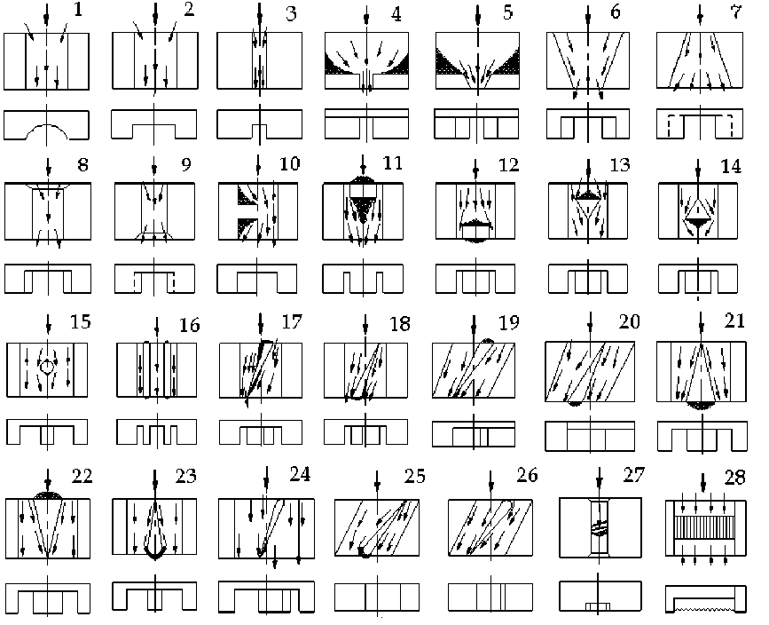
Fig. 3. Scheme of the flow media in the channels of Designs
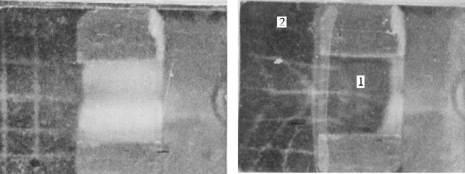
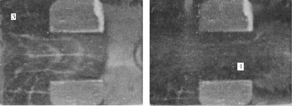
Fig. 4. The process of flow in the sample number 1
contact the media is carried out over the entire surface of the sample. The use of leveling devices is not required.
At the end of the medium the sample the effect of elastic recovery of the jet is observed, which is indicating accumulated in the flow of elastic deformations. This effect is described in detail previously [2]. Especially this effect is clearly manifested at the expiration of the channels of small dimensions, such as in samples number 3, 4 and 5.
If within the medium in conical ducts with variable crosssection flow pattern different. Consider the flow in a diffuser - sample number 6 (fig. 5) and in effuser – sample number 7 (fig. 6). Uneven treatment due to the nature of shear flow environment in the conical channel.
When the medium flow in the diffuser noticeable decrease in the rate of the conical part and a smooth restructuring of the flow profile. The normal stresses accumulate, and the tangent decrease. The pressure in the conical part increases and the flow rate and velocity gradient decreases. In steady the maximum flow pressure on the wall of the channel observed in the cross section with a minimum size, ie on the exit edge of the channel. If such a motion is possible to provide a uniform flow of the processing and removal of metal within a specified allowance in the cylindrical part of the channel.
At the entrance flow in a conical part effuser channel in the initial moment of time there is separation of high-flow environment of the tunnel wall. This phenomenon is a relatively short period of time 0.2...1.1 seconds.
At the same time, in the medium relaxation of accumulated stress occurs and the effect of elastic recovery of the jet begins to manifest itself, i. e. increase in its size and the gradual filling of the total volume of processed feed.
Instant transition from anguish to the free flow jet is for transition edge. At this point, the value of relaxation of elastic strain accumulated in the medium during the flow in the cylindrical part, is maximal. At the edge of the transition, there is a maximum pressure of the flow on the wall of processed feed.
The uniformity of treatment in the conical channel equalization without using special devices to make difficult, since the change in flow profile is directly processed channels. In the special case of flow can be identified based AFM unidirectional diffuser.
In flying apparatus there are details of structural elements, which can be attributed to local resistance. In these studies, these are examples of resistance number 10... number 15.
Channel flow with the lateral wall (fig. 7), characterized by displacement of the medium flow 4 from the central axis of the channel. In this case the inlet there are not two, but three dead zone 2. Two are inlet channel and one is front wall. Behind the observed flow separation from the wall of the treated feed. Because of the effect of elastic recovery is gradually filling the entire volume of the test channel, including and beyond the partition. After completing this section of the channel environment it appears dead space. The bulk of the flow slides along the border of this zone. Processed only the surface of walls, which is parallel to the main stream.
Another form of local resistance, which appears in the details of flying apparatus, is a rectangular resistance at the inlet and outlet channels (fig. 8).
Peculiarity of the flow in this sample is to divide the flow into two parts. Forming two zones of dilation 1 and three
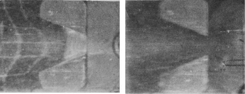
Fig. 5. The process flow in sample number 6 (cone)
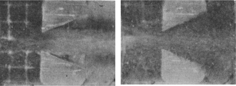
Fig. 6 Process flow of the sample number 7 (effuser)
compression zone 2. Two of these zones are located on the side of the entrance to the processed feed, and another – on the front surface of the rectangular resistance. After the start of shear flow formed two zones within 4 to form the output of the channel bands of elastic recovery 5.
Details of the flying apparatus are characterized by the presence of several parallel arranged relative to each other channels, with identical geometric characteristics. Figure 9 shows that the flow profile is formed at the entrance to the channels. On the flat front edges of the channels formed stagnant zones. Expendable Pressure-flow characteristics in the channels are almost identical.
Various blades are the basic structural elements of aircraft and rackets parts. In the studies presented samples of blades number 17... number 26.
The flow in straight rectangular channel with a sloping shoulder blade with a straight forward basis (sample number
-
17) is shown in Figure 10. Blade breaks straight rectangular channel into two parts with variable cross-section shape. In this case, in the channels among modes of deformation are different. In having a smaller area of the inlet the expanding part of the channel observed deformation zone 1 elongation medium.
In having a greater cross section of the inlet of a shrinking part of the channel in the central part of the observed elongation zone, which is to the walls of the channel is replaced by a zone of compression. Stagnant zone 2 observed on the surfaces perpendicular to the main direction of deformation of the medium.
After adjustment profile in the zones of tensile strain – compression of the deformation of 4 shear flow environment with the subsequent effect of elastic recovery 5. The main processing occurs in sections with a smaller area.
Another flow pattern is observed in AFM’s environment inclined channel with sloping shoulders. Flow of the medium
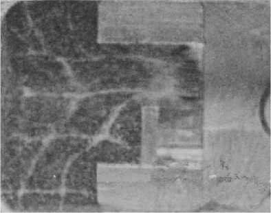
Fig. 7. The process flow in the sample number 10 (bulkhead)
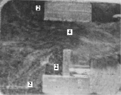
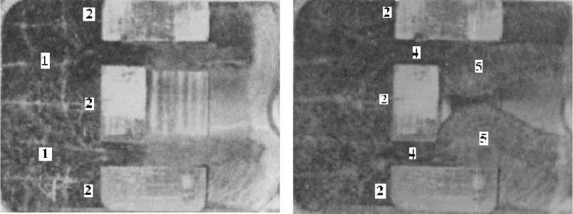
Fig. 8. The process flow in the sample number 11 (obstruction at the entrance)
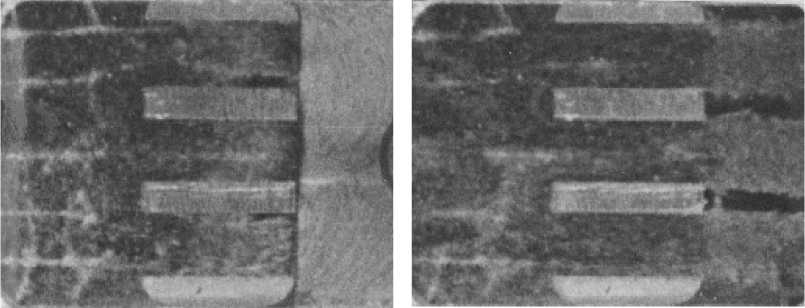
Fig. 9. The process flow in the sample number 16 (parallel channels)
in an inclined channel with a sloping shoulder blade with a straight forward reason – sample number 19 (fig. 11). Since the investigated channel has an angle of inclination relative to the central axis of the working cylinder, and changing the direction of flow.
Restructuring flow profile environment is at the entrance to the processed feed. There two dead zone 2 and two zones of dilation 1 are forming. After reaching a critical value in zones 1 strain is replaced by a shear flow in two parts, the channel also implemented a process of shear flow in zones 4 with subsequent elastic restoration of the environment in zone 5.
Flow separation with a sharp front edge is not observed. The entire surface of the channel is processing except for a direct cause shoulder at the entrance to the channel. The size of the stagnation zone 2 during the entire process of processing does not change.
In a separate group of flying apparatus parts are structural elements that have a large channel L length and small cross- section S with ratio L/S >> 1. When flow through a small cross section (fig. 12) in the channel has created a complex grains, preventing the flow shear.
The piston operating cylinder could not provide the necessary amount of shear stress and there was jamming Abrasives. For AFM such channels must use the abrasive medium special formulations with reduced viscosity.
According to the research design elements on the processing conditions can be divided into five groups.
The first group includes channels with constant cross section (№ 1.. 4, 8, 9, 28), which does not affect the flow. They have small values of the coefficient of the configuration flow ξ cg. Chamfer at the entrance to the channel (№ 8) provides a smooth entry into the media channel, reducing the coefficient ξ cg. Since the channel with beveled (№ 8) ξ cg = 3.4 less than in this channel (№9) withafacetatthe output ξ cg = 3.7. For such channels adjustment stress-strain state of flux carried by a special technique.
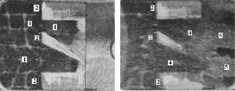
Fig. 10. The process flow in the sample number 17
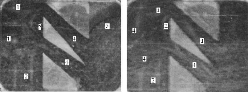
Fig. 11. The process flow in the sample number 19
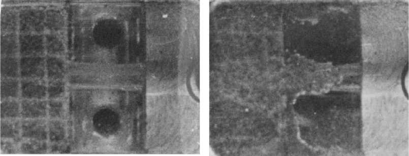
Fig. 12. The process flow in the sample number 23
The second group of cone channels, the loss of pressure medium in which the maximum. For the uniform treatment of such channels is recommended to change the flow regime of the cone to ring slit ( 5...7) or to apply a one-way AFM ( 6).
In the third group, consisting of a channel with the local resistance, AFM’s still rough surface, perpendicular to the flow ( 10...15). For processing to change the direction of flow through the leveling devices.
For a uniform treatment of channels with blades, which are the fourth group ( 16...26), it is necessary to ensure an even flow environment in each of the channels, by forming the flow profile at the entrance of these channels.
In the fifth group included micro, requiring the use of working environments with low effective viscosity and low dispersion of abrasive filler ( 27).
In analyzing the motion of individual abrasive grains in a flow is established that they move along the current lines. In steady flow the distance between neighboring grains is not changed. This confirms the supposition about the formation of elastic chains in the flow [1]. Established that the grain, into contact with the treated surface, the flow performs rotational motion. Studies education media vortices near walls or in the flow with the flow in the channel was not observed.
Research has identified the nature of the flow in channels of different media configurations and taken into account in calculating the roughness of the surface finish and performance of AFM on the previously developed technique [3].
