Robust Fuzzy PD Method with Parallel Computed Fuel Ratio Estimation Applied to Automotive Engine

Author: Farzin Piltan, Fatemeh ShahryarZadeh, Mohammad Mansoorzadeh, Marzieh kamgari, Saeed Zare
Journal: International Journal of Intelligent Systems and Applications(IJISA) @ijisa
Article in issue: 8 vol.5, 2013.
Free access
Both fuzzy logic and computed fuel ratio can compensate the steady-state error of proportional-derivative (PD) method. This paper presents parallel computed fuel ratio compensation for fuzzy plus PID control management with application to internal combustion (IC) engine. The asymptotic stability of fuzzy plus PID control methodology with first-order computed fuel ratio estimation in the parallel structure is proven. For the parallel structure, the finite time convergence with a super-twisting second-order sliding-mode is guaranteed.
Fuzzy Logic Methodology, Computed Fuel Ratio Method, PID Method, Parallel Computed Fuel Ratio Methodology, IC Engine
Short address: https://sciup.org/15010457
IDR: 15010457
Text of the scientific article Robust Fuzzy PD Method with Parallel Computed Fuel Ratio Estimation Applied to Automotive Engine
Published Online July 2013 in MECS DOI: 10.5815/ijisa.2013.08.10
The internal combustion (IC) engine is designed to produce power from the energy that is contained in its fuel. More specifically, its fuel contains chemical energy and together with air, this mixture is burned to output mechanical power. There are various types of fuels which can be used in IC engines namely; petroleum, diesel, bio-fuels, and hydrogen [1]. Modeling of an entire IC engine is a very important and complicated process because IC engines are nonlinear, multi inputs-multi outputs (MIMO) and time variant. One of the most significant challenges in control manage algorithms is a linear behavior controller design for nonlinear systems (e.g., IC engine). All of IC engines which work in industrial processes are controlled by linear PD control management and proportional-integral-derivative (PID) method, but the design of linear control management for IC engines is extremely difficult because they are hardly nonlinear and uncertain [1-2, 6]. To reduce the above challenges, the nonlinear robust methodology (e.g., computed fuel ratio methodology) is used to compensate the linear control of IC engine.
The controller is a device which can sense information from linear or nonlinear system (e.g., IC engine) to improve the systems performance [3]. The main targets to design a control systems are stability, good disturbance rejection, and small tracking error[5]. In automotive industries several IC engines are controlled by linear methodologies (e.g., Proportional-Derivative (PD) methodology, Proportional- Integral (PI) method or Proportional- Integral-Derivative (PID) method), but it has many limitation to have a good result. In some applications IC engines are used in an unknown and unstructured environment, therefore strong mathematical tools used in new control methodologies to design fuzzy plus PD controller based on computed fuel ratio compensation [4-5].
Fuzzy-logic aims to provide an approximate but effective means of describing the behavior of systems that are not easy to describe precisely, and which are complex or ill-defined [7-11, 22]. It is based on the assumption that, in contrast to Boolean logic, a statement can be partially true (or false) [12-21, 23-31]. For example, the expression (I live near SSP.Co) where the fuzzy value (near) applied to the fuzzy variable (distance), in addition to being imprecise, is subject to interpretation. The essence of fuzzy control is to build a model of human expert who is capable of controlling the plant without thinking in terms of its mathematical model. As opposed to conventional control approaches where the focus is on constructing a controller described by differential equations, in fuzzy control the focus is on gaining an intuitive understanding (heuristic data) of how to best control the process [28], and then load this data into the control system [28-31].
Computed fuel ratio methodology (CFM) is a powerful nonlinear optimized compensate method, which it is widely used in control of fuel ratio of IC engine. It is based on feedback linearization and computes the required engine fuels using the nonlinear feedback control law. This nonlinear term is used to reject disturbances and also some classes of mismatches between the actual system and the model used for design
[12, 26-29]. These standard CFMs are robust with respect to internal and external perturbations, but they are restricted to the case in which the output relative degree is one. Besides, the high frequency switching that produces the computed fuel ratio may cause chattering effect. The tracking error of CFM converges to zero if its gain is bigger than the upper bound of the unknown nonlinear function [29-30].
Normal combinations of PD control with fuzzy logic (PD+FL) and computed fuel ratio method (PD+CFM) is design to automotive engine [17], while FLC compensates the control error, CFM reduces the remain error of fuzzy PD to have robust and stable result [18]. The error is reduce, because PD+CFM and PD+FL work parallel. In this paper, the asymptotic stability of PD control with parallel fuzzy logic and the first-order computed fuel ratio compensation is proposed (PD+CFM+FL). The fuzzy PD is used to approximation the nonlinear plant [23-29].
This paper is organized as follows; second part focuses on the modeling dynamic formulation based on Lagrange methodology, fuzzy logic methodology and computed fuel ratio controller to have a robust control. Third part is focused on the methodology which can be used to reduce the error, increase the performance quality and increase the robustness and stability. Simulation result and discussion is illustrated in forth part which based on trajectory following and disturbance rejection. The last part focuses on the conclusion and compare between this method and the other ones.
II. Theory
2.1 IC Engine’s Dynamic:
Dynamic modeling of IC engine is used to describe the nonlinear behavior of IC engine, design of model based controller such as pure variable structure controller based on nonlinear dynamic equations, and for simulation. The dynamic modeling describes the relationship between fuel to air ratio to PFI and DI and also it can be used to describe the particular dynamic effects (e.g., motor pressure, angular speed, mass of air in cylinder, and the other parameters) to behavior of system[1].
The equation of an IC engine governed by the following equation [1, 4, 25, 29]:
PFI1 = [M air !! DI]4M air 2 t
M a i r ! 2
Mai Г2 2
[Pz> -]+[й::
Й -b-Ma'
№+
N
N
]x
Where PFI is port fuel injector, DI is direct injector, Mair is a symmetric and positive define mass of air matrix, Pmotor is the pressure of motor, N is engine angular speed and is matrix mass of air in cylinder. Fuel ratio and exhaust angle are calculated by [25, 29]:
(□-
[FRJ ГМ^ . , Mair , 2
l^aj № ir 2 г Mair 2 2
fc:>^"""lx (2)
I? r-fc111
The above target equivalence ratio calculation will be combined with fuel ratio calculation that will be used for controller design purpose.
2.2 Model free Control Technique
The control problem for IC engines is to determine the port fuel injection (PFI) and direct injection (DI) required causing the fuel ratio (FR) execute a command motion. The objective of the control methodology can be divided into two different categories: regulation and tracking. Regulation problem control is used when the desired trajectory of the end-effector is chosen to be constant by specifying to the final point. Tracking problem consists of following a time varying FR reference trajectory. The model-free control strategy is based on the assumption that the joints of the manipulators are all independent and the system can be decoupled into a group of single-axis control systems [18-23]. Therefore, the kinematic control method always results in a group of individual controllers, each for an active joint of the manipulator. With the independent joint assumption, no a priori knowledge of IC engine dynamics is needed in the kinematic controller design, so the complex computation of its dynamics can be avoided and the controller design can be greatly simplified. This is suitable for real-time control applications when powerful processors, which can execute complex algorithms rapidly, are not accessible. However, since joints coupling is neglected, control performance degrades as operating speed increases and a manipulator controlled in this way is only appropriate for relatively slow motion [31]. The fast motion requirement results in even higher dynamic coupling between the various robot joints, which cannot be compensated for by a standard robot controller such as PD [21], and hence model-based control becomes the alternative. Based on above discussion;
Let us consider V — 0 . This implies that;
FR = 0^FR = 0^ FR
[Maim l_Mair21
x e ^ e — 0
M ■
1 ‘air 12
M ■ ‘‘3^22
]
—1
Kp
е 1 (t) = FRdeslred(t) — FRactua(t) (4)
PFIa = Kpae i + K v aei
2.3 Computed Fuel Ratio Method
Computed fuel optimization (CFM) is a powerful nonlinear optimized supervisory method, which it is widely used in control of fuel ratio of IC engine. It is based on feedback linearization and computes the required engine fuels using the nonlinear feedback control law. This controller works very well when all dynamic and physical parameters are known or partly unknown. In practice, most of physical systems (e.g., IC engines) parameters are unknown or time variant, therefore, BCFC used to compensate dynamic equation of IC engine. Research on BCFC is significantly growing on IC engine application. Vivas and Mosquera have proposed a predictive functional controller and compare to computed fuel methodology (CFM) for tracking response in uncertain environment. However both controllers have been used in feedback linearization, but predictive strategy gives better result as a performance. When all dynamic and physical parameters are known, CFM works fantastically. The central idea of CFM is feedback linearization so, originally this algorithm is called computed fuel controller. It has assumed that the desired PFI for the IC engine P FId( t) , as determined, by a path planner. Defines the error as:
If an alternative linear state-space equation in the form x — Ax + ВU can be defined as
To show that the above control law is stable and achieves zero steady state error , consider the Lyapunov function condidate;
V — 1 [FRT
We have:
p"»„
[Mair2 i Mair22J (6)
eTKpe ]
FR x PFI —
air 11
^air21
Mairi2
Mair22
]/.
The right term presents the power input from the PFI and DI, and the left term represents the derivative of IC engine’s kinetic energy.
*—k ijx+rnv (11)
W“h Нг::г>-^+К“ £ ;] x
[ Ff?„]2 r^nil
] + [ ] and this is known as the Brunousky canonical form. By (8) and (9) the Brunousky canonical form can be written in terms of the state x — [eT eT]T as [1]:
^КИ I].M" (12)
PFI — — Kp- — Kv e (8)
We can write the time derivative of V as;
V — — FRT Kp FR < 0 (9)
This is a nonlinear feedback control law that guarantees tracking of IC engine trajectory. Selecting proportional-plus-derivative (PD) feedback for U(t) results in the PD-FELC ;
^-24 i | pF 7 id {( F ̈? d i=1
+ Kpe + Kp ej
2.5 Fuzzy Logic Methodology
Based on foundation of fuzzy logic methodology; fuzzy logic control has played important rule to design nonlinear methodology for nonlinear and uncertain systems [16]. However the application area for fuzzy control is really wide, the basic form for all command types of controllers consists of;
to crisp set. Consequently defuzzification’s input is the aggregate output and the defuzzification’s output is a crisp number. Centre of gravity method (COG) and Centre of area method (COA) are two most common defuzzification methods.
Input fuzzification (binary-to-fuzzy [B/F] conversion)
Fuzzy rule base (knowledge base), Inference engine and Output defuzzification (fuzzy-to-binary [F/B] conversion). Figure 1 shows the fuzzy controller part.
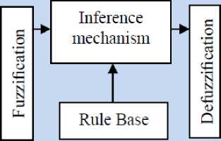
Fig. 1: Fuzzy Controller Part
III. Methodology
Based on the dynamic formulation of IC engine, (3), and the industrial PD law (5) in this paper we discuss about regulation problem, the desired position is constant, i.e., qd =0 . In most IC engine control, desired joint positions are generated by the trajectory planning. The objective of robot control is to design the input torque in (1) such that the tracking error e = FRd - FRa (40)
When the dynamic parameters of robot formulation known, the PD control formulation (11) shoud include a compensator as
PFI=-kpe - kde+(G+F) (41)
Where G is gravity and F is appositive definite diagonal matrix friction term (coulomb friction).
If we use a Lyapunov function candidate as
Vpd
= ^P17 Id{(F̈? d+ Kpe
The fuzzy inference engine offers a mechanism for transferring the rule base in fuzzy set which it is divided into two most important methods, namely, Mamdani method and Sugeno method. Mamdani method is one of the common fuzzy inference systems and he designed one of the first fuzzy managements to control of system engine. Mamdani’s fuzzy inference system is divided into four major steps: fuzzification, rule evaluation, aggregation of the rule outputs and defuzzification. Michio Sugeno use a singleton as a membership function of the rule consequent part. The following definition shows the Mamdani and Sugeno fuzzy rule base [22-33]
+ Kp e, T I
M ̇ air11
Mair21
+ Kpe + Kp e
̇
Mair12+. p1 7 Id{(F ̈ 4
Mair22
d
V Pdi =
1P17 Id{(F ̈ I d+ Kpe + ̇̇
KP e'T.*Ṁ Ṁ +.pF - Id{( F̈1 d+ air21 air22
Kpe + KP e + P ^i7 Id{(F̈^ d+ Kpe +
̇
Kp e. T *Mair11
P Mair2i
Mair12
Mair22
+P17 Id{(F̈? d + ̇ Kpe +I
if x is A and у is В then zis C ' mamdani ' if x is A and у is В then zis f(x,У) ' sugeno '
When x and у have crisp values fuzzification calculates the membership degrees for antecedent part. Rule evaluation focuses on fuzzy operation ( AND/OR ) in the antecedent of the fuzzy rules. The aggregation is used to calculate the output fuzzy set and several methodologies can be used in fuzzy logic controller aggregation, namely, Max-Min aggregation, Sum-Min aggregation, Max-bounded product, Max-drastic product, Max-bounded sum, Max-algebraic sum and Min-max. Defuzzification is the last step in the fuzzy inference system which it is used to transform fuzzy set
It is easy to known ḞR =0 and e=0 are only initial conditions in D = {[q, e ]: V" = 0} , for which [ ḞR,e] ∈ Ω for al l t≤0 . By the LaSalle’s invariance principle, e→0 and e ̇→0 . When G and F in (11) are unknown, a fuzzy logic can be used to approximate them as
f(x)= ∑
1=1
Where
в1£1 (x)= вт£(x)
9=(в 1 ,…,вм )т,ℰ(x)=
(ℰ 1 (x),…,ℰ м (x)) т , ond. ℰ1(x)=
^>1 (xi)
:∏1=1 1—z M=i(∏ P=1^a[ (x,)).
в 1 ,…,в м are
adjustable parameters in (44). Рл^ ( %1 ),…, Ра™ ( хк ) are given membership functions whose parameters will not change over time.
F2 ( FR , Б ̈ )= ⊖ 2? Е ( FR , Б ̈)
= [ 92Те ( FR , F ̈ ) ,…, 9т Е ( FR , F ̈) ] (52)
The second type of fuzzy systems is given by
∑ [∏ ь ехр(-( - ))]
∑ м
∑
F3 ( FR , Б ̈ )= ⊖ 3? Е ( FR , Б ̈)
= [ gfs ( FR , F ̇R) ,…, 9^Те ( FR , Б ̈ ) ] (53)
∏ "=1 ехр
(-( " - ) )]
The control security input is given by
Where в1 , a- and 5- are all adjustable parameters. From the universal approximation theorem, we know that we can find a fuzzy system to estimate any continuous function. For the first type of fuzzy systems, we can only adjust 61 in (45). We define f ^( X | 6 ) as the approximator of the real function f ( X ) .
f ^( X | 9 )= 0Т£ ( X ) (46)
PFI = *Ṁ airn
Ṁ air2i
Mairi2
Ṁ а1г22
+ F ̈ +
We define 6 ∗ as the values for the minimum error:
9 ∗ =argmin[sup| f ^( х | 9 )- д ( X )|] (47)
6 ∈ Lx ∈ и -I
Where fl is a constraint set for в . For specific X , supx ∈ и |/^( X | 9 ∗ )-/( X )| is the minimum approximation error we can get.
We used the first type of fuzzy systems (44) to estimate the nonlinear system (12) the fuzzy formulation can be write as below;
/( X | 9 )= 9те ( х )
∑ ^i^1 [ Ра1 ( х )] =∑ ”=i [ Ра1 ( х )]
Where в1 ,…, дп are adjusted by an adaptation law. The adaptation law is designed to minimize the parameter errors of 6 - 6 ∗ . The SISO fuzzy system is define as
/( X )= ⊖ т Е ( X ) (49)
Where
Г Д1 Д2 дМ 1 "1 , "1 ,…,(71
⊖ т = ( 51,…, ) т = ⎢ 83 , el ,…,63 ⎥
⎣ …
, ,…,
е ( х )=(Е1 ( X ),…, гм ( X )) т , Е1( X )=∏ ^^А\ ( Xi )/ ∑ ^1(∏ ^^а\ ( Xi )) , and РА1. ( Xi ) is defined in (48). To reduce the number of fuzzy rules, we divide the fuzzy system in to three parts:
F1 ( q , ̇)= ⊖ 1Т £ ( FR , F ̇R)
= [ 91тг ( FR , F ̇R) ,…,0m Е ( FR , F ̇R) ] (51)
[P Z1][FṘ α ̇1]+[
LImotor2-l LJ
N11 N12
N21 N22
]×[F α Ṙ̇] +
[M a']+ F1 ( FR , F ̇R)+ F2 ( FR , F ̈ )+
F3 ( FR , Б ̈ )- Kpe - Kvt ̇
^
Where * airn Ṁ air12 + , [P niotori ] [FṘ α̇ , ]+
Ṁ air2i Ṁ air22 ,PИО1ОГ2-1
[N11 N 12]×[FṘ̇] +[MMai] are the estimations of
N N α̇ M
Ṁ airn Ṁ airi2 ]
Ṁ air2i Ṁ air22 +.
If the dynamic formulation of IC engine defined by
PFI =*Ṁairn
Ṁ air2i
Ṁ airi2
Ṁ air22
+ Б VR
+[P ™,„Г1 ] [FṘ α ̇ I ]
LriTiotor2-I
+[N11 N12] ×[FṘ ]2
+[N21 N22]×[ α ̇ ]
+
[Mai
[M ]
The controller formulation is defined by
PFI
=*Ṁ
Ṁ
̂̇ airn M
̇ air2i M
+ Б ̈
̂
+[P ™,„Г1 ] [FṘ α̇ I]+[ Lr]1101012-1 *-
̂
N11 N12
N21 N22
] ×[FṘ ]2
α̇ 1J
F ̇
̂M
+[M ]- p ̈ ?Id {( F ̈? d + Kpe + Kv ̇
According to (58) and (59)
*Ṁ airn Ṁ air2i
Ṁ airi2
Ṁ air22
+ р ̈ +[Pmotor^ ] [FṘ α ̇I]
Pmotor2 -I
∑1=1 θ
+
[ >
N11
N21
*Ṁ Ṁ
NN 22]×[F α Ṙ̇]2+[MM г ] ------
KpC + Kp ̇+
∏ ‘-exp ( ( δ- α 5 ))+
∑ n, *∏ ^exp( ( δ j α 1 ))+
+
alt'll
air2i
Mairi2
Ṁ air22
+ F ̈
̂
+
[P ] [FṘ α ̇ I]+[
Umoto^J L
̂
N11 N12
N21 N22.
]×[F α Ṙ̇]2
+
M
[M ]- p ̈ 7Id {( F ̈ ^ d + Крв + Kp ̇
This method has two main management’s
coefficients, Kp and Kv . To tune and optimize parameters mathematical formulation is used
these
U = + ^computed + UpD
U=Ufuzzy+U =
[
Ṁ
Ṁ air2i
N11 N12
N21 N22
Ṁ airi2
Ṁ air22
+ ([PP uotor2][FṘ α̇1 ]+
]×[F α Ṙ̇] 2 )+
Kp^t + Kvae ̇1
The most important different between PD+CFC and PD+CFC+FL is the uncertainty. In PD+CFC the uncertainty is d = G + F + f . The computed fuel ratio gain must be bigger than its upper bound. It is not an easy job because this term includes tracking errors ег and ̇ 2_ . While in PD+CFC+FL, the uncertainty η is the fuzzy approximation error for G + F + f.
G + F + =
∑ м1в1 *∏ ^exp ( ( x_H ))+ ∑ ^=1 *∏ V^exp ( (^ ) )+
It is usually is smaller than G + F + f ; and the upper bound of it is easy to be estimated. Figure 2 shows the control unit methodology to tune the output performance.
Ṁ airn Ṁ airi2̈̈
Ṁ air2i Ṁ air22 ++ ̈ {( ̈ +
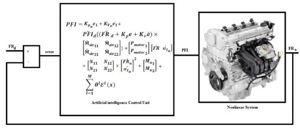
Fig. 2: Design AI Control Unit to tune the fuel ratio
IV. Results and Discussion
In this section, we use a benchmark model, IC engine, to evaluate our control algorithms [22]. We compare the following methodologies: classical PD methodology, PD fuzzy methodology and serial fuzzy computed fuel ratio PD methodology which is proposed in this paper. The simulation was implemented in MATLAB/SIMULINK environment.
Close loop response of IC engine fuel ratio: Figure 3 illustrates the tracking performance in three types of methodologies; linear PD method, linear PD method based on fuzzy logic estimator and nonlinear estimator based on fuzzy logic and computed fuel ratio method.
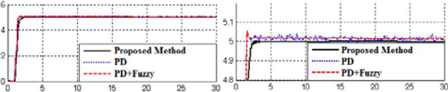
Fig. 3: Linear PD, PD+FLC and Proposed method fuel ratio following without disturbance
Based on Figure 3; pure PD management has oscillation in first and three links, because IC engine is a highly nonlinear management and control of this system by linear method is very difficult. Based on above graph, however PD+FUZZY controller is a nonlinear methodology but it has difficulty to control this plant because it is a model base controller.
Close loop response of fuel ratio following in presence of load disturbance: Figure 4 demonstrates the power disturbance elimination in three types of controller in presence of disturbance for IC engine. The disturbance rejection is used to test the robustness comparisons of these three methodologies.
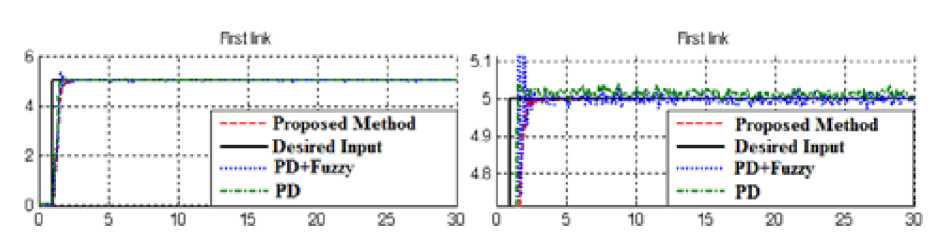
Fig. 4: Linear PD, PD+FLC and Proposed method fuel ratio following with disturbance
Based on Figure 3; by comparison with the PD and PD+FLC, proposed serial compensator PD+Fuzzy+CFM is more stable and robust and our method doesn’t have any oscillation.
-
V. Conclusion
The main contributions of the paper are twofold. The first advantage of proposed method is increase the stability and robustness and the second one is artificial intelligence based dynamic method based on parallel method. The structure of fuzzy PD control with computed fuel ratio compensation is new. We propose parallel structure and robust nonlinear compensator. The key technique is dead-zone, such that fuzzy control and computed fuel ratio control can be switched automatically. The stability analysis of fuzzy computed fuel ratio PD manages is also new. Stability analysis of fuzzy PD algorithm with first-order or second-order computed fuel ratio is not published in the literature. The benefits of the proposed method; the stabilityA effects of fuzzy computed fuel ratio PD methodology, the slow convergence of the fuzzy PD and the chattering problem of computed fuel ratio PD method are avoided effectively.
Acknowledgment
The authors would like to thank the anonymous reviewers for their careful reading of this paper and for their helpful comments. This work was supported by the SSP Research and Development Corporation Program of Iran under grant no. 2012-Persian Gulf-3C.
References Robust Fuzzy PD Method with Parallel Computed Fuel Ratio Estimation Applied to Automotive Engine
- Heywood, J., “Internal Combustion Engine Fundamentals”, McGraw-Hill, New York, 1988.
- J. G. Rivard, "Closed-loop Electronic Fuel Injection Control of the IC Engine," in Society of Automotive Engineers, 1973.
- J. F. Cassidy, et al, "On the Design of Electronic Automotive Engine Controls using linear Quadratic Control Theory," IEEE Trans on Control Systems, vol. AC-25, October 1980.
- W. E. Powers, "Applications of Optimal Control and Kalman Filtering to Automotive Systems," International Journal of Vehicle Design, vol. Applications of Control Theory in the Automotive Industry, 1983.
- N. F. Benninger, et al, "Requirements and Perfomance of Engine Management Systems under Transient Conditions," in Society of Automotive Engineers, 1991.
- N. F. Benninger, et al, "Requirements and Perfomance of Engine Management Systems under Transient Conditions," in Society of Automotive Engineers, 1991.
- C. H. Onder, et al, "Model-Based Multivariable Speed and Air-to-Fuel Ratio Control of an SI Engine," in Society of Automotive Engineers, 1993.
- S. B. Cho, et al, "An Observer-based Controller Design Method for Automotive Fuel-Injection Systems," in American Controls Conference, 1993, pp. 2567-2571.
- T. Kume, et al, "Combustion Technologies for Direct Injection SI Engine," in Society of Automotive Engineers, 1996.
- V. Utkin, "Variable structure systems with sliding modes," Automatic Control, IEEE Transactions on, No. 2, vol. 22, pp. 212-222, 2002.
- R. A. DeCarlo, S. H. Zak and G. P. Matthews, "Variable structure control of nonlinear multivariable systems: a tutorial," Proceedings of the IEEE, No. 3, vol. 76, pp. 212-232, 2002.
- K. D. Young, V. Utkin and U. Ozguner, "A control engineer's guide to sliding mode control," IEEE conference proceeding, 2002, pp. 1-14.
- O. Kaynak, "Guest editorial special section on computationally intelligent methodologies and sliding-mode control," IEEE Transactions on Industrial Electronics, No. 1, vol. 48, pp. 2-3, 2001.
- P. Kachroo and M. Tomizuka, "Chattering reduction and error convergence in the sliding-mode control of a class of nonlinear systems," Automatic Control, IEEE Transactions on, No. 7, vol. 41, pp. 1063-1068, 2002.
- J. Moura and N. Olgac, "A comparative study on simulations vs. experiments of SMCPE," IEEE conference proceeding, 2002, pp. 996-1000.
- Farzin Piltan , N. Sulaiman, Zahra Tajpaykar, Payman Ferdosali, Mehdi Rashidi, “Design Artificial Nonlinear Robust Controller Based on CTLC and FSMC with Tunable Gain,” International Journal of Robotic and Automation, 2 (3): 205-220, 2011.
- Farzin Piltan, A. R. Salehi and Nasri B Sulaiman.,” Design artificial robust control of second order system based on adaptive fuzzy gain scheduling,” world applied science journal (WASJ), 13 (5): 1085-1092, 2011.
- Farzin Piltan, Nasri Sulaiman, M. H. Marhaban and R. Ramli, “Design On-Line Tunable Gain Artificial Nonlinear Controller,” Journal of Advances In Computer Research, 2 (4): 75-83, 2011.
- Farzin Piltan, N. Sulaiman, Payman Ferdosali, Iraj Assadi Talooki, “ Design Model Free Fuzzy Sliding Mode Control: Applied to Internal Combustion Engine,” International Journal of Engineering, 5 (4):302-312, 2011.
- Farzin Piltan, N. Sulaiman, Iraj Asadi Talooki, Payman Ferdosali, “Control of IC Engine: Design a Novel MIMO Fuzzy Backstepping Adaptive Based Fuzzy Estimator Variable Structure Control ,” International Journal of Robotics and Automation, 2 (5):360-380, 2011.
- Farzin Piltan, N. Sulaiman, Payman Ferdosali, Mehdi Rashidi, Zahra Tajpeikar, “Adaptive MIMO Fuzzy Compensate Fuzzy Sliding Mode Algorithm: Applied to Second Order Nonlinear System,” International Journal of Engineering, 5 (5): 380-398, 2011.
- Farzin Piltan, N. Sulaiman, Hajar Nasiri, Sadeq Allahdadi, Mohammad A. Bairami, “Novel Robot Manipulator Adaptive Artificial Control: Design a Novel SISO Adaptive Fuzzy Sliding Algorithm Inverse Dynamic Like Method,” International Journal of Engineering, 5 (5): 399-418, 2011.
- Farzin Piltan, N. Sulaiman, Sadeq Allahdadi, Mohammadali Dialame, Abbas Zare, “Position Control of Robot Manipulator: Design a Novel SISO Adaptive Sliding Mode Fuzzy PD Fuzzy Sliding Mode Control,” International Journal of Artificial intelligence and Expert System, 2 (5):208-228, 2011.
- Farzin Piltan, SH. Tayebi HAGHIGHI, N. Sulaiman, Iman Nazari, Sobhan Siamak, “Artificial Control of PUMA Robot Manipulator: A-Review of Fuzzy Inference Engine And Application to Classical Controller ,” International Journal of Robotics and Automation, 2 (5):401-425, 2011.
- Farzin Piltan, Amin Jalali, N. Sulaiman, Atefeh Gavahian, Sobhan Siamak, “Novel Artificial Control of Nonlinear Uncertain System: Design a Novel Modified PSO SISO Lyapunov Based Fuzzy Sliding Mode Algorithm ,” International Journal of Robotics and Automation, 2 (5): 298-316, 2011.
- Farzin Piltan, N. Sulaiman, S.Soltani, M. H. Marhaban & R. Ramli, “An Adaptive sliding surface slope adjustment in PD Sliding Mode Fuzzy Control for Robot Manipulator,” International Journal of Control and Automation , 4 (3): 65-76, 2011.
- Farzin Piltan, N. Sulaiman, Amin Jalali, Sobhan Siamak, and Iman Nazari, “Control of Robot Manipulator: Design a Novel Tuning MIMO Fuzzy Backstepping Adaptive Based Fuzzy Estimator Variable Structure Control ,” International Journal of Control and Automation, 4 (4):91-110, 2011.
- Farzin Piltan, N. Sulaiman and I.AsadiTalooki, “Evolutionary Design on-line Sliding Fuzzy Gain Scheduling Sliding Mode Algorithm: Applied to Internal Combustion Engine,” International Journal of Engineering Science and Technology, 3 (10):7301-7308, 2011.
- Farzin Piltan, Nasri B Sulaiman, Iraj Asadi Talooki and Payman Ferdosali.,” Designing On-Line Tunable Gain Fuzzy Sliding Mode Controller Using Sliding Mode Fuzzy Algorithm: Applied to Internal Combustion Engine,” world applied science journal (WASJ), 15 (3): 422-428, 2011.
- Farzin Piltan, H. Rezaie, B. Boroomand, Arman Jahed,” Design robust back stepping online tuning feedback linearization control applied to IC engine,” International Journal of Advance Science and Technology, 42: 183-204, 2012.
- Piltan, F., et al. "Design sliding mode controller for robot manipulator with artificial tunable gain". Canaidian Journal of pure and applied science, 5 (2), 1573-1579, 2011.
- Farzin Piltan, Bamdad Boroomand, Arman Jahed, Hossain Rezaie. "Performance-Based Adaptive Gradient Descent Optimal Coefficient Fuzzy Sliding Mode Methodology ". International Journal of Intelligent Systems and Applications, 4 (11), 40-52, 2012.
- Farzin Piltan, Reza Bayat, Saleh Mehrara, Javad Meigolinedjad. "GDO Artificial Intelligence-Based Switching PID Baseline Feedback Linearization Method: Controlled PUMA Workspace". International Journal of Information Engineering and Electronic Business, 4 (5), 17-26, 2012.
