
Scaling up the application process of “Ni–SiC” metal-matrix composite coating
Журнал: Nanotechnologies in Construction: A Scientific Internet-Journal @nanobuild-en
Рубрика: Construction materials science
Статья в выпуске: 5 Vol.18, 2026 года.
Бесплатный доступ
Introduction. Today, metal-matrix composite coatings are widely in demand due to the possibility of combining the properties of both the metal base and their reinforcing particles. The simplest and most technologically advanced method of coating is electrodeposition. One of the key parameters that determines the quality of the coating formed and the electrodeposition rate is current density. The literature presents opposing views on how current density affects the quality of composite coatings. The primary criterion is the volume fraction of reinforcing particles. The use of nanoparticles (less than 100 nm in size) as a hardener makes it possible to significantly increase the hardness and wear resistance of the matrix due to dispersion hardening, however, they have a high tendency to agglomeration and require more careful control of electrodeposition modes. It is important during electrodeposition to form a coating with a uniform distribution of particles in the metal matrix over the entire working area of the workpiece to ensure stability of mechanical and functional properties, which will subsequently determine the durability of the parts. From this point of view, it is of interest to scale the electrodeposition process and switch to model samples, the long size of which imitates the maximum height of a real axisymmetric part, for example, a cylinder, which will allow reproducing coating conditions close to production ones. The aim of the research is to study the homogeneity of the structure and properties of the Ni–SiC coating containing a fraction of particles larger than 2 μm and formed on long workpieces (with an area of 0.2 dm2) in the process of electrodeposition depending on the current density. Methods and materials. Cast aluminum alloy AK7 was used as the substrate material for forming the Ni–SiC composite coating. The dimensions of the substrate samples were 70×20×4 mm. Electrodeposition mode: current density of 0.5 A/dm2, 10 A/dm2, 20 A/dm2; duration 60 minutes; temperature 60 °C. The microstructure of the coatings was examined using a JSM-6490 LV scanning electron microscope at a magnification of ×500. Microhardness was estimated using a TBM Tochline microhardness tester at a load of 50 g. Wear resistance tests were performed on a Nanovea tribometer using the ball-on-disk method. Results and discussion. The technology of electrodeposition of the matrix composite coating “Ni–SiC” on long flat samples (0.2 dm2) of aluminum alloy AK7 was developed and the optimal process parameters were selected. The possibility of forming a homogeneous coating based on a nickel matrix containing large SiC particles on flat long samples (0.2 dm2) of aluminum alloy AK7, simulating a sector of an axisymmetric part, was demonstrated. Conclusion. The metal-matrix composite coating “Ni–SiC”, formed on flat long samples (with an area of 0.2 dm2) of aluminum alloy AK7 as a result of electrodeposition, is characterized by uniformity of thickness, volume fraction of silicon carbide particles and microhardness in three control zones for each current density. The higher the current density during electrodeposition, the higher the thickness of the formed Ni–SiC metal matrix composite coating, the volume fraction of reinforcing particles and the microhardness.
Короткий адрес: https://sciup.org/142249014
IDS: 142249014 | DOI: 10.15828/2075-8545-2026-18-5-580-590
Текст научной статьи Scaling up the application process of “Ni–SiC” metal-matrix composite coating
Original article
Киселева С.К., Ахмеров Л.Д., Хуснутдинова А.З., Кандаров И.В. Масштабирование процесса нанесения металломатричного композиционного покрытия «Ni–SiC». Нанотехнологии в строительстве. 2026;18(5):580–590. – EDN: SJSTWL.
Today, metal-matrix composite coatings (MMCCs) are widely in demand due to the possibility of combining the properties of both the metal base and their reinforcing particles. The introduction of reinforcing particles improves the mechanical properties of the coatings, their corrosion resistance, and expands their applications [1, 2].
The development of various methods for introducing particles into a metal matrix is gaining significant importance due to the potential for synthesizing a wide range of materials with unique functional properties. The simplest and most technologically advanced coating method is electrodeposition [3], which involves the reduction of metal ions from an electrolyte based on salt solutions under the influence of an electric current. The workpiece acts as a cathode and is connected to the negative pole of the power source, while the anode, typically an electrode in an electrolyte solution of the same metal, is connected to the positive pole. The physicochemical principles of electrodeposition are well known in electroplating.
Of particular interest among the MMCCs obtained by electrodeposition are nickel composite coatings. The introduction of solid particles of SiC [4], Al2O3 [5], ZrO2 [4], WC [6] and TiO2 [7] leads to a significant improvement in the mechanical properties of the coatings, such as strength, hardness and wear resistance, and determines their potential application.
The most extensive research has been conducted on nickel-matrix composites containing embedded silicon carbide (SiC) particles. For components operating under conditions of intense friction and mechanical stress, and used in the automotive, aerospace, and manufacturing industries, the Ni–SiC system is indispensable as a protective coating [8, 9]. Previously, galvanic chromium plating was used to harden the surface of components such as aluminum cylinders and piston rings. However, switching to a Ni–SiC coating reduces environmental pollution and avoids negative impacts on human health [10].
As is known, the advantage of the Ni–SiC coating electrodeposition process is the ability to control the structure and properties by changing such process parameters as electrolyte composition, temperature, stirring speed and particle content [1, 9], as well as the relative position of the cathode and anode during electrodeposition [11, 12]. The latter parameter becomes most significant in the development of a technology for electrodeposition of a coating containing a large fraction of particles larger than 2 µm. The authors [12] note that the horizontal position of the treated surface allows for the stable production of a Ni–SiC composite coating characterized by good adhesion. It is worth noting that in these studies the coating was formed on flat samples with an area of 0.1 dm2.
Another fundamental parameter determining the quality of the formed coating and the electrodeposition rate is the current density ρ. It is noted [ ] that there is an optimal range of ρ, in which a coating with the maximum particle content is formed. For example, for nanosized SiC particles this range is from 40 to 60 mA/cm2.
During electrodeposition, it’s crucial to form a coating with a uniform particle distribution in the metal matrix across the entire working surface of the workpiece to ensure stable mechanical and functional properties, which will ultimately determine the longevity of the components. From this perspective, it’s of interest to scale up the electrodeposition process and switch to model samples whose lengths mimic the maximum height of a real axisymmetric component, such as a cylinder, allowing for the reproduction of coating application conditions similar to those in production.
Thus, the aim of this work is to study the homogeneity of the structure and properties of the Ni–SiC coating containing a fraction of particles larger than 2 µm and formed on long workpieces (0.2 cm2 area) in the process of electrodeposition depending on the current density.
MATERIALS AND METHODS
Raw material
Cast aluminum alloy AK7 (GOST 30620-98) was used as the substrate material for the Ni–SiC composite coating. Its microhardness was 58HV. The size of the flat samples was chosen to match the linear dimension of a sector of an axisymmetric cylindrical part and was 70 mm long, 20 mm wide, and 4 mm thick.
The chemical element content of the substrate material was assessed using an INCA-Energy X-ray microanalyzer and an Inca X-Act energy-dispersive spectrometer, both of which are equipped with a JSM-6490 LV scanning electron microscope (SEM). Analysis of five spectra taken from the sample surface revealed the following average component content (wt %): Al – 81.0; Si – 18.0; Mg – 0.1.
Surface preparation of samples before coating
Surface preparation was performed to improve adhesion of the coating to the substrate material. It included several steps:
-
– degreasing in an ultrasonic bath with acetone for 2 minutes;
-
– rinsing in warm distilled water;
-
– etching in a solution of hydrofluoric (HF) and nitric acids (HNO3) for 3 minutes;
-
– rinsing twice in distilled water at room temperature.
After rinsing, the flat samples were immediately mounted in the setup to prevent the substrate surface
Nanotechnologies in construction
Нанотехнологии в строительстве
2026; 18 (5): 580–590
Nanob
CONSTRUCTION MATERIALS SCIENCE
from drying out and the re-formation of the natural oxide film due to interaction with atmospheric oxygen.
Electrodeposition
For coating application, a Watts sulfamate electrolyte was used, the composition of which is presented in Table 1 [14].
The electrolyte for Ni–SiC deposition was prepared as follows. Boric acid, nickel chloride, nickel sulfate, and sodium lauryl sulfate were dissolved sequentially in a glass container filled with distilled water to 3/4 of the required
Table 1. Electrolyte composition and electrodeposition parameters
|
Components |
Concentration, g/l |
|
Single nickel salt (Ni2SO4·7H2O) |
300l |
|
Nickel chloride (NiCl2) |
30 |
|
Boric acid (H3BO3) |
30 |
|
Sodium lauryl sulfate (C12H25SO4Na) |
1.5 |
|
Silicon carbide (SiC) |
150 |
|
Electrodeposition parameters |
Value |
|
Temperature (°C) |
60±1 |
|
Ph |
3.5…4.0 |
|
Processing duration τ, min |
60 |
|
Stirring speed n, rpm |
from 1 to 300 |
|
Current density j, A/dm2 |
0.5; 10,0; 20.0 |
Preparing samples for research
volume at a temperature of up to 70 °C. The electrolyte was then topped up to the required volume and silicon carbide was added.
An NPA2 electrolytic nickel rod (GOST 492-2006) was used as the anode.
The apparatus for electrodepositing a composite coating is shown in Fig. 1 and consists of a cylindrical bath 1 and two funnel-shaped end caps 2 and 3, which cover the ends of the bath with a cylindrical nickel anode 4 placed therein. A flat sample is attached to the inner wall of the bath. The bath with the caps is mounted in a movable frame 6 capable of rotation around an axis of symmetry to transmit centrifugal forces to the electrolyte (7 in Fig. 1) with SiC particles (8 in Fig. 1). A fixed frame 9 allows the position of the bath 1 to be changed relative to the vector of the earth’s gravitational field. Sample 5 made of aluminum alloy, which serves as the cathode, and cylindrical nickel anode 4 are connected to a DC source.
The electrodeposition mode was selected based on the experimental results obtained earlier [12, 13]: the electrolyte temperature was 60 °C, the stirring speed varied depending on the position of the bath relative to the vector of the gravitational field of the earth’s attraction (from 1 to 300 rpm), and the treatment duration was 60 minutes (Table 1).
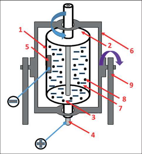
Fig. 1. Device for electrodeposition of Ni–SiC coating
Electrodeposition of the composite coating was carried out on three samples. Electrodeposition modes differed in current density according to Table 1. To carry out metallographic studies, microsections were prepared in the following sequence: cutting blanks for transverse microsections on an electric spark machine; mechanical grinding using abrasives with a grain size up to P2000 (10 microns) and subsequent polishing using polishing suspensions on grinding and polishing equipment.
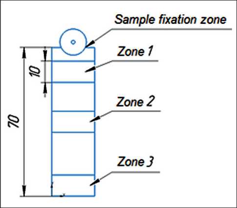
Fig. 2. Scheme of cutting samples for research
Nanotechnologies in construction
Нанотехнологии в строительстве
2026; 18 (5): 580–590
Nanob
CONSTRUCTION MATERIALS SCIENCE
Microstructural analysis technique
JSM-6490 LV scanning electron microscope (SEM) at ×500 magnification was used to determine the coating thickness and quantify the silicon carbide content. The volume fraction of silicon carbide in the coating was determined using the grid overlay method [1].
The chemical element content of the coating was assessed using an INCA-Energy X-ray microanalyzer and an Inca X-Act energy-dispersive spectrometer, both of which are equipped with JSM-6490 LV scanning electron microscope (SEM).
Test methods for wear resistance and microhardness
Wear resistance tests in zone 2 were carried out on a Nanovea tribometer using the ball-on-disk method in the following modes: rotation speed – 286 rpm; friction circle radius – 5 mm; linear velocity – 0.063 m/s; force – 2 N; friction type – dry; maximum track length – 1000 m; counterbody – steel ball with a diameter of 6.3 mm. Three parameters were selected as wear characteristics: the magnitude of mass wear of the sample (W), the magnitude of mass wear of the counterbody (Wb) and the wear track width ( b ).
The value of mass wear of the sample was calculated using the formula:
W = ( m 0– mk / m 0)×100%, (1)
where m 0 – sample weight before testing, kg;
mk – sample weight after testing, kg.
The magnitude of mass wear of the counterbody was determined by the formula:
W ш = ( m 0ш– mk ш/ m 0ш)×100%, (2)
where m 0 b – mass of the ball before testing, kg;
mk b – mass of the ball after testing, kg.
The microhardness (HV) in the cross section was assessed using a TBM Tochline microhardness tester with a load of 50 g and an indentation time of 10 s.
RESULTS
Coating microstructure
Electrodeposition resulted in coatings on samples of AK18 aluminum alloy. Visual inspection of the sample surfaces revealed no delamination of the coating from the substrate or any defects such as discontinuities.
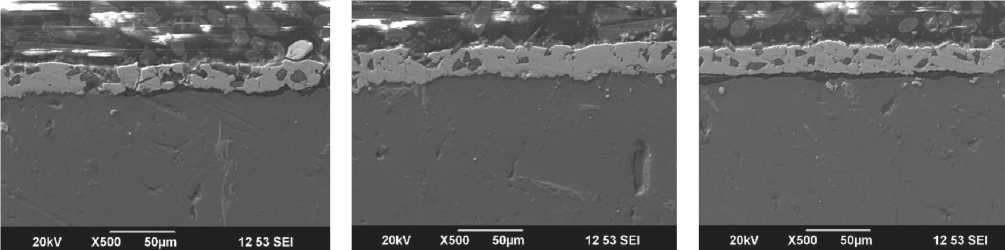
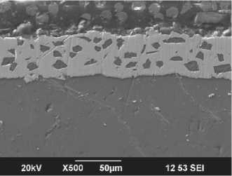
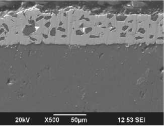
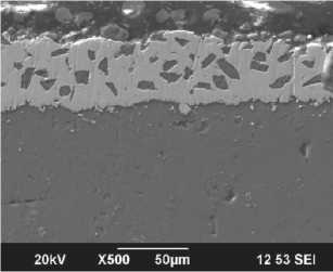
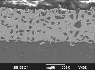
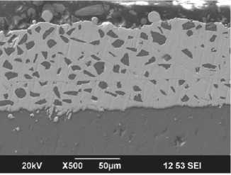
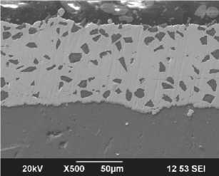
The microstructure of cross-sections of the electrodeposited samples is shown in Figure 3. The coatings formed intact without cracks, and good adhesion to the substrate is evident. No defects, such as pores, were observed along the transition zone from the base material to the coating. The coating consists of a nickel matrix with embedded silicon carbide particles, as clearly demonstrated by the elemental composition of the coating (Fig. 4).
A comparative analysis of the coating morphology (Fig. 3) and thickness assessment in different zones (Fig. 5a) indicate uniform formation across the entire surface of the samples. At low current densities (j = 0.5 A/dm²), the coating thickness varies from 17 to 25 µm depending on the zone. As the current density increases to 10 and then to 20 A/dm², the coating thickness increases by almost two and four times compared to j = 0.5 A/dm². Thickness uniformity is maintained across different zones and is within the error margin.
The volume fraction of silicon carbide particles increases with increasing current density (Fig. 5b) from 10% at 0.5 A/dm2 to 15% (j = 10.0 A/dm2) and 16% (j = 20.0 A/dm2). Despite the fact that the coating thickness increases significantly with increasing current density, a similar multiple increase in the volume fraction of silicon carbide particles is not observed.
Coating microhardness
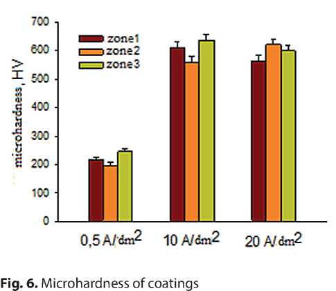
As shown in Figure 6, the coating microhardness depends on current density. At low current density (0.5 A/dm²), microhardness reaches no more than 250 HV. As j increases to 10.0 A/dm², microhardness increases almost threefold (637 HV for zone 2). A further increase in current density to 20 A/dm² does not result in an increase in HV.
For j = 0.5 A/dm2, the coating microhardness in zones 1, 2, and 3 (according to the cutting diagram in Fig. 2) varies within the error limits. Similar uniformity of coating microhardness in different zones of the samples is observed for the electrodeposition mode at current densities of 10 and 20 A/dm2.
Coating wear resistance
Tribometer testing is used to evaluate the adhesion quality of coatings to the substrate surface. No delamination or failure of coatings formed at different current densities was observed in tribological tests. The wear tracks [16] formed during the tests are shown in Figure 7. Table 2 shows the specimen wear (W), the counterface wear (Wb), and the wear track width (b). These characteristics, as is well known, can be used to assess the intensity of surface damage.
The obtained data indicate increased wear resistance compared to the substrate material. The sample obtained at a current density of 0.5 A/dm² exhibited the highest wear resistance, corresponding to the lowest mass loss. As the current density increased to 10 A/dm² and 20 A/dm²,
Nanotechnologies in construction
Нанотехнологии в строительстве
2026; 18 (5): 580–590
Nanob
CONSTRUCTION MATERIALS SCIENCE
а, zone 1 b, zone 2 с, zone 3
d, zone 1
e, zone 2
f, zone 3
g, zone 1
Fig. 3. Microstructure of cross-sections of coated samples, SEM: a, b, c – 0.5 A/dm2; d, e, f – 10.0 A/dm2; g, h, k – 20.0 A/dm2
h, zone 2
k, zone 3
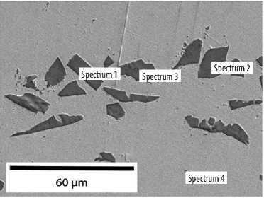
Fig. 4. Elemental composition of the coating
|
№ spectrum C |
Si |
Ni |
|
|
spectrum 1 |
40,7 |
58,2 |
1,0 |
|
spectrum 2 |
41,6 |
57,1 |
1,2 |
|
spectrum 3 |
39,8 |
57,7 |
13 |
|
spectrum 4 |
- |
- |
100 |
Nanotechnologies in construction
Нанотехнологии в строительстве
2026; 18 (5): 580–590
Nanob
CONSTRUCTION MATERIALS SCIENCE
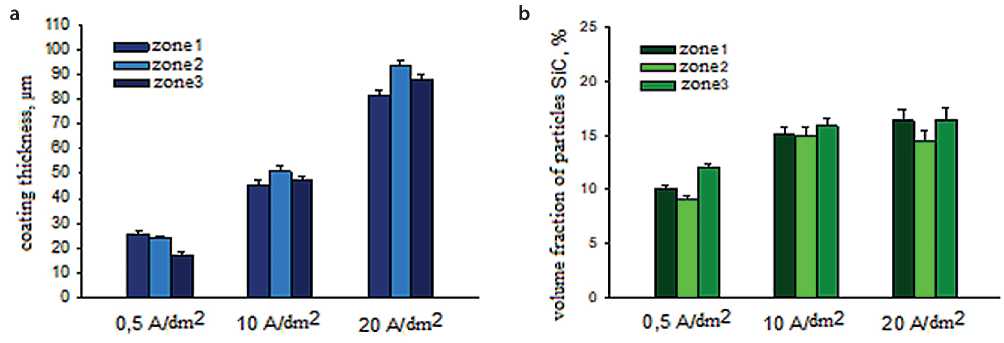
Fig. 5. Comparative analysis of coatings obtained at different current densities: coating thickness (a); volume fraction of SiC particles (b)
mass loss increased, but remained 2.5–3.5 times higher than that of AK7. The samples obtained at a current density of 0.5 A/dm² and 20 A/dm² exhibited the smallest wear track widths, indicating good adhesion strength.
Thus, the coatings formed on flat samples of AK7 aluminum alloy are characterized by homogeneity over the entire area, while their structure and properties depend on the current density.
DISCUSSION
Electrodeposition is known to be one of the most common methods for producing composite coatings based on a metal matrix on the surface of components [17]. A basic electrodeposition setup consists of two conductive electrodes immersed in an electrolyte bath. One working electrode is connected to the negative pole and serves as the cathode, while the other is connected to the positive pole. When an external electric field is applied, cations move toward the cathode, discharge, and are deposited as a metallic layer [18, 19]. To date, sufficient laboratory experience has been accumulated in forming composite coatings reinforced with particles such as SiC, Al2O3, WC, TiO2, and others. However, the transition from laboratory samples to product processing presents a challenge, primarily related to the need to form coatings exclusively on the working surfaces. Ensuring uniformity of coating formation is also crucial.
As a result of the conducted research, the possibility of obtaining a Ni–SiC composite coating on model samples, the long dimension of which simulates
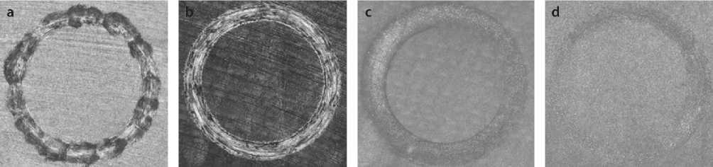
Fig. 7. Wear tracks: AK18 (a); 0.5 A/dm2 (b), 10 A/dm2 (c), 20 A/dm2 (d)
Nanotechnologies in construction
Нанотехнологии в строительстве
CONSTRUCTION MATERIALS SCIENCE
2026; 18 (5): 580–590
Nanob
Table 2. Results of tribological tests
Current density is considered a key factor that directly affects the quality of the composite coating formed on the base metal substrate [20]. The mechanism of inclusion of SiC into the nickel matrix, and, consequently, the rate of incorporation, at low current densities is determined by adsorption, and at high current densities by the transport of second-phase particles [21]. The literature contains conflicting opinions on the effect of current density on the quality of composite coatings. The primary criterion is the volume fraction of reinforcing particles. In most cases, an increase in the particle fraction is observed with increasing current density [3, 20, 22]. However, there are publications whose authors demonstrate the opposite effect – a decrease in the volume fraction with an increase in current density [23]. In [13], it is noted that with increasing current density, an increase in the volume fraction of particles is initially observed, followed by a decrease with further increases in current density. This discrepancy can be explained by the fact that the authors use different methods of mixing the electrolyte, different sizes of reinforcing particles (from nanoscale to micron-scale), and different relative positions of the cathode and anode.
It should be noted that when using nanoscale SiC particles, a more pronounced dependence of the content of the hardener on the current density is observed. Studies show that nanoparticles are characterized by a decrease in switching efficiency at high current densities, which is associated with increased competition between nickel ion discharge processes and electrophoretic particle transfer [24, 25]. In addition, nanoparticles are critically important to prevent their agglomeration in the electrolyte, which can be achieved by using ultrasonic mixing [26]. Unlike micron particles, for which convection is the determining mechanism of delivery to the cathode, nanoparticles are more susceptible to the influence of electrokinetic phenomena and require more careful control of deposition parameters [27].
In the current study, increasing the current density resulted in an increase in both the volume fraction of silicon carbide particles and an increase in the thickness of the formed coating (Fig. 5). Silicon carbide particles are known to have a negative charge. In the electrolyte solu- tion, nickel ions are adsorbed onto the particle surface, and due to the positive charge, they are incorporated into the coating [28, 29, 30]. Electrodeposition processes are known to obey Faraday’s first law [31]. It can be assumed that with increasing current density, a larger mass of nickel is adsorbed on the silicon carbide particles and, with their further deposition on the base metal substrate, a coating of greater thickness is formed.
The performance characteristics of coatings for practical applications are determined by mechanical properties such as microhardness and adhesion. These properties determine the quality of the coating and may vary depending on its structure.
Metal-matrix composites are characterized by higher microhardness values compared to coatings based on pure metal. This is explained by the mechanism of dispersion strengthening of the matrix by inclusions of co-precipitated strengthening particles, which act as barriers to dislocation movement [32, 33, 34]. It is known that the microhardness of metal-matrix composites depends not only on the mechanical characteristics of the matrix nickel phase, particles, and interphase boundaries, but also on the amount of the dispersed phase [3, 7]. The obtained results confirm this trend. When evaluating the microhardness, a greater consistency was revealed with the volume fraction of silicon carbide particles in the coating composition than with its thickness (compare Fig. 5 and Fig. 6).
The wear resistance of Ni–SiC composite coatings depends on the current density through the thickness and volume fraction of embedded solid particles in the coating. As with microhardness, the volume fraction of particles has a more pronounced effect than the coating thickness. The best wear resistance was achieved for a coating containing 10% SiC, obtained at a density of 0.5 A/dm2. The increase in mass loss and the resulting decrease in wear resistance at current densities of 10 and 20 A/dm2 can be associated with the tearing out of particles during friction, which leads to additional wear of the coating surface. In the literature, the term “third-body wear” is used to describe this process [35]. In this case, scratches are observed on the wear tracks of the Ni–SiC composite coating and their absence on the wear tracks of the pure nickel-based coating. With increasing coating thickness, the volume fraction of particles increases, consequently, the percentage of particles torn out of the
Nanotechnologies in construction
Нанотехнологии в строительстве
2026; 18 (5): 580–590
Nanob
CONSTRUCTION MATERIALS SCIENCE
metal matrix increases. For nanocomposite coatings, the wear mechanisms may differ: the uniform distribution of nanoparticles in the matrix contributes to a more stable formation of the protective layer and a reduction in abrasive wear [27, 36].
CONCLUSION
Thus, this study demonstrates the feasibility of scaling up the process of electrodeposition of “Ni–SiC” metalmatrix composite coating on long, flat specimens of AK7 aluminum alloy. The following conclusions can be drawn from this work:
-
1. The metal-matrix composite coating “Ni–SiC”, formed on flat long samples (0.2 cm2 area) of AK7 aluminum alloy as a result of electrodeposition, is characterized by uniformity of thickness, volume fraction of silicon carbide particles and microhardness in three control zones for each current density.
-
2. The higher the current density during electrodeposition, the higher the thickness of the formed Ni–SiC metal-matrix composite coating, the volume fraction of reinforcing particles and the microhardness.
-
3. Mass loss during tribological tests for a sample coated with “Ni–SiC” composite coating is lower than for an uncoated sample.